Lokiel's "Gina" (2004 Titanium SE)

Chat to do with your MX5/Miata/Eunos Garage Ride(s).

Moderators: timk, Stu, zombie, Andrew, The American, Lokiel, -alex, miata, StanTheMan, greenMachine, ManiacLachy, Daffy

User avatar
ManiacLachy
Forum Guru
Posts: 3266
Joined: Mon Jan 13, 2014 2:35 pm
Vehicle: NB SE
Location: Brisbane

Re: Lokiel's "Gina" (2004 Titanium SE)

Postby ManiacLachy » Tue Aug 09, 2022 10:10 am

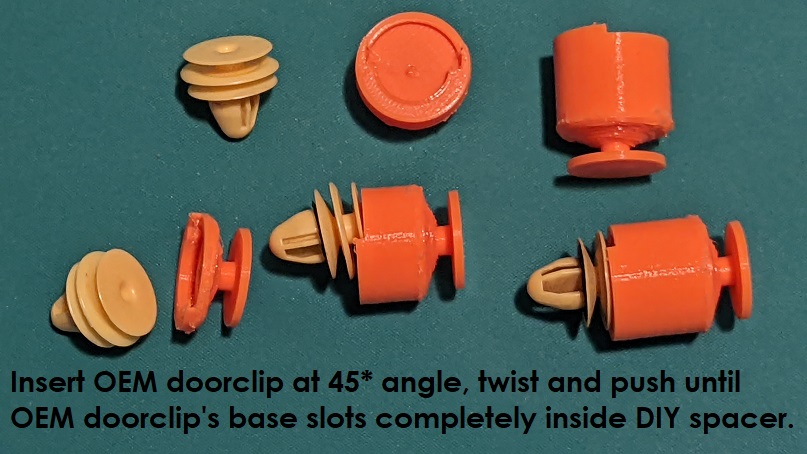
Lokiel wrote:I tweaked my initial doorclip design so that the nylon door clips could "lock into" my doorclip spacers.

That is a brilliant idea! Well done :NETPOINTZ:

Lokiel wrote:I'll publish these on one of the 3D model sites for those that want them (ManiacLachy, I've got your set printed already because you "bagsed" them in one of the above posts).

Thank you! I'll arange a time to come over to pick up and shoot the poop.

Lokiel wrote:... more stuff coming, just need time to complete some of the tasks remaining.

Like the Lokiel gauge completion? :mrgreen:

User avatar
Lokiel
Forum legend
Posts: 4126
Joined: Thu May 28, 2009 2:39 pm
Vehicle: NB SE
Location: Brisbania

Re: Lokiel's "Gina" (2004 Titanium SE)

Postby Lokiel » Tue Aug 09, 2022 11:52 am

bruce wrote:That clip next to the pictured top left clip is near impossible to attach, it slides on (if same as NA).

- I believe you're talking about the un-circled one hole.
I never bothered to even try to use that one since the speaker going through the padded speaker hole holds that section in place firmly - it's how I start the door-card alignment.
Don't worry about dying, worry about not living!
Garage Thread: http://www.mx5cartalk.com/forum/viewtopic.php?f=57&t=76716

User avatar
bruce
Speed Racer
Posts: 7706
Joined: Fri Apr 25, 2003 11:00 am
Vehicle: NA8 - Turbo
Location: Victoria
Contact:

Re: Lokiel's "Gina" (2004 Titanium SE)

Postby bruce » Tue Aug 09, 2022 12:22 pm

Yes. The clip doesn't do much at all.

User avatar
Lokiel
Forum legend
Posts: 4126
Joined: Thu May 28, 2009 2:39 pm
Vehicle: NB SE
Location: Brisbania

Re: Lokiel's "Gina" (2004 Titanium SE)

Postby Lokiel » Fri Aug 12, 2022 8:34 pm

Easier to see in orange:
Image
Don't worry about dying, worry about not living!
Garage Thread: http://www.mx5cartalk.com/forum/viewtopic.php?f=57&t=76716

User avatar
Daffy
Forum legend
Posts: 1366
Joined: Tue Apr 28, 2015 3:23 pm
Vehicle: NB SE
Location: Southern Gold Coast QLD

Re: Lokiel's "Gina" (2004 Titanium SE)

Postby Daffy » Sun Aug 14, 2022 8:36 pm

You are definitely an innovative man Mr Lokiel :mrgreen:
You do not have the required permissions to view the files attached to this post.
StanTheMan wrote:sweet, Its not all about huge hp.

viewtopic.php?t=73496

User avatar
Lokiel
Forum legend
Posts: 4126
Joined: Thu May 28, 2009 2:39 pm
Vehicle: NB SE
Location: Brisbania

Re: Lokiel's "Gina" (2004 Titanium SE)

Postby Lokiel » Sun Oct 30, 2022 10:18 pm

Sorry to see that this forum is dying due to lack of input from members and I'm guilty of that too so I'll try and keep my build activities up to date starting now.

I've been working on a sensor box that supports:
4x temperature sensors
2x pressure sensors
1x 10Hz GPs
1x Gyroscope
1x or 2x OLED displays that replace the edge OEM gauges to display data
3x Digital switches (one used to cycle through the OLED screens)
1x Innovate Wideband O2 sensor
1x fuel level input (needed if 2x OLEDS are used)
1x CAN bus so that data can be sent and received to/from an aftermarket ECU

The sensor box requires 34 input pins and power input.

The original socket I used was small but a pain in the arse to upgrade.
If every pin was populated it wasn't too hard to install all the wiring but no-one wants to do that, you only want to install what you need as you need it.
Removing the locking mechanism proved to be problematic; even with the correct tools I practically destroyed the locking mechanism.

Something simpler was needed.
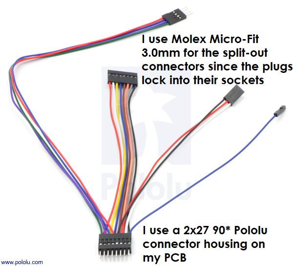
I found a picture of a Pololu harness which looked perfect for what I needed:
Image

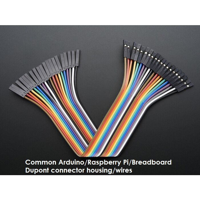
This harness uses common Dupont connecters/wiring which are used on breadboards and Arduino and Raspberry Pi projects. It's very easy to add and remove pins from these; to remove a pin you just need a needle and pull up the locking tab and the pin slides out.
Image

The 2x27 female connector is "strong enough" to hold the connector to the PCB's 2x27 90* connector but the split-out connectors need something stronger so I use Molex Micro-Fit 3.0mm connectors.
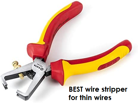
Stripping one end of the Dupont wires for the Molex pins was annoying initially because the wires are very thin and I'd often end up with only 1 or 2 wire strands so I couldn't crimp the Molex pins to them and I wouldn't trust a single wire for the electrical connection either.
After a bit of Googling I found that the following type of wire stripper works best for thin wires so I bought one - it DOES work well for small wires once you've set the screw correctly:
Image

I decided to use a locking connector on the PCB just to be safe.
For a 2x27 pin PCB connector I needed to use a 2x20 pin connector socket and shorten it by one pin so that the locking connector locks down onto the 2x edge pins.
Unfortunately the locking connector takes up almost the entire fascia width so the power input needs to be mounted on the rear fascia.

I used my 3D printer to print custom front and rear fascias for the case:
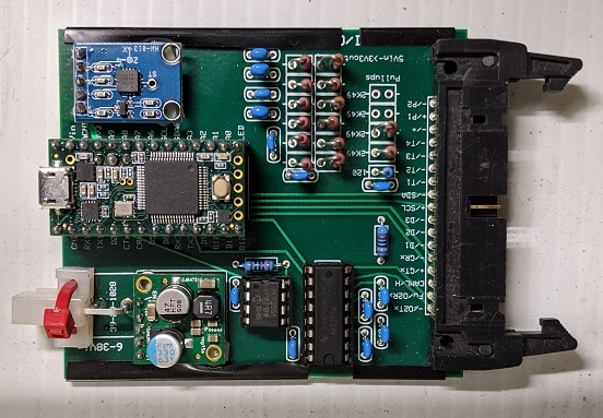
Image
The bottom left PCB daughter board is a Pololu 24-5V converter so the box can be powered by 12V or 5V input sources and won't get too hot.
Users can choose to power the box with 12V or 5V.
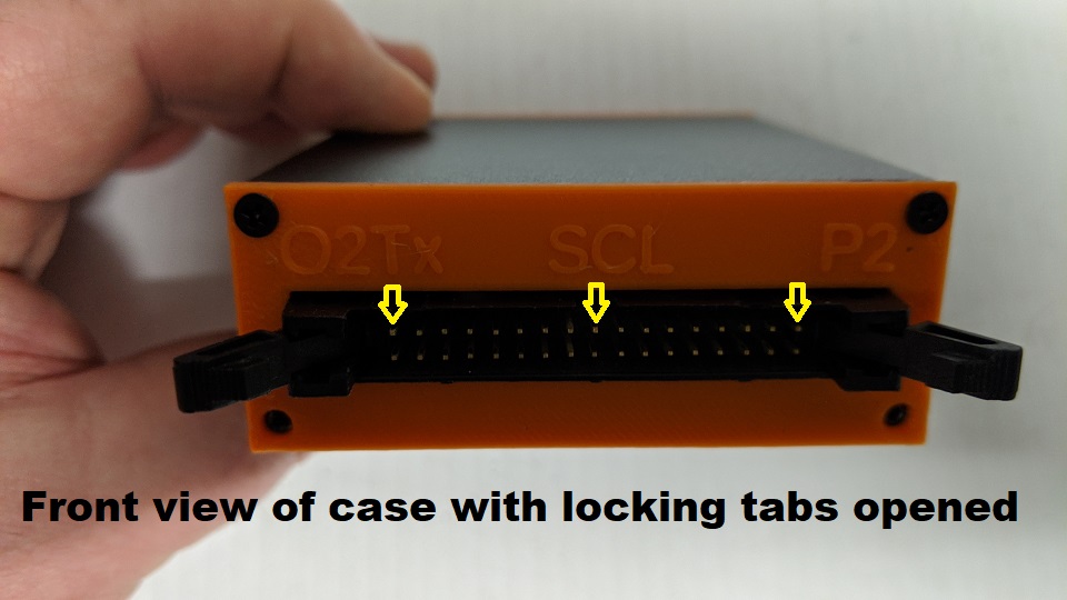
Image
The yellow arrows point to where the printed label aligns to to make it easier when pinning the harness.
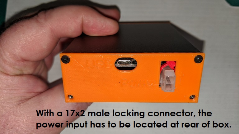
Image

ManiacLachy has been testing my original sensor box and it has been flaky at times, noticeable because the OLED display locks up.
I haven't noticed this on my testbed or in my original car installation but he actually drives his car so is finding different errors.
One of the issues I've suspected is that I use I2C to control the OLED(s) and found out that they should only be used for short distances, < 1x metre.
This means that my sensor box needs to be located as close to the OLED(s) as possible.
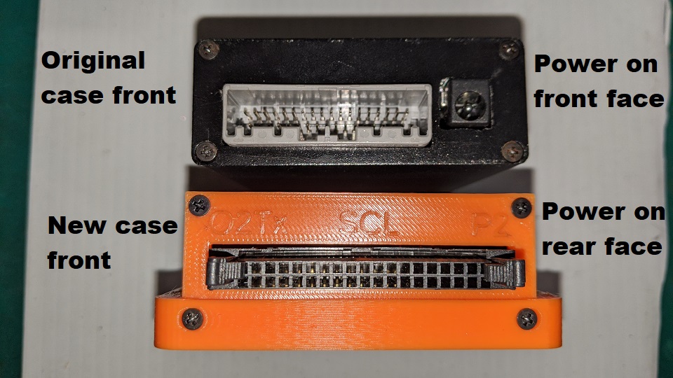
Image
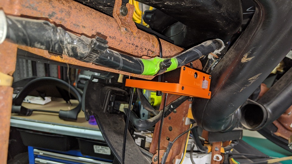
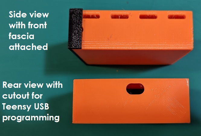
The bottom 3D printed chunk allows the case to sit inside it and has 4x vertical slots for zip-ties to allow it to be mounted to the crash bar behind the cluster.

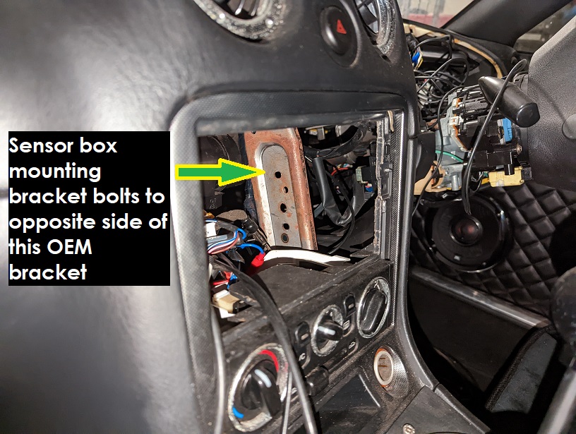
This is where I planned to mount the sensor box:
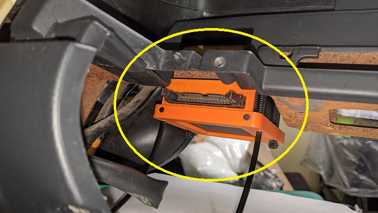
Image
Image

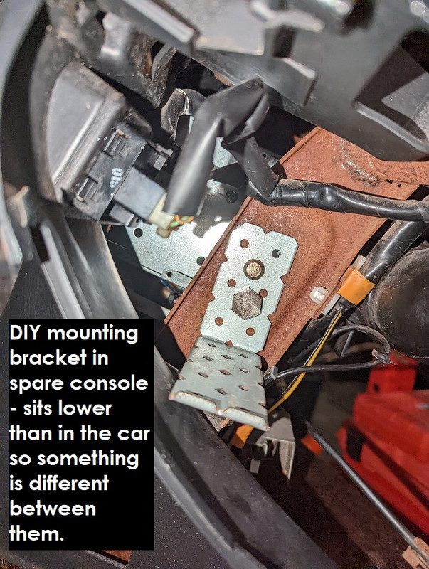
It wasn't too hard to mount this in my spare NB console that I originally bought to test-fit my Android Head Unit but fitting it in the car was a whole different story and accessing the rear power connector was going to be almost impossible!

The previous photo though gave me an idea - I can actually build a bracket to mount the sensor box using that OEM strut in the bottom+middle of the photo - I'm already bolting my DIY Android Head Unit mount there, the bracket can go on the other side!
Don't worry about dying, worry about not living!
Garage Thread: http://www.mx5cartalk.com/forum/viewtopic.php?f=57&t=76716

User avatar
Lokiel
Forum legend
Posts: 4126
Joined: Thu May 28, 2009 2:39 pm
Vehicle: NB SE
Location: Brisbania

Re: Lokiel's "Gina" (2004 Titanium SE)

Postby Lokiel » Sun Oct 30, 2022 11:18 pm

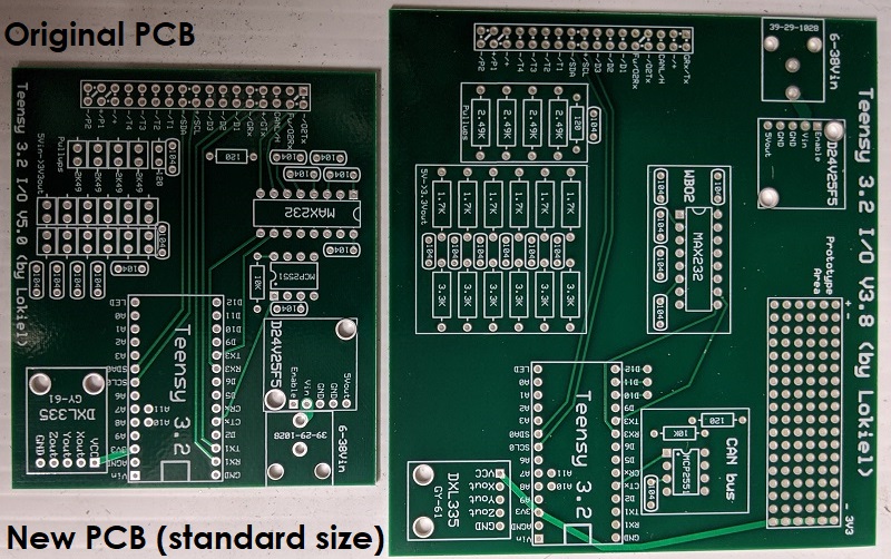
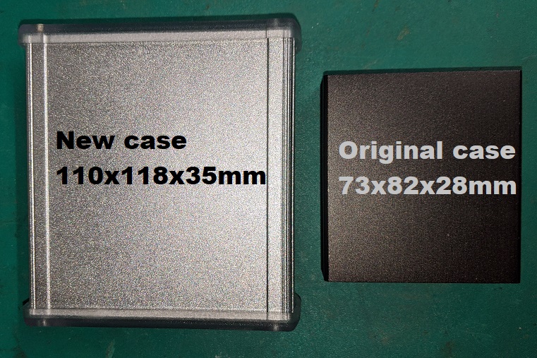
The power connector needed to be moved to the front fascia so I re-designed my board to use a standard-sized DIY PCB since it's larger than my PCB, makes the board cheaper to make and easier to find a case for.

There was so much free space on the board that I added some extra pins for prototype purposes.

Image
Image

Unfortunately this case is WAY too big to mount in an MX5 :(

I decided to ditch the idea of using a locking connector on the 2x27 PCB plug, even only half populated the connection is incredibly strong and has to be "rocked-out slowly" to remove.

Another issue popped up too.

Originally I was using a 10Hz GPS TTL daughter board which meant I had to come up with a way of mounting it.

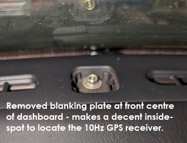
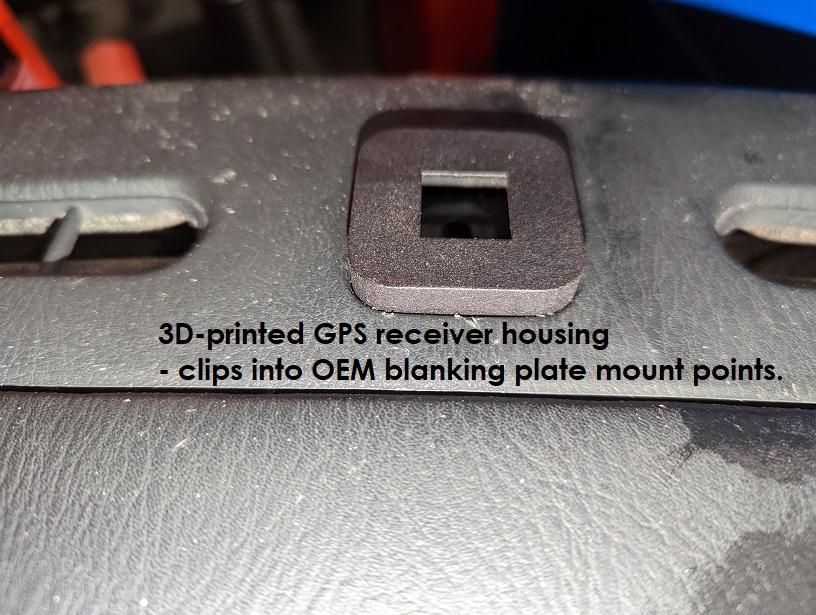
The front-centre of the NB has a square blanking plate that covers a bolt that holds the console to the chassis:
Image

I 3D printed a custom case for the GPS daughter board that mounts into this slot:
Image

Unfortunately the GPS daughter board is too deep and contacted the bolt below it so I'd need to make the case much taller - not a biggie but I didn't want it to be too tall.

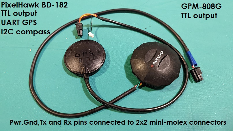
At about that time I noticed that serial 10Hz GPS devices were actually cheaper than the GPS daughter board I was using due to the new popularity of drones.
I have a MAX-232 chip already on my board for the Serial Innovate Wideband O2 input and was only using one of its two TTL-serial converters so could use the other for a serial GPS device.

Image
Serial connectors replaced with Molex Micro-Fit 3mm connectors.

Another bonus of these GPS devices is that they're using the Ublox NEO-M8N chipset.
These chipsets have a custom message, UBX-NAV-PVT, that contains all the data needed for GPS position in a packed digital form.
Like most people, I'd used the NMEA RMC and GGA messages to extract the GPS data I needed which meant I needed to parse BOTH messages, which are in text form, and convert them to the digital format I need.
The UBX-NAV-PVT message is far more efficent.
The "problem" with GPS receivers using the Ublox NEO-M8N chipset was that by default they only generate data at 1Hz despite supporting up to 10Hz.
I found a Ublox NEO-M8 chipset guide on the internet and figured out how to reliably configure the GPS receiver to 10Hz and only output the UBX-NAV-PVT message (so that I didn't receive data I didn't care about anyway).

I'd hoped to be able to create a DIY mount for the serial GPS receivers using the console mouunt point above but their cables are too stiff to easily push down the hole, even when I tried hacking their case to allow the cable to be pulled downward.

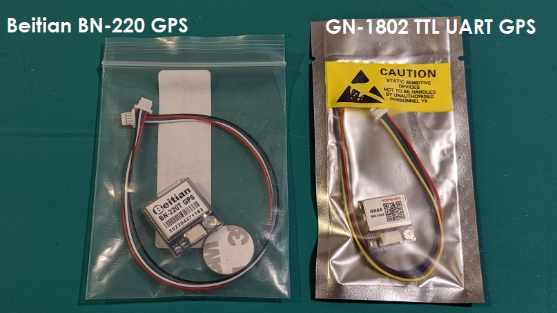
Next up I decided to try just the GPS receiver chips themselves.
Image

These chips are TTL-only so I wouldn't need to use the TTL-serial MAX-232 conversion.
I didn't want to use them initially because I couldn't figure out how to mount them.
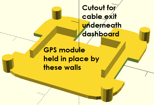
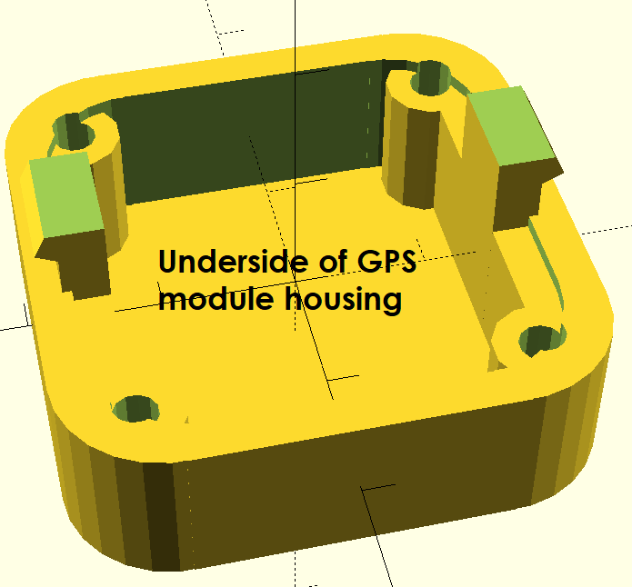
I created a new base for my GPS case that "walled-in" the chip so that it couldn't move around and clipped into the roof.
Image
Image

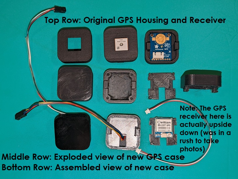
Previous vs new GPS case (previous case printed for me with carbon filament, new one printed by me using PetG filament):
Image
I wanted the top part of the new case to be compatible with either of the GPS chips used so didn't include a cut-out (the cut-outs would need to be off-centre too, towards the front of the car, which would have looked odd). The base needs to be custom but they're quick to print.

... more to come tomorrow
Don't worry about dying, worry about not living!
Garage Thread: http://www.mx5cartalk.com/forum/viewtopic.php?f=57&t=76716

User avatar
bruce
Speed Racer
Posts: 7706
Joined: Fri Apr 25, 2003 11:00 am
Vehicle: NA8 - Turbo
Location: Victoria
Contact:

Re: Lokiel's "Gina" (2004 Titanium SE)

Postby bruce » Mon Oct 31, 2022 11:14 am

I wonder if finding a bolt with a shorter head would have helped ie. fit a big philips head bolt thus reducing the current profile.

User avatar
Lokiel
Forum legend
Posts: 4126
Joined: Thu May 28, 2009 2:39 pm
Vehicle: NB SE
Location: Brisbania

Re: Lokiel's "Gina" (2004 Titanium SE)

Postby Lokiel » Mon Oct 31, 2022 8:44 pm

The "new case" wass "just too big" so I went back to my original PCB design and
* ditched the thought of using a locking connector for the 2x27 pin harness
* moved the power input to the front
* added support for a serial GPS device (using the spare MAX232 Tx/Rx pins)
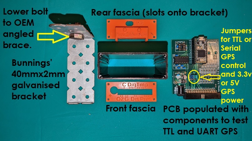
* added a jumper for the harness' GPS power pin so that the GPS device can use either 3.3V or 5V power (many TTL GPS devices only use 3.3V)
* added jumpers for the GPS Tx and Rx pins to define whether TTL or serial data is needed (allows users to use either type)

The PCB is "packed" now so I can't add any more features (which is a good thing, I won't be tempted to make use of any unused pins/features).

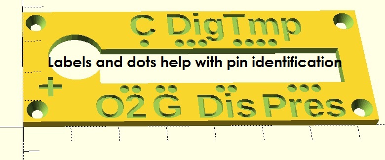
I 3D printed a front fascia for the case to help locate the harness pins:
Image

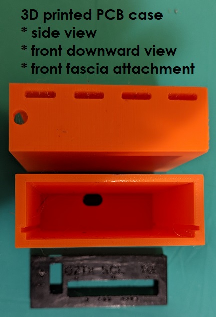
I now had several "old boards" that were still useful but no extra cases for them so I 3D printed a case too:
Image
Image
I use one as an Innovate Wideband O2 simulator to test my new sensor box.
Don't worry about dying, worry about not living!
Garage Thread: http://www.mx5cartalk.com/forum/viewtopic.php?f=57&t=76716

User avatar
Lokiel
Forum legend
Posts: 4126
Joined: Thu May 28, 2009 2:39 pm
Vehicle: NB SE
Location: Brisbania

Re: Lokiel's "Gina" (2004 Titanium SE)

Postby Lokiel » Mon Oct 31, 2022 8:54 pm

... back to that OEM bracket as a mount point for my sensor box:

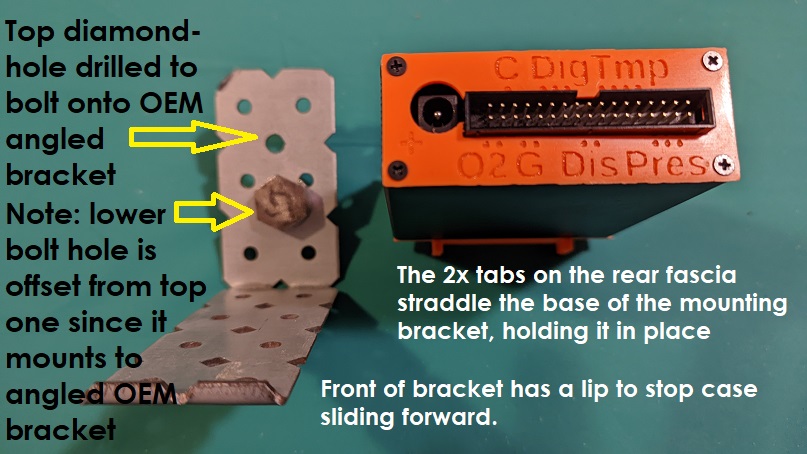
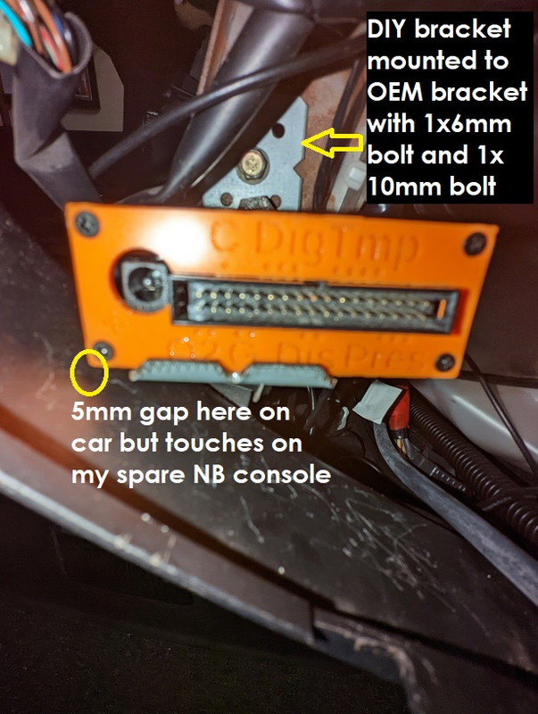
Here's the OEM bracket I plan to mount my sensor box to - I'm already using it to mount my Android Head Unit DIY bracket to so both sides of the OEM bracket will be used:
Image
Image
The photo above should be rotated anti-clockwise a bit since the base of the bracket is actually horizontal to the ground.
The bracket is a simple 40x2mm galvanised bracket from Bunnings, stronger than aluminium with a DIY 90* bend and easy to drill-out the required holes.
Note that the 2x bolts are not lined up vertically because the OEM bracket is slightly angled (see top photo).

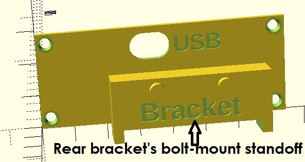
I 3D-printed the rear fascia for the case too.
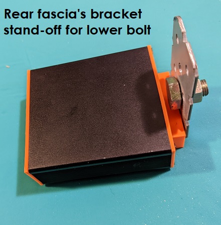
The rear fascia has a standoff block to give clearance to the lower 10mm bolt head as well as a couple of cylinders to slot into the DIY bracket's rear horizontal holes and 2x tabs either side of the rear of the bracket base to help hold the case in place.
The front of the DIY bracket has a small lip to prevent the case moving forward and back.
One or more zip ties around the sides of the case can be used to hold the case permanently to the bracket, easy to install and easy to remove (with a knife).

Image
Image
Image

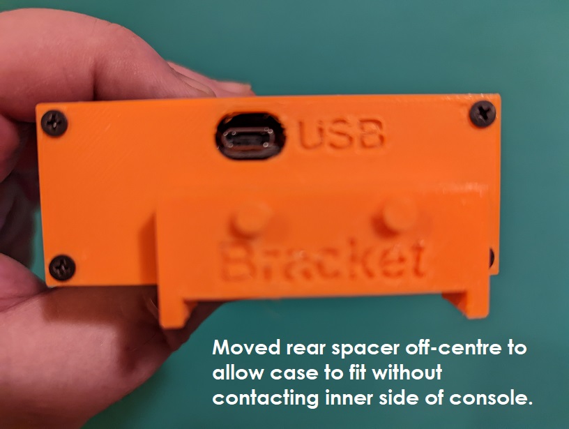
The case ended up contacting the inside of the console so I moved the rear stand-off block off-centre to clear it.
The case is no longer centred on the bracket's base but is still held firmly with the zip-ties.

Image
Image
Image

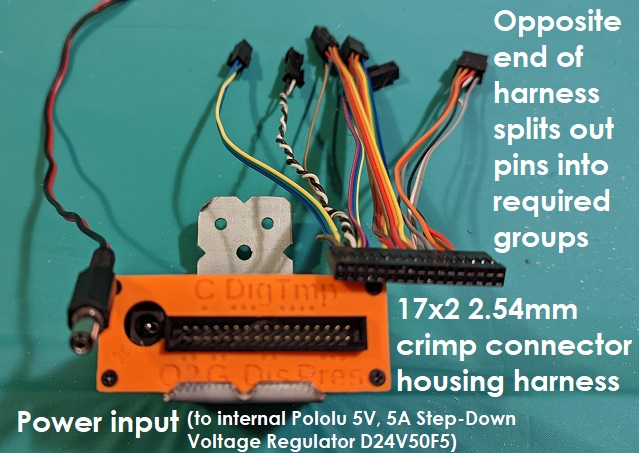
Here's what the harness looks like with almost every pin populated:
Image

I'm now making use of every pin except the pins used for digital switch 1&2 (all wiring to the sensors is in place through to the instrument cluster) so now need to pin those wires for the Molex Micro-Fit connectors to hook up to the Sensor Box harness.
I'm not looking forward to it, especially now that it's summer, and will be buying a heat-shrink label maker for the job to make it easier to identify the wire combinations.

I'm happy with this location, while access is still not "super easy", mounting is straight-forward and subsequent access only requires the panel under the steering wheel to be removed (2 screws on an NB).
Don't worry about dying, worry about not living!
Garage Thread: http://www.mx5cartalk.com/forum/viewtopic.php?f=57&t=76716


User avatar
Lokiel
Forum legend
Posts: 4126
Joined: Thu May 28, 2009 2:39 pm
Vehicle: NB SE
Location: Brisbania

Re: Lokiel's "Gina" (2004 Titanium SE)

Postby Lokiel » Tue Jan 17, 2023 2:19 pm

^
My sister e-mailed this, this morning: https://celebrity.nine.com.au/latest/italian-film-legend-gina-lollobrigida-dies-at-age-95/9d39f2d1-732a-4381-a225-7f9b3b707aa3

95 is "a pretty good innings" and La Lollo had an amazing life - RIP
Don't worry about dying, worry about not living!
Garage Thread: http://www.mx5cartalk.com/forum/viewtopic.php?f=57&t=76716

User avatar
ManiacLachy
Forum Guru
Posts: 3266
Joined: Mon Jan 13, 2014 2:35 pm
Vehicle: NB SE
Location: Brisbane

Re: Lokiel's "Gina" (2004 Titanium SE)

Postby ManiacLachy » Tue Jan 17, 2023 2:21 pm

She sure did from the sounds of it, a firecracker personality to go with her looks!

User avatar
greenMachine
Forum Guru
Posts: 4053
Joined: Thu Apr 24, 2003 11:00 am
Vehicle: NB SE
Location: Sports car paradise - Canberra
Contact:

Re: Lokiel's "Gina" (2004 Titanium SE)

Postby greenMachine » Tue Jan 17, 2023 2:59 pm

She was certainly more than good looking with a good figure!

RIP La Lollo!! :(

:mrgreen:
I never met a horsepower I didn't like (thanks bwob)

Build thread

NB SE - gone to the dark side (and loving it 8) )

User avatar
Lokiel
Forum legend
Posts: 4126
Joined: Thu May 28, 2009 2:39 pm
Vehicle: NB SE
Location: Brisbania

Re: Lokiel's "Gina" (2004 Titanium SE)

Postby Lokiel » Wed Feb 15, 2023 10:12 pm

I've had time recently to work on the next generation of my sensor box and wasn't too keen on doing all that soldering again,
Here's an almost fully-populated version of the previous generation:
Image

I also discovered that the the Gyro daughter-board I was using was only designed to be read at 1Hz and I want to read it at 10Hz so that I can log GPS position and G-force at the same point in time.

I decided to re-do my board using Easy EDA from http://jlcpcb.com/, a tool+company that supports "Pick & Place" so that I can get the board manufactured with as many components already soldered in place as possible. It's a LOT more intricate than the ExpressPCB tool I was using and took ~3 weeks to design the board, mostly learning the tool.

The most expensive components I'm using are the Teensy3.2, DC 24->5V daughter-board (converts any input voltage between 24V and 5V to 5V for the Teensy3.2 and sensors) and Gyro daughter-board.

Rather than solder the Teensy3.2 directly to the board, I solder female pin headers to the board and plug the Teensy 3.2 into them, that way I can easily replace the Teensy3.2 if it dies or re-use it on other boards/projects.

To save $$$ on the DC 24-5V converter and Gyro daughter-boards, I needed to figure out what components were needed and mount them directly on the new board so that took time too and I learned a LOT.

Since I've already got heaps of CAN transceiver and RS232 chips+socket-caddies (it wasn't much more expensive to buy 50 via Ali-Express than 5 on e-Bay) I decided to use them rather than purchasing new ICs and soldering them to the board (24x manual solders per board isn't too bad).

I completed the board tonight and placed an order for the PCB build and assembly.

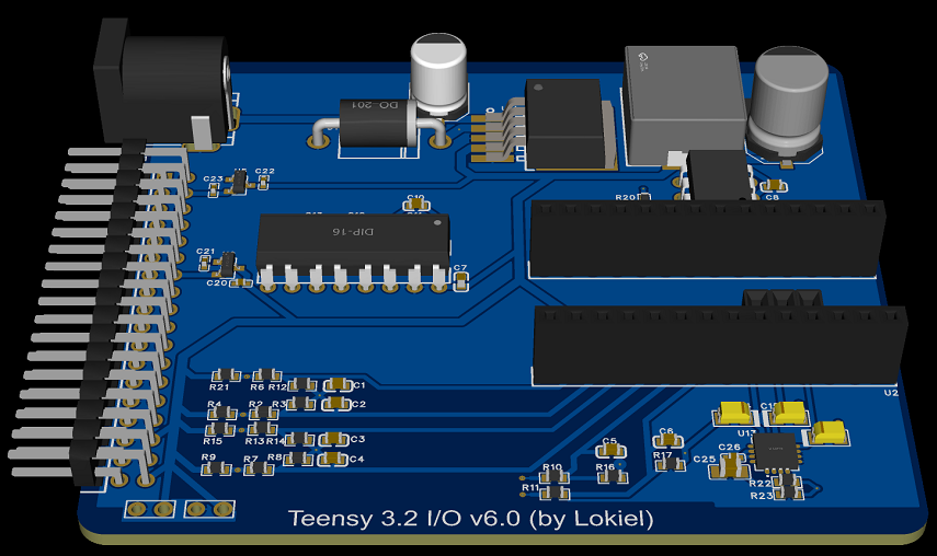
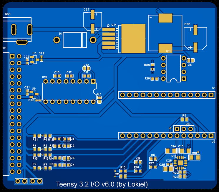
Here's the 3D and 2D views of the new board that were generated by the tool:
Image
Image

The minimum order is 5x boards and even with the extra components ordered and soldered onto the board, it's 1/3 the price of 3x ExpressPCB boards-only, including S&H - definitely worth learning how to use EASY EDA.

JCLPCB also have a 3D printing service too so I'll probably use that in future too to produce "professional" prints for the display housings, GPS housings and even cases (they provide resin options as well as carbon filament and metallic options).
Don't worry about dying, worry about not living!
Garage Thread: http://www.mx5cartalk.com/forum/viewtopic.php?f=57&t=76716


Return to “MX5 Garage Chat”

Who is online

Users browsing this forum: No registered users and 17 guests