The Black Rat
Moderators: timk, Stu, -alex, miata, StanTheMan, greenMachine, ManiacLachy, Daffy, zombie, Andrew, The American, Lokiel
- ManiacLachy
- Engaged
- Posts: 3315
- Joined: Mon Jan 13, 2014 2:35 pm
- Vehicle: NB SE
- Location: Brisbane
Re: The Black Rat
Some execellent progress being made! The bracket for the ignition modules and the ECU mount look really good. And the IC piping looks great and good to know clarance isn't an issue.
Seriously, great work! Can't wait to see it running soon.
After the Rat is up and running wil you turn your attention back on the Mouse and make him streetable?
Seriously, great work! Can't wait to see it running soon.
After the Rat is up and running wil you turn your attention back on the Mouse and make him streetable?
-
The American
- Forum Guru
- Posts: 1542
- Joined: Fri Jun 29, 2012 9:23 pm
- Vehicle: NB8B - Turbo
- Location: Brisbane, Qld. Previously Perth WA
- Contact:
Re: The Black Rat
ManiacLachy wrote:After the Rat is up and running will you turn your attention back on the Mouse and make him streetable?
Probably, but I do enjoy driving it mostly as it is. The main things I may do is raise it to a more useable height, and switch the tyres out for something that will cope with longer drives.
- greenMachine
- Forum Guru
- Posts: 4185
- Joined: Thu Apr 24, 2003 11:00 am
- Vehicle: NB SE
- Location: Sports car paradise - Canberra
- Contact:
Re: The Black Rat
Good progress, looking forward to completion (as if these cars are ever complete! 
 ),
),
One Q - what is that mounted to the engine bay side of the radiator - oil cooler?

One Q - what is that mounted to the engine bay side of the radiator - oil cooler?
I never met a horsepower I didn't like (thanks bwob)
Build thread
NB SE - gone to the dark side (and loving it )
)
Build thread
NB SE - gone to the dark side (and loving it
-
The American
- Forum Guru
- Posts: 1542
- Joined: Fri Jun 29, 2012 9:23 pm
- Vehicle: NB8B - Turbo
- Location: Brisbane, Qld. Previously Perth WA
- Contact:
Re: The Black Rat
greenMachine wrote:Good progress, looking forward to completion (as if these cars are ever complete!
),
One Q - what is that mounted to the engine bay side of the radiator - oil cooler?
That is an oil cooler. After the offroad excursion in the White Mouse that took out the corner mounted oil cooler, I decided a more 'inboard' arrangement would be better. I also don't like the rack mounted 'low mount' because of how exposed it seems and because that space will probably be covered by a splitter in the future.
That really does not leave too many near-engine locations for a cooler except for behind the radiator (or without completely rearranging the with a V-mount for the radiator or something like that). The lower port of the oil cooler interferes with the bottom of the radiator support bracket and there is still some work to do to solve that. The cooler is sized to take into account that it is not going to see fresh air directly.
- greenMachine
- Forum Guru
- Posts: 4185
- Joined: Thu Apr 24, 2003 11:00 am
- Vehicle: NB SE
- Location: Sports car paradise - Canberra
- Contact:
Re: The Black Rat
I did the same. Mine is not super large (got to leave room for a fan), and I have not got it wired into the ECU yet, let alone logged temps.
One of the plusses of that location is that the coolant heats the oil (via the hot air coming off the radiator). Gary Stewart drummed into me the necessity of looking after the engine until it (the oil, not just the coolant) warmed up - to 80*C. On a frosty morning at Wakefield Park, that was a lot easier said than done - until I installed a laminova oil/coolant heat exchanger on the radiator outlet. This is as close as I can get to that setup.
I'd like to mount it in front of the rad, but it is just too crowded in there.
I never met a horsepower I didn't like (thanks bwob)
Build thread
NB SE - gone to the dark side (and loving it )
)
Build thread
NB SE - gone to the dark side (and loving it
-
The American
- Forum Guru
- Posts: 1542
- Joined: Fri Jun 29, 2012 9:23 pm
- Vehicle: NB8B - Turbo
- Location: Brisbane, Qld. Previously Perth WA
- Contact:
This is exhausting!


It's a 3" system from dump pipe to tip, with a 100 cel cat, resonator in the mid pipe and muffler at the back. It has v-band connections except for the bottom of the dump pipe (where a V-band would have taken up a bit too much space.
I was a bit worried about how this would all fit, with the tunnel narrowed by the floor pan changes, but it all has plenty of clearance.
- bruce
- Speed Racer
- Posts: 7807
- Joined: Fri Apr 25, 2003 11:00 am
- Vehicle: NA8 - Turbo
- Location: Victoria
- Contact:
-
The American
- Forum Guru
- Posts: 1542
- Joined: Fri Jun 29, 2012 9:23 pm
- Vehicle: NB8B - Turbo
- Location: Brisbane, Qld. Previously Perth WA
- Contact:
Anxious 30 seconds
The car will have some wiring done next week (I’m not game yet, and don’t have the knowledge) including wiring in the coils. For them to test the coils they want to be able to crank the engine over. For this, the engine needs oil.
With the spark plugs out, and the feed line to the turbo disconnected and running into a glass jar, I cranked it over until the oil flowed into the jar. It was probably under 20 seconds of cranking, but those seconds were long!
No big deal no doubt, but as an amateur who doesn’t want to wreck anything, it was a ‘phew’ moment.
I’ve started making up the oil lines for the remote filter and cooler, bled the clutch slave cylinder (have replaced the epic factory clutch line with HEL flexible line), and have begun configuring the ECU for first start (much more reading and learning needed here).
- plohl
- Racing Driver
- Posts: 1922
- Joined: Wed Oct 14, 2009 12:13 am
- Vehicle: NA8
- Location: Brisbane
Re: The Black Rat
Before running my engines on the engine dyno, we've feed oil into the engine using a catch can like container and an air compression. With the valve cover off you can ensure the heads getting oil, and pressurise the system before you start cranking. I've see this highlight two issues on another engine -
1st, head gasket wasn't on right so no oil getting to the head,
2nd, it was vvt head with race cams but they hadn't seal the oil feeds for the vvt, so once the gasket was fixed, oil vomited from the front of the head.
1st, head gasket wasn't on right so no oil getting to the head,
2nd, it was vvt head with race cams but they hadn't seal the oil feeds for the vvt, so once the gasket was fixed, oil vomited from the front of the head.
Cheers,
plohl
plohl
-
The American
- Forum Guru
- Posts: 1542
- Joined: Fri Jun 29, 2012 9:23 pm
- Vehicle: NB8B - Turbo
- Location: Brisbane, Qld. Previously Perth WA
- Contact:
Intake fitted
The White Mouse has its intake routed out of the engine bay into the bumper space through an enlarged version of the hole behind the headlight. I've done the same with this car and it just fits around the power steering reservoir using a 2.5" to 3" silicon elbow and a 90 degree aluminium mandrel bend. You can't see it in the photos but there is a length of 3mm x 25mm flat bar twisted to pick up a threaded bolt hole and and welded to the side of the pipe, to secure it.


The current list of jobs:
The oil/separators is a puzzle. I have a spot that I could fit an adequate vented can, but it won't have the 2l capacity requirement that the car will need for log booking. I don't want to plumb the can back to the intake (which I believe waives the 2l capacity requirement). The only clear spaces in the engine bay that might accept 2l in a simple shape right now, are (1) directly behind the radiator or (2) in the space where the wiper mechanism operates. There could be sufficient space above the intercooler, inside one of the guards or in the drivers side bumper front corner.
Does anyone have any ínnovative' spots for their 2l catch can?


The current list of jobs:
- - Remove the driver's side radiator support bracket and modify to create clearance for an oil cooler hose
- Refit radiator, fill and bleed coolant
- Make up remaining oil lines
- Stagger cut and wrap back unused fan, stock coil and EGR wiring
- Design and fabricate oil/air separator(s)
The oil/separators is a puzzle. I have a spot that I could fit an adequate vented can, but it won't have the 2l capacity requirement that the car will need for log booking. I don't want to plumb the can back to the intake (which I believe waives the 2l capacity requirement). The only clear spaces in the engine bay that might accept 2l in a simple shape right now, are (1) directly behind the radiator or (2) in the space where the wiper mechanism operates. There could be sufficient space above the intercooler, inside one of the guards or in the drivers side bumper front corner.
Does anyone have any ínnovative' spots for their 2l catch can?
-
The American
- Forum Guru
- Posts: 1542
- Joined: Fri Jun 29, 2012 9:23 pm
- Vehicle: NB8B - Turbo
- Location: Brisbane, Qld. Previously Perth WA
- Contact:
Oil/Air Separator
I had a first attempt at making a catch can today. It's not finished yet, and I still need to weld in the baffling, attach the inlets and a vent, and figure out a drain (yes, nowhere near done!) but the overall shape and fit is fairly sorted.
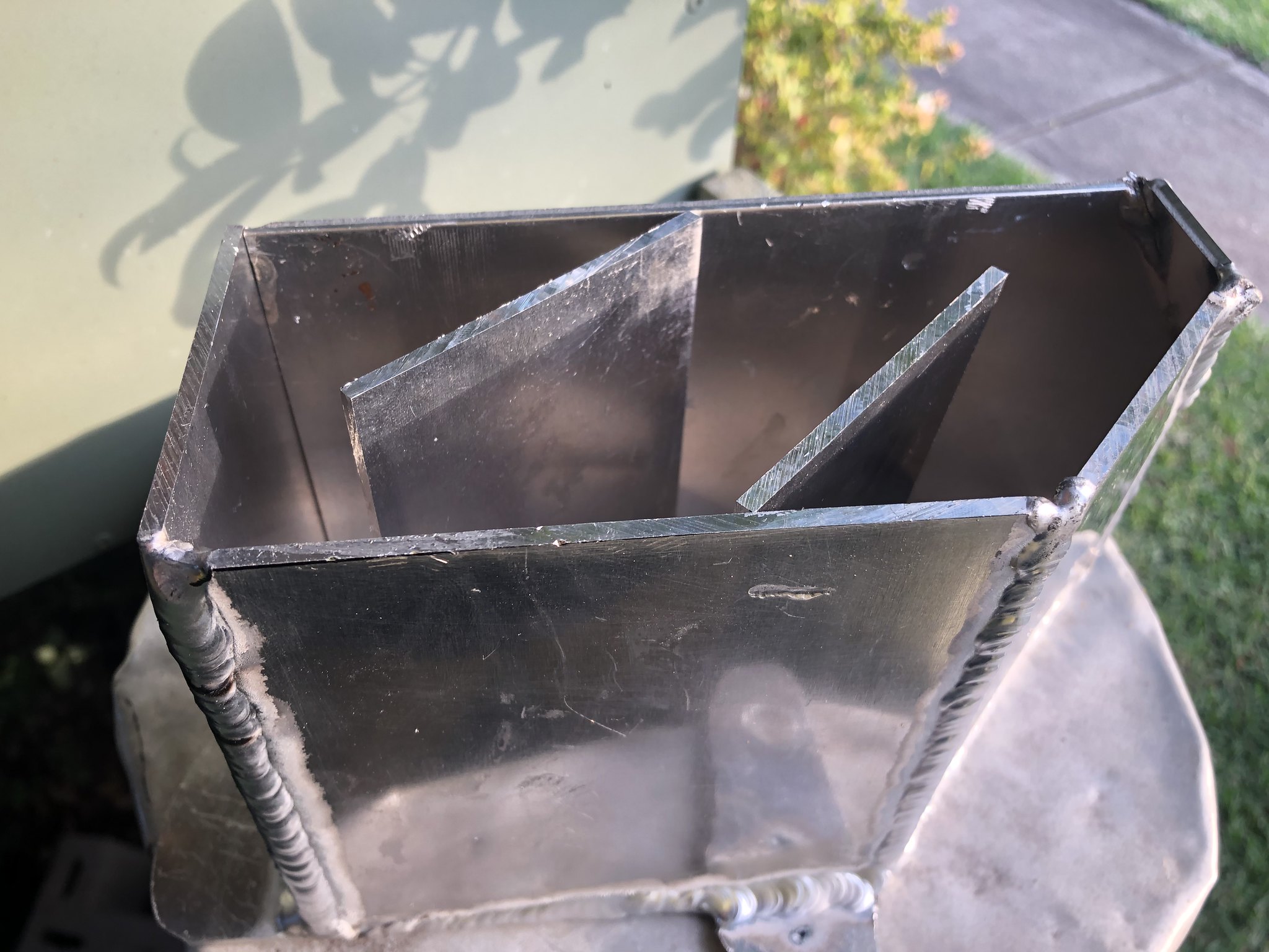
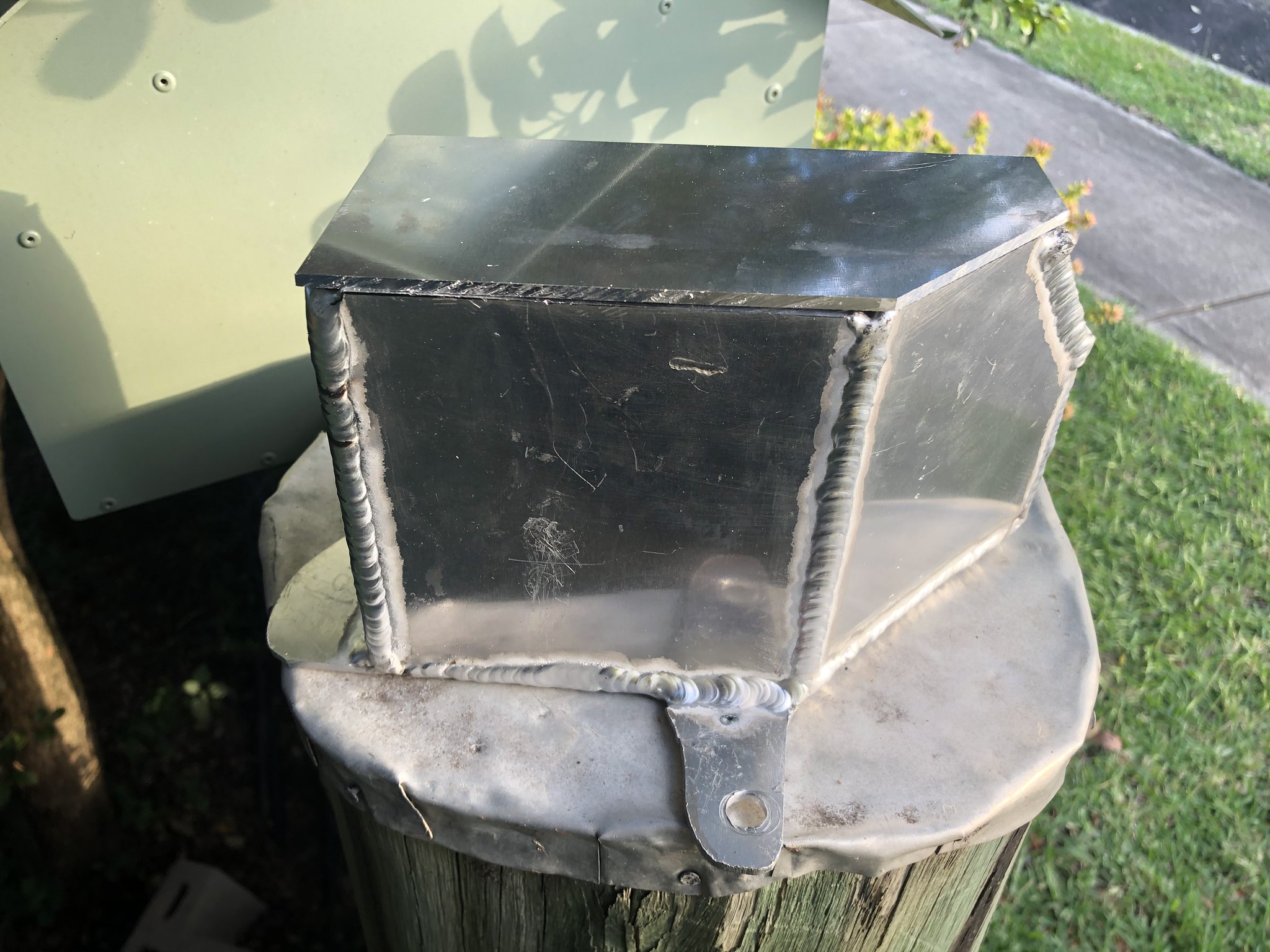
This is where it fits in the engine bay. It shares a bolt with the power steering reservoir, and there will be a second bolt and nutsert underneath the intake pipe.

In terms of total capacity, it is about 1.5 litres - not quite the magic 2l.
In terms of baffling, I am hoping to keep it fairly simple and allow the air to slow turn back on itself a few times. The inlets will be located just above the little leg with the hole for the powersteering reservoir bolt. Any thoughts on the baffling?
The drain will probably be through a port on the bottom which I think should pass comfortably through the sheet metal into the same area where the intake filter sits: Empty catch can, clean and reoil filter perhaps?


This is where it fits in the engine bay. It shares a bolt with the power steering reservoir, and there will be a second bolt and nutsert underneath the intake pipe.

In terms of total capacity, it is about 1.5 litres - not quite the magic 2l.
In terms of baffling, I am hoping to keep it fairly simple and allow the air to slow turn back on itself a few times. The inlets will be located just above the little leg with the hole for the powersteering reservoir bolt. Any thoughts on the baffling?
The drain will probably be through a port on the bottom which I think should pass comfortably through the sheet metal into the same area where the intake filter sits: Empty catch can, clean and reoil filter perhaps?
-
Nevyn72
- Speed Racer
- Posts: 2207
- Joined: Fri Nov 29, 2013 8:51 am
- Vehicle: ND - RF
- Location: Sydney
Re: The Black Rat
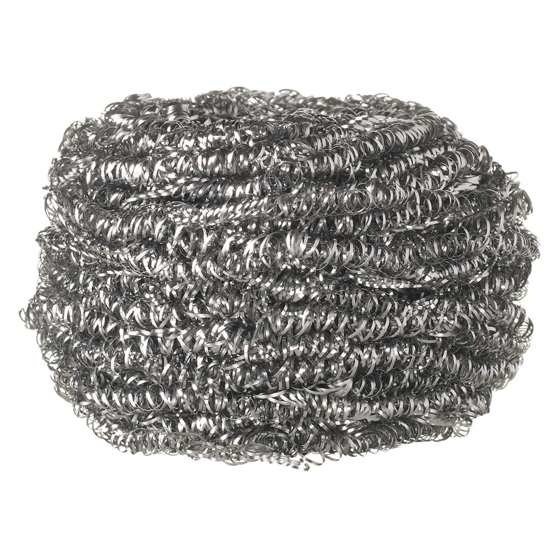
In terms of baffling, I am hoping to keep it fairly simple and allow the air to slow turn back on itself a few times. The inlets will be located just above the little leg with the hole for the powersteering reservoir bolt. Any thoughts on the baffling?
Just fill the can with some of this, loosely packed...
"A Convertible has a top you can put down when the weather's nice...... A Roadster has a top you can put up when the weather's bad."
-
The American
- Forum Guru
- Posts: 1542
- Joined: Fri Jun 29, 2012 9:23 pm
- Vehicle: NB8B - Turbo
- Location: Brisbane, Qld. Previously Perth WA
- Contact:
Finished oil/air separator
Progress has slowed a little with other non-car things needing my spare focus and time.
I did get around to finishing off (98%) the catch can arrangement, mounting it and putting together the hoses from the valve cover.
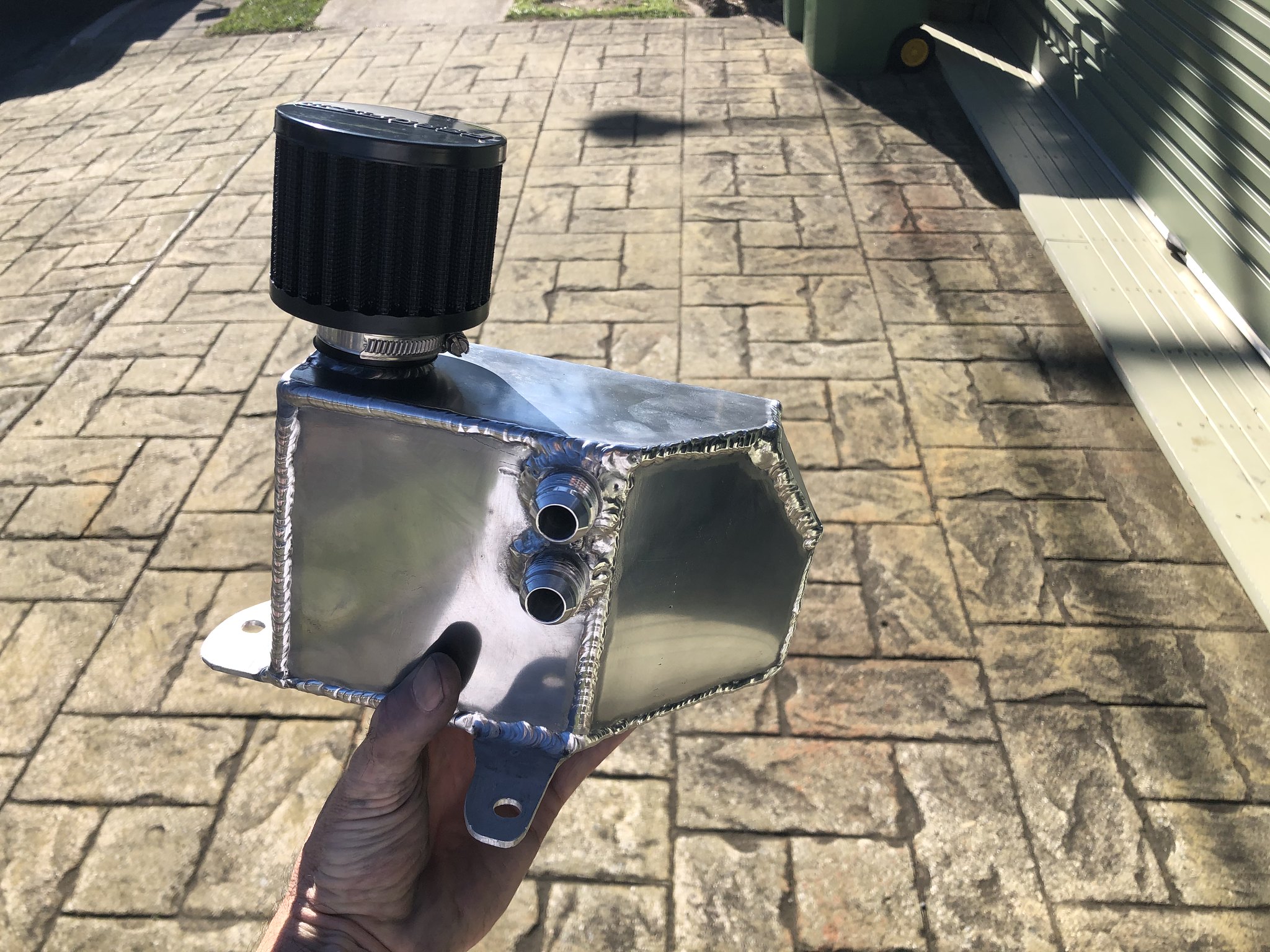
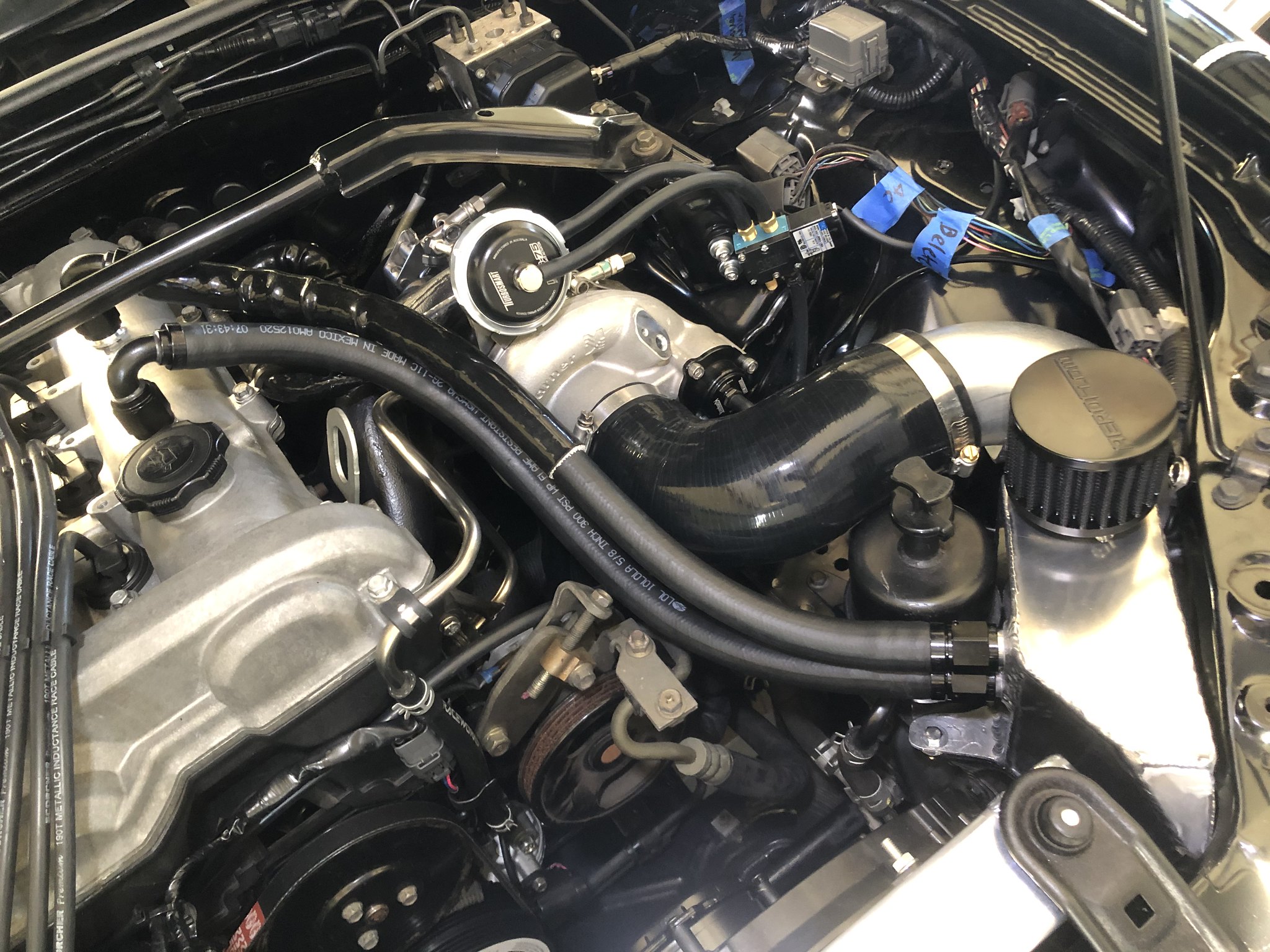
Not shown in the images is a 3/8 barb which is welded to the underside on the opposite corner to the inlets and directly below the vent. This pokes through into the same area that the air intake filter sits, and will be plumbed to a stopcock mounted somewhere (probably) in the engine bay. I have not found a source for small enough valve/tap/stopcock yet.
In terms of flow, the two vents are -10an and there are two 10mm holes drilled in the 'tiny hole mod' location of the valve cover baffling. The vent port on the separator is 32mm. This should be overkill?
My TIG-ing is gradually improving, although I found the weld-on fittings tricky to get heat into and see while not dipping the tungsten in...
I did get around to finishing off (98%) the catch can arrangement, mounting it and putting together the hoses from the valve cover.


Not shown in the images is a 3/8 barb which is welded to the underside on the opposite corner to the inlets and directly below the vent. This pokes through into the same area that the air intake filter sits, and will be plumbed to a stopcock mounted somewhere (probably) in the engine bay. I have not found a source for small enough valve/tap/stopcock yet.
In terms of flow, the two vents are -10an and there are two 10mm holes drilled in the 'tiny hole mod' location of the valve cover baffling. The vent port on the separator is 32mm. This should be overkill?
My TIG-ing is gradually improving, although I found the weld-on fittings tricky to get heat into and see while not dipping the tungsten in...
- greenMachine
- Forum Guru
- Posts: 4185
- Joined: Thu Apr 24, 2003 11:00 am
- Vehicle: NB SE
- Location: Sports car paradise - Canberra
- Contact:
Re: Oil/Air Separator
The American wrote:The drain will probably be through a port on the bottom which I think should pass comfortably through the sheet metal into the same area where the intake filter sits: Empty catch can, clean and reoil filter perhaps?
I just put a screw-on cap on mine. It needs emptying rarely and it has proven cheap, simple and workable.
I never met a horsepower I didn't like (thanks bwob)
Build thread
NB SE - gone to the dark side (and loving it )
)
Build thread
NB SE - gone to the dark side (and loving it
-
The American
- Forum Guru
- Posts: 1542
- Joined: Fri Jun 29, 2012 9:23 pm
- Vehicle: NB8B - Turbo
- Location: Brisbane, Qld. Previously Perth WA
- Contact:
Turbo Heat Shield
Behold cringe worthy first attempts at TIG on stainless.
But it will work!
I bought some Bunnings spec 0.8mm 316 stainless sheet and attempted making a heat shield for the turbo and down pipe area. My main concern is the ABS unit.
I have hand shears and a vice based 90 degree folder that is 125mm wide - workable but not quick/easy. I also used a bead roller to add some stiffness to the flat panels where these could be accessed with the tool.


Again, this was also my first proper attempt at welding thin stainless, and I was mostly done before I'd worked out that I was attempting to weld with too low an amperage, leading to a slow speed and too much heat getting into the sheet. Thankfully, most of the welding is not visible once it is fitted to the car. I am not entirely happy with how this turned out, and may have another go at it with a view to getting more coverage over the top of the turbine housing.
But it will work!
I bought some Bunnings spec 0.8mm 316 stainless sheet and attempted making a heat shield for the turbo and down pipe area. My main concern is the ABS unit.
I have hand shears and a vice based 90 degree folder that is 125mm wide - workable but not quick/easy. I also used a bead roller to add some stiffness to the flat panels where these could be accessed with the tool.


Again, this was also my first proper attempt at welding thin stainless, and I was mostly done before I'd worked out that I was attempting to weld with too low an amperage, leading to a slow speed and too much heat getting into the sheet. Thankfully, most of the welding is not visible once it is fitted to the car. I am not entirely happy with how this turned out, and may have another go at it with a view to getting more coverage over the top of the turbine housing.
Who is online
Users browsing this forum: No registered users and 7 guests


