Wiring advice for aftermarket sensors

Audio, Electronics and Lighting questions and answers

Moderators: timk, Stu, zombie, Andrew, -alex, miata

User avatar
Roadrunner
coyotes after you
Posts: 1111
Joined: Tue Nov 06, 2012 9:02 pm
Vehicle: NB SE
Location: Newcastle

Wiring advice for aftermarket sensors

Postby Roadrunner » Fri Jul 05, 2019 1:45 pm

Hi all, just after a bit of advice from the experts on something i've never ventured into before - wiring and taping into ecu connections. (looking at you Magpie and Lokiel :D )

Looking at adding oil pressure sensor and oil temp sensor to the ECU for monitoring and engine protections etc and just wanted to make sure I have this right as per the photo below.

Oil Pressure sensor:
Sig - 4X pin
5V - tap into 5L wire
Ground - tap into 5O wire

Fluid temps sensors seem to only have 2 wires (and no polarity?) so I assume I connect one wire to 4Z and other wire also to 5O?

And lastly what is best practice for tapping in to existing ECU cables? Butt crimp or solder?

Image
MeepMeep

Magpie
Speed Racer
Posts: 7468
Joined: Fri Feb 11, 2011 12:49 pm
Vehicle: NA6
Location: Purga, QLD

Re: Wiring advice for aftermarket sensors

Postby Magpie » Fri Jul 05, 2019 2:01 pm

What ECU are you using?

Are the air/fluid sensors Denso type

NEVER SOLDER, NEVER USE VAMPIRE CLIPS

Use Deutsch connectors

User avatar
StanTheMan
Forum legend
Posts: 6824
Joined: Thu Apr 24, 2003 11:00 am
Vehicle: NA6
Location: Balgowlah

Re: Wiring advice for aftermarket sensors

Postby StanTheMan » Fri Jul 05, 2019 2:53 pm

What’s wrong with soldering?


Sent from my iPhone using Tapatalk
Satans Ride called F33nix the resurrected NA6

Magpie
Speed Racer
Posts: 7468
Joined: Fri Feb 11, 2011 12:49 pm
Vehicle: NA6
Location: Purga, QLD

Re: Wiring advice for aftermarket sensors

Postby Magpie » Fri Jul 05, 2019 3:07 pm

StanTheMan wrote:What’s wrong with soldering?

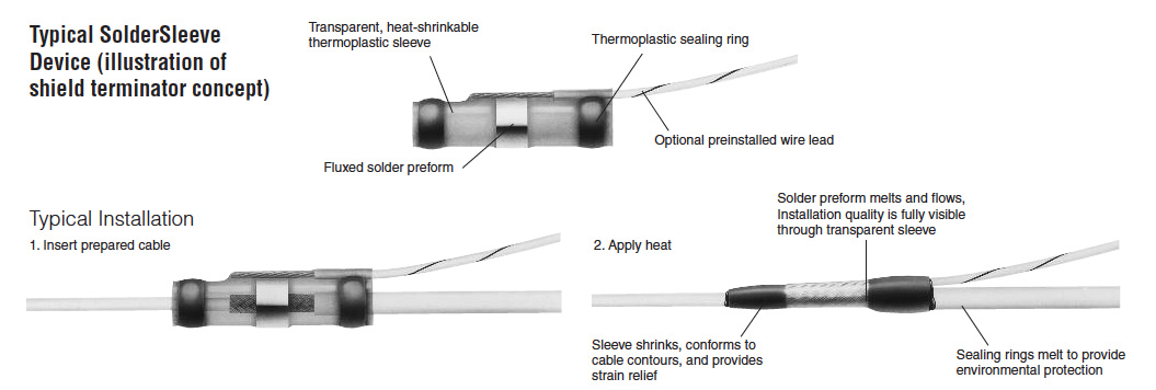
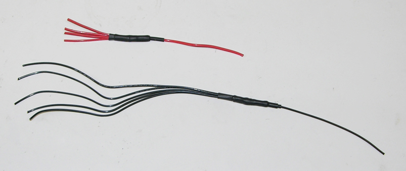
It cracks... let us not go down this can of worms. However, solder sleeves are acceptable

Image

Have a look here for options https://www.motorsportelectrics.com.au/

You can also use these

User avatar
Roadrunner
coyotes after you
Posts: 1111
Joined: Tue Nov 06, 2012 9:02 pm
Vehicle: NB SE
Location: Newcastle

Re: Wiring advice for aftermarket sensors

Postby Roadrunner » Fri Jul 05, 2019 3:25 pm

Adaptronic Modular PNP. Has dedicated inputs for oil Temp and Pressure.
Probably use this sensor (comes with the connector) but open to suggestions: https://www.efisolutions.com.au/stainle ... -ps~127222

When you say only use deutsch connectors, is that only if the sensor has a pigtail or are you suggesting the splice to the ECU sensor ground cable should be a deutsch connector? Do they make 2 into 1 connectors or have I misunderstood?
I'd run a new cable from the sensor connector pins to the ECU pin. All tutorials I've seen so far use butt or open crimps and heatshrink to tap into the required cables just before the ECU connector, but again, open to all advice.
https://www.youtube.com/watch?v=cWkLgkqMVfY

I like the look of the Mini crimp splices. I'll check out that website too. Thanks.

The wiring schematic is all good though?
Last edited by Roadrunner on Fri Jul 05, 2019 3:37 pm, edited 1 time in total.
MeepMeep

User avatar
Roadrunner
coyotes after you
Posts: 1111
Joined: Tue Nov 06, 2012 9:02 pm
Vehicle: NB SE
Location: Newcastle

Re: Wiring advice for aftermarket sensors

Postby Roadrunner » Fri Jul 05, 2019 3:58 pm

MeepMeep

Magpie
Speed Racer
Posts: 7468
Joined: Fri Feb 11, 2011 12:49 pm
Vehicle: NA6
Location: Purga, QLD

Re: Wiring advice for aftermarket sensors

Postby Magpie » Fri Jul 05, 2019 6:08 pm

OK so you are adding wires/sensors to the ECU loom, not splicing into an existing....

I assume that you will be running the length of wire required from the ECU pin to the sensor? Will you be using a bulkhead connector?

To split the 5v and ground, depending on how many other sensors you are powering you may need to do something like this. Also plan for the future...

Image

Planning for the future helps you avoid things like this...
Image

Have a read of this, will not take long
https://www.rbracing-rsr.com/wiring_ecu.html

User avatar
Lokiel
Forum legend
Posts: 4126
Joined: Thu May 28, 2009 2:39 pm
Vehicle: NB SE
Location: Brisbania

Re: Wiring advice for aftermarket sensors

Postby Lokiel » Fri Jul 05, 2019 6:47 pm

Your pressure sensor seems OK - DON'T buy any pressure sensor under A$100, they're usually crap Chinese ones.

You will need to configure your ECU to start reading those new inputs too (Hint: Use that linear table shown in your Oil temperature pictures and use the correct table data for your temperature sensor - it's NOT linear and they're NOT all calibrated the same).
I need to double-check the temperature sensor though for connections but polarity DOESN'T matter for thermistors (I can't remember if you need to connect it to 5V or GND - logic says it should be 5V since GND can be provided by the threading but for some reason I remember it as needing GND).

Vampire clamps on thin wires are a bad idea since they'll eventually break them and you'll end up with 2 sensors that no longer work if you're tapping off an existing sensor.
I have used them to tap power+GND from my power windows for my Wideband O2 heater element since those are VERY thick copper wires - still best NOT to use them anywhere but this was low-risk and I needed to finish the job quickly.

Have a look a Soviet's thread on MT.net, starting at post#1977 on https://www.miataturbo.net/build-threads-57/soviet-russia-car-build-you-61522/page33/ He uses a proper crimping tool (I bought this same one and it's bloody good) and crimps for specific wire gauges (I've got a bunch of these too).
OEM uses crimps for joining wires so you should too - there's less chance of them breaking (when you solder thin wires, it can make them more susceptible to breaking/snapping at the solder point) Just make sure you insulate them after to avoid shorts.
In my SP23, for the audible reversing sensors, I used the reverse lights for a source of power and GND. I stripped away the insulation where I wanted to tap to, crimped my new wires to those points using the appropriate crimp and taped them up for insulation. This left the original wires intact, was easy to do and looked OK.

The solder sleeves are a good idea since they provide extra strength around the solder point and insulation - I've used these in places.

Finding small wire crimps can be hard but you can DIY them by cutting the tips off existing spare pins you may have lying around.
Also for small wire pins, get a suitable crimping tool - the Supercheap one used for bullet/spade connectors is way too big and clumsy.
Don't worry about dying, worry about not living!
Garage Thread: http://www.mx5cartalk.com/forum/viewtopic.php?f=57&t=76716

Magpie
Speed Racer
Posts: 7468
Joined: Fri Feb 11, 2011 12:49 pm
Vehicle: NA6
Location: Purga, QLD

Re: Wiring advice for aftermarket sensors

Postby Magpie » Fri Jul 05, 2019 7:08 pm

I cannot give specific wiring advice as I run a Haltech...

Also pressure sensors must NOT be mounted to the engine, they are very susceptible to vibration.

Mount the sensor on the chassis and run a line to the sensor

Image

User avatar
Lokiel
Forum legend
Posts: 4126
Joined: Thu May 28, 2009 2:39 pm
Vehicle: NB SE
Location: Brisbania

Re: Wiring advice for aftermarket sensors

Postby Lokiel » Sat Jul 06, 2019 3:38 pm

... chased up my original confusion with the thermistor wiring.

Connection depends on whether or not your ECU contains a bias resistor for the sensor:

Image

You'll need to find out if your ECU contains a bias resistor and what this value is since it affects the thermistor table and needed wiring.

Ideally the ECU will have this resistor built in and you can configure the sensor in your ECU software.
Many include common AIT sensors which you can choose from have the thermistor tables built-into the software but some require you to specify the thermistor table yourself which is more flexible since you can use any thermistor that you know the thermistor table for (which depends on the bias resistor).
Don't worry about dying, worry about not living!
Garage Thread: http://www.mx5cartalk.com/forum/viewtopic.php?f=57&t=76716

User avatar
Roadrunner
coyotes after you
Posts: 1111
Joined: Tue Nov 06, 2012 9:02 pm
Vehicle: NB SE
Location: Newcastle

Re: Wiring advice for aftermarket sensors

Postby Roadrunner » Sat Jul 06, 2019 11:54 pm

ECU has resistor built in on the inputs so all good there.
Understanding sensors and their wiring a bit more now. Fluid temp sensor connects to signal ground wire and oil temp input pin on ECU.
Will also pick up some open crimps and a proper crimper too.
Thanks.
MeepMeep

Magpie
Speed Racer
Posts: 7468
Joined: Fri Feb 11, 2011 12:49 pm
Vehicle: NA6
Location: Purga, QLD

Re: Wiring advice for aftermarket sensors

Postby Magpie » Sun Jul 07, 2019 1:11 pm

Roadrunner wrote:Will also pick up some open crimps and a proper crimper too.
You can never have enough tools!

https://www.connector-techals.com.au/I have purchased Deutsch connectors from here, local to me and decent prices.

If you use Faceplant (Facebook) join this group for wiring help https://www.facebook.com/groups/791986454524076/

Also Kenndal is doing a small rewire of his NA https://www.facebook.com/KennyORacing/

Mine is being done by https://www.facebook.com/WhiteysWiring/, this is a full rewire (out with the old in with the new) and includes a Racepak Smartwire and 2 x keypads. I was going to do the job myself but not home much anymore (again).

User avatar
Roadrunner
coyotes after you
Posts: 1111
Joined: Tue Nov 06, 2012 9:02 pm
Vehicle: NB SE
Location: Newcastle

Re: Wiring advice for aftermarket sensors

Postby Roadrunner » Fri Sep 20, 2019 2:18 pm

Lokiel wrote:
Many include common AIT sensors which you can choose from have the thermistor tables built-into the software but some require you to specify the thermistor table yourself which is more flexible since you can use any thermistor that you know the thermistor table for (which depends on the bias resistor).


Just a question on that note: This is the Temp sensor I'm thinking of using: https://www.efihardware.com/products/29 ... or-1-8-npt
It provides a calibration table: https://www.efihardware.com/download/17 ... Data-Sheet
I notice it says under Volts: "with 1k pull up resistor for MoTec M1 input"

The Adaptronic Modular asks for Temp Vs Resistance in its custom calibration setup and the manual says: "Temp inputs are Biased, calibration is in Ohms. 3 internal pull-ups, 1k5, 2k2, 4k7, automatically selected by the ECU"

My question is; does the OHM value in the supplied chart change, based on the Pull up used? I'm guessing no since most other sensor calibration charts I see around don't mention pull up resistor value at all when listing OHM vs Temp values
MeepMeep

User avatar
Roadrunner
coyotes after you
Posts: 1111
Joined: Tue Nov 06, 2012 9:02 pm
Vehicle: NB SE
Location: Newcastle

Re: Wiring advice for aftermarket sensors

Postby Roadrunner » Fri Sep 20, 2019 9:49 pm

MeepMeep


Return to “MX5 Audio, Electronics & Lighting”

Who is online

Users browsing this forum: No registered users and 104 guests