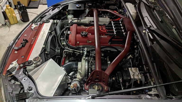
Lokiel's "Gina" (2004 Titanium SE)
Moderators: timk, Stu, zombie, Andrew, The American, Lokiel, -alex, miata, StanTheMan, greenMachine, ManiacLachy, Daffy
- Lokiel
- Forum legend
- Posts: 4126
- Joined: Thu May 28, 2009 2:39 pm
- Vehicle: NB SE
- Location: Brisbania
Re: Lokiel's "Gina" (2004 Titanium SE)
Friday hit a bit of a snag.
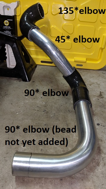
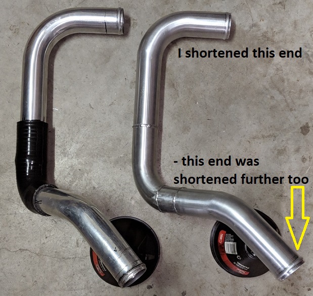
With one extra 2" 90* aluminium pipe, I had enough pipe to make another hotside all-aluminium pipe using the original one (2x aluminium pipes and 1x silicone elbow) as a template:
- the fewer the clamps needed the better!
Gilrow Engineering, who I've used to do my aluminium welding jobs, is only a few shops down from Newman Avenue garage so I figured I'd get them to make the hotside downpipe while the exhaust was being fitted - killing 2 birds with one stone.
I was advised that they were in the process of moving shops but since it was a small job it was do-able.
Unfortunately on Friday it still hadn't been completed and I was offered a discount on the job so took them up on it since I have enough hoses and pipes to fabricate 2.5" hotside plumbing (it'll be tighter but I wont be driving with it so it's not an issue for initial tuning).
Don't worry about dying, worry about not living!
Garage Thread: http://www.mx5cartalk.com/forum/viewtopic.php?f=57&t=76716
- Lokiel
- Forum legend
- Posts: 4126
- Joined: Thu May 28, 2009 2:39 pm
- Vehicle: NB SE
- Location: Brisbania
Re: Lokiel's "Gina" (2004 Titanium SE)
Saturday was a write-off after celebrating our end of year Xmas party on Friday so I only got around to installing the new hotside intercooler plumbing today:
Not sure why they needed that small straight piece at the end of the 45* bend, maybe the silicone hose gave it more bend and they matched it?
This eliminates the need for two extra clamps for that middle silicone coupler but it creates a problem:
WIth the pipe as one piece, manipulating it into place is incredibly difficult and I ended up having to shorten both ends a bit because there was no way I could fit it in the end couplers.
Previously I fitted the pipes in the end couplers then joined them via the middle 90* coupler and it was no problem at all.
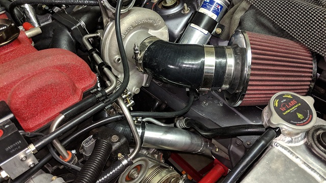
After fitting the intercooler end, I needed to use silicone spray on the turbo-end's coupler to slip it over the pipe and rotate it so that the pipe was aligned correctly.
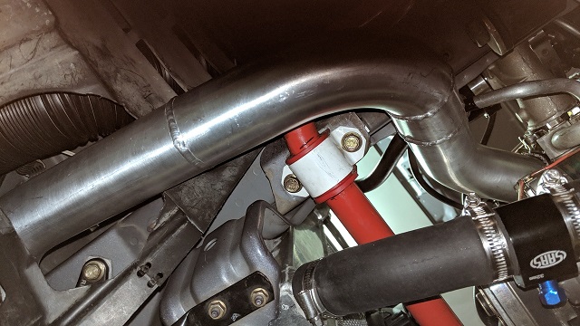
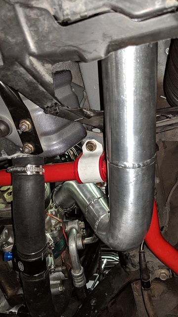
The new pipe fits great, no interference anywhere:
Underside:
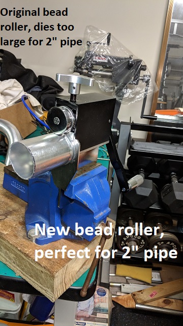
The original bead-roller I bought was too big to bead 2" pipe, the dies were too big to fit the pipe over so I bought another smaller one for the 2" pipe:
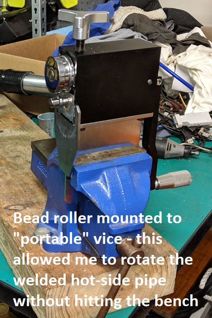
With its long awkward shape, I needed to use my "portable" vice to completely bead-roll the ends of the downpipe, otherwise it hit the bench at some point, preventing the completion of the bead.
If anyone in Brisbane needs aluminium pipe bead-rolled, send me a PM, the bead-rollers will just be gathering dust so are available for use.
Don't worry about dying, worry about not living!
Garage Thread: http://www.mx5cartalk.com/forum/viewtopic.php?f=57&t=76716
- Lokiel
- Forum legend
- Posts: 4126
- Joined: Thu May 28, 2009 2:39 pm
- Vehicle: NB SE
- Location: Brisbania
Re: Lokiel's "Gina" (2004 Titanium SE)
Beavis' latest "at the Dyno" photo prompted me to post my DIY version.
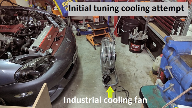
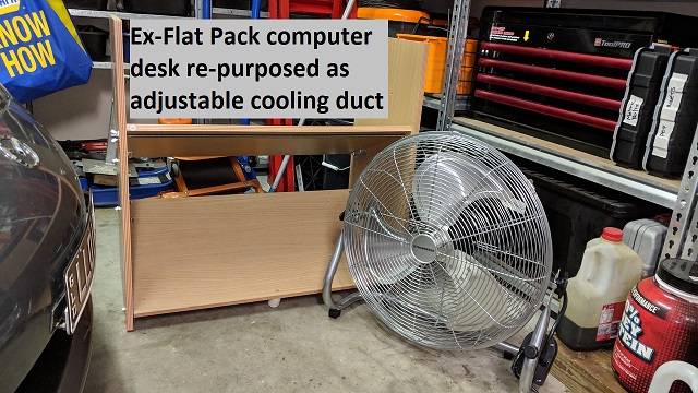
Dyno fan:
When I started tuning this X-mas break I was just using a regular indoor fan pointed at the mouth of Gina but this summer was so hot it did bugger-all and the Spal fan would kick in constantly, not allowing me to Idle-tune until it had stopped. The fan was only off about 20% of the time!
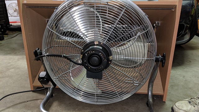
I bought a Bunnings industrial fan, this thing really cranks out some air at its top setting:
Most of this air was simply going over the top or under the car, even with the fan hard-up against "the mouth" of the car.
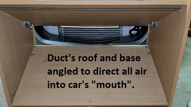
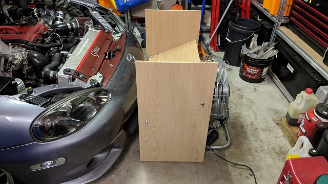
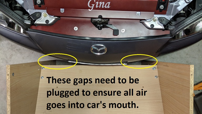
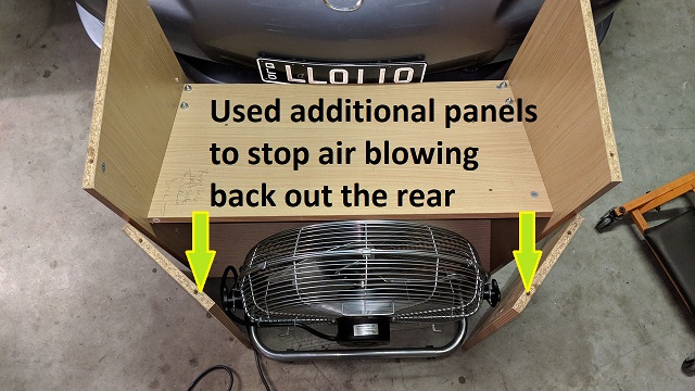
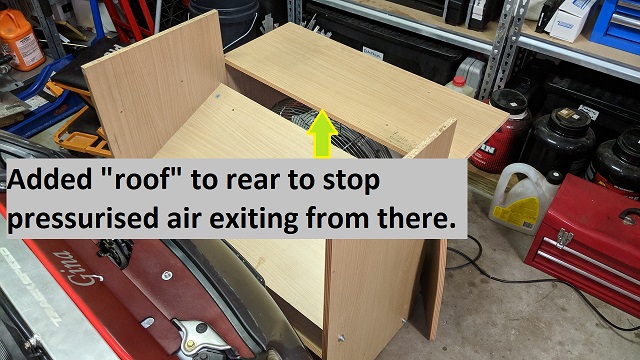
Years ago I'd bought a large flat-pack corner computer desk which I had to disassemble when I got some decent furniture so I re-purposed some of it as a fan duct using some angled aluminium, a threaded rod and some M6x30 bolts and nuts:
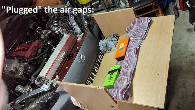
Not much air actually escapes/exits below the front of the "roof" but every bit helps so I plugged the gaps with rags:
Without those two temporary rear vertical panels and the roof on top of them, a lot of air flows back out the duct, they really make a difference.
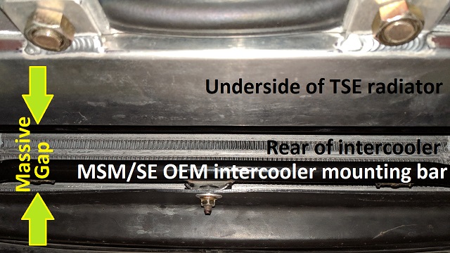
I don't have the undertray on at the moment and noted that a LOT of air was going under the radiator because there's a massive gap there, even with the undertray this gap below the radiator and undertray exists:
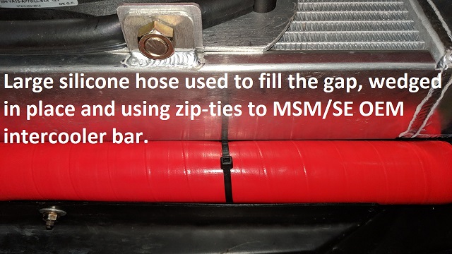
For now I've plugged this gap with a large silicone hose I had lying around:
Now I can actually feel air flowing through the rear of the car's fan when the fan isn't running so I know it's actually working and yes, it does make a difference, now the fan only comes on 60% of the time during a hot day
Most of the "wasted air" now exits to the right and left of the radiator so once I'm done road tuning, I'm going to address ducting the car properly - the external fan duct has shown me where the issues are and what needs to be sealed.
V2.0 may include "misting" for improved performance!
Don't worry about dying, worry about not living!
Garage Thread: http://www.mx5cartalk.com/forum/viewtopic.php?f=57&t=76716
- beavis
- Forum sponsor
- Posts: 1405
- Joined: Mon Feb 02, 2009 12:31 pm
- Vehicle: NB8B - Turbo
- Location: Melbourne
Re: Lokiel's "Gina" (2004 Titanium SE)
Haha. Flawless!
Turbo NB Build Thread | BeavisMotorsport.com | YouTube.com/bbeavis | Cars: NA6, NA8-VVT, NB-Turbo, ND-2L
- Daffy
- Forum legend
- Posts: 1366
- Joined: Tue Apr 28, 2015 3:23 pm
- Vehicle: NB SE
- Location: Southern Gold Coast QLD
Re: Lokiel's "Gina" (2004 Titanium SE)
Brilliant! As the great Darryl Kerrigan said Lokiel.......
You do not have the required permissions to view the files attached to this post.
- Lokiel
- Forum legend
- Posts: 4126
- Joined: Thu May 28, 2009 2:39 pm
- Vehicle: NB SE
- Location: Brisbania
Re: Lokiel's "Gina" (2004 Titanium SE)
I haven't updated my build thread for a while but have been busy doing a few small jobs while procrastinating about how to mount my fan relays, hot-side oil catch can, route my A/C lines and making a new Cold Air Box since my existing one was too big and now oriented wrong for the air filter.
The first thing was to re-make my CNPS harness to make it longer so that I didn't simply have a massive jumble of wires directly behind the engine and to eliminate the capacitors on it since they're a point of failure and few on MT.net believe they're needed anyway.
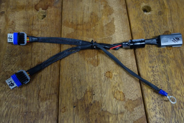
This was one of the original CNPS harnesses, two are needed when using wasted spark ignition (one for coils 1&4, and another for 2&3):
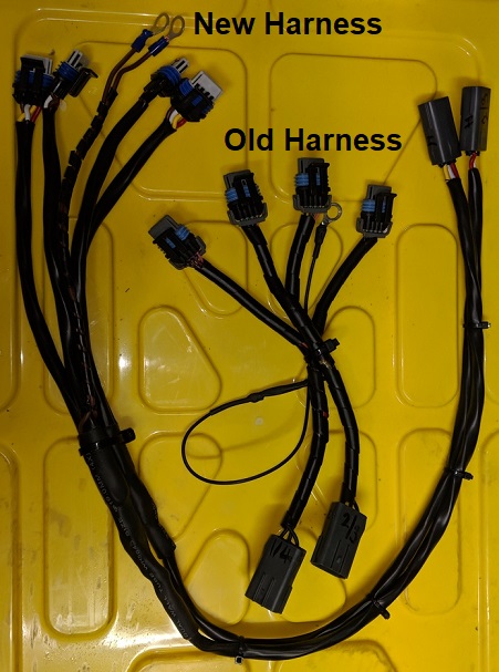
I used 8 amp 5-core trailer cable (one of the cores was removed since only 4 are needed) which is slightly too large for the plugs and pins so they were incredibly tight to fit and extra time and swearing was required to make the harnesses:
The new harness is incredibly robust and allows tidier connection to the OEM harness rather than it all being in a tight mess between the engine and firewall.
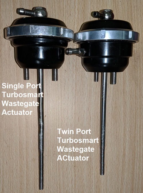
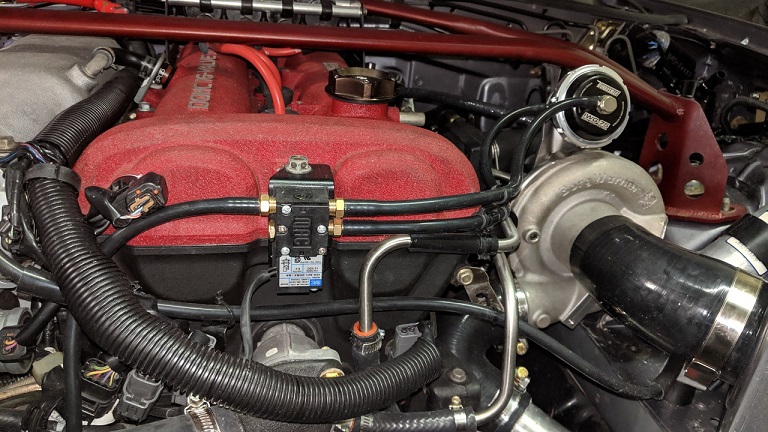
One of the recommended upgrades for EFR turbos, and many other turbos, is the use of a twin-port wastegate actuator since it makes boost control easier and smoother. You also need a 4-port MAC valve since there are now two ports on the wastegate actuator. I was going to do it eventually so figured why not do it straight away and not waste any time re-tuning boost after switching from a single-port to twin-port actuator.
Most MAC valves are blue which doesn't fit my engine bay's coloutr scheme so I re-sprayed it black - much nicer!
The default Turbosmart wastegate actuator comes with two 7psi springs, an inner one and outer one.
Andrew/Savington from TSE recommended initially removing one of the springs, ludicrous boost can come later if needed, so I followed his advice.
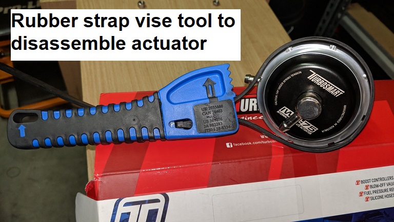
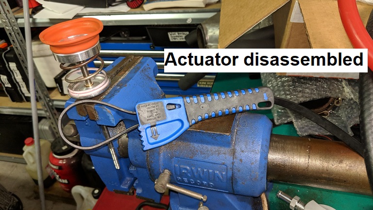
The Turbosmart wastegate actuators can be disassembled with a custom spanner on the locking ring, similar to those used on coilovers but I didn't have one and didn't want to marr/destroy the locking ring. Luckily my rubber-strap vise hand-tool handled the job easily:
Don't worry about dying, worry about not living!
Garage Thread: http://www.mx5cartalk.com/forum/viewtopic.php?f=57&t=76716
- Lokiel
- Forum legend
- Posts: 4126
- Joined: Thu May 28, 2009 2:39 pm
- Vehicle: NB SE
- Location: Brisbania
Re: Lokiel's "Gina" (2004 Titanium SE)
I've been procrastinating about how to mount my fan relays, hot-side oil catch can, route my A/C lines and making a new Cold Air Box since my existing one was too big and now oriented wrong for the air filter.
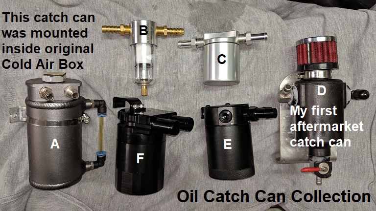
I added a few new oil catch cans to my "collection" in the hopes that I could find a good spot to mount one on the hot-side of the engine bay - I don't simply want to use an air filter on that side in case it leaks with oil when the rocker cover is under positive pressure:
There just doesn't seem to be a decent place to mount the catch can that allows it to be inspected/emptied easily so this Easter weekend I finally got off my butt and started the new Cold Air Box, maybe I could mount the catch can to it?
This was the original Cold Air Box I made for my low-mount turbo:
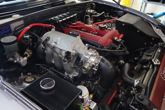
The Cold Air Box was huge and housed my fan relays and oil catch can inside the box.
With the high-mount turbo and A/C cannister re-located just in front of the front strut brace, the new Cold Air Box would have to be much smaller.
Here's the space I had to work with:
The wall of my original Cold Air Box was 3mm aluminium but this time I used 2mm aluminium since it's strong enough and easier to bend in my brake (3mm is really too thick for it).
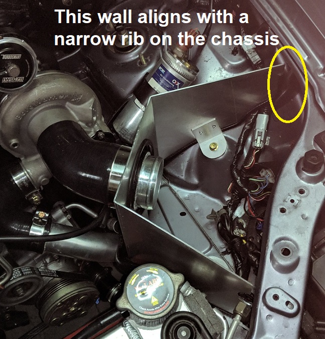
I used a 90* aluminium bracket to mount it to an OEM M6 mount-point.
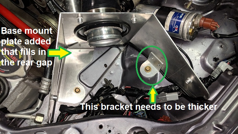
This bracket is too thin since it flexes, allowing the wall to move too easily, and will be replaced with a thicker one.
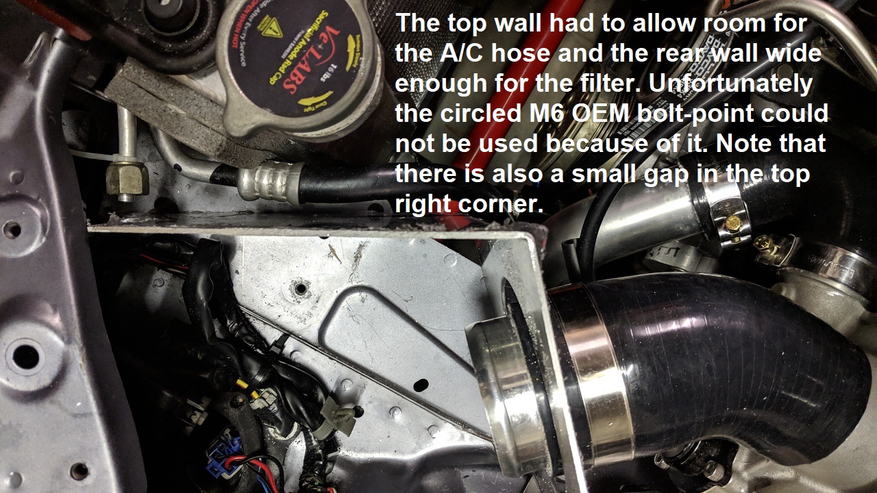
To accomodate the air filter, the Cold Air Box needs to extend beyond the left of the shelf, leaving a small gap which I filled using a base-plate pop-riveted to the wall of the Cold Air Box:
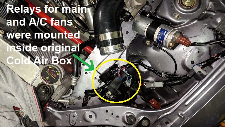
Unfortunately not all three of the fan relays are going to fit:
Now that I'm using a single TSE fan, I can get rid of the unused relay so that's some good incentive to get rid of it.
The roof was interesting because the left side of the Cold Air Box slopes downward:
The roof is mounted to the top of the wall using 4x M6 bolts and rivnuts:
Installed:
I plan to annodise the box black to match my coolant overflow tank but will wait until the A/C lines have been sorted because I suspect an exit slot will be needed at the right rear of the box.
Now that I've made the Cold Air Box, I can see that I can't mount an Oil Catch Can to/in it.
There's an unused bolt in the rear hot-side corner of the engine bay that I may be able use, mounting an L-bracket to it and the catch-can to that?
To inspect/empty it will require unbolting the bracket though
I added a few new oil catch cans to my "collection" in the hopes that I could find a good spot to mount one on the hot-side of the engine bay - I don't simply want to use an air filter on that side in case it leaks with oil when the rocker cover is under positive pressure:
There just doesn't seem to be a decent place to mount the catch can that allows it to be inspected/emptied easily so this Easter weekend I finally got off my butt and started the new Cold Air Box, maybe I could mount the catch can to it?
This was the original Cold Air Box I made for my low-mount turbo:
The Cold Air Box was huge and housed my fan relays and oil catch can inside the box.
With the high-mount turbo and A/C cannister re-located just in front of the front strut brace, the new Cold Air Box would have to be much smaller.
Here's the space I had to work with:
The wall of my original Cold Air Box was 3mm aluminium but this time I used 2mm aluminium since it's strong enough and easier to bend in my brake (3mm is really too thick for it).
I used a 90* aluminium bracket to mount it to an OEM M6 mount-point.
This bracket is too thin since it flexes, allowing the wall to move too easily, and will be replaced with a thicker one.
To accomodate the air filter, the Cold Air Box needs to extend beyond the left of the shelf, leaving a small gap which I filled using a base-plate pop-riveted to the wall of the Cold Air Box:
Unfortunately not all three of the fan relays are going to fit:
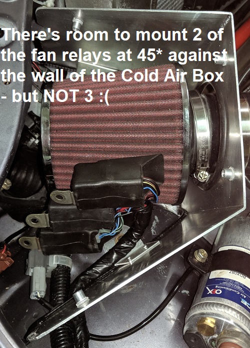
Now that I'm using a single TSE fan, I can get rid of the unused relay so that's some good incentive to get rid of it.
The roof was interesting because the left side of the Cold Air Box slopes downward:
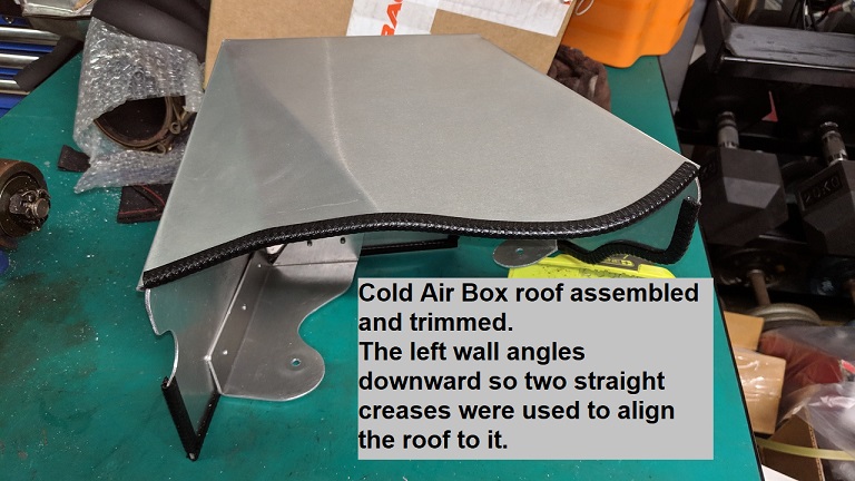
The roof is mounted to the top of the wall using 4x M6 bolts and rivnuts:
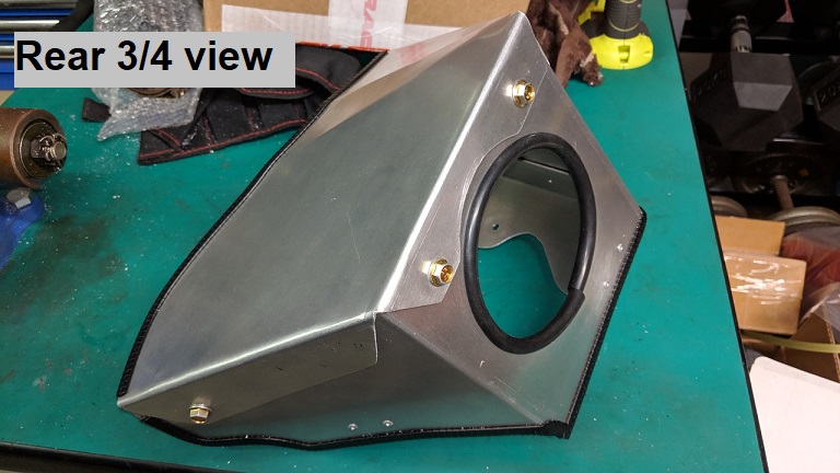
Installed:
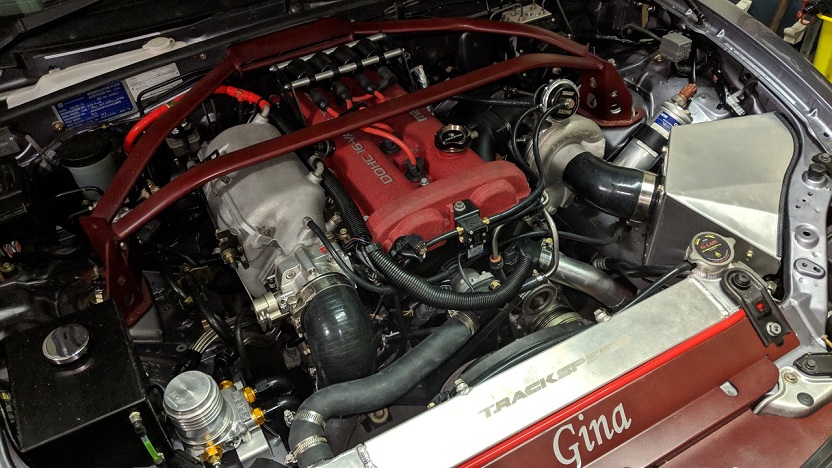
I plan to annodise the box black to match my coolant overflow tank but will wait until the A/C lines have been sorted because I suspect an exit slot will be needed at the right rear of the box.
Now that I've made the Cold Air Box, I can see that I can't mount an Oil Catch Can to/in it.
There's an unused bolt in the rear hot-side corner of the engine bay that I may be able use, mounting an L-bracket to it and the catch-can to that?
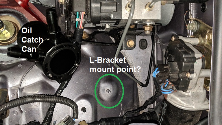
To inspect/empty it will require unbolting the bracket though
Don't worry about dying, worry about not living!
Garage Thread: http://www.mx5cartalk.com/forum/viewtopic.php?f=57&t=76716
- Lokiel
- Forum legend
- Posts: 4126
- Joined: Thu May 28, 2009 2:39 pm
- Vehicle: NB SE
- Location: Brisbania
Re: Lokiel's "Gina" (2004 Titanium SE)
Didn't get as much done today as I hoped since the morning was a write-off.
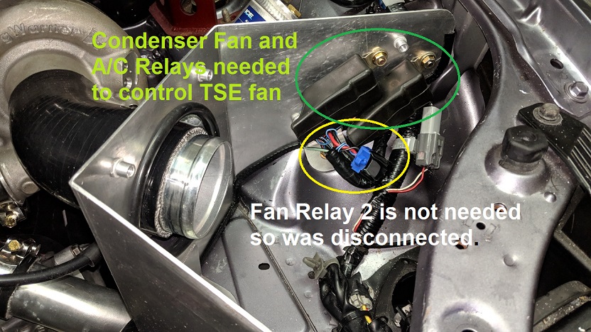
After studying the MSM Wiring diagrams and Cooling Fan documentation, I determined what the front 3 relays were for:
1. Fan Relay 2 (blue plug) - when energised, directs voltage to the MSM fan 1&2 low-speed motors
2. Condenser Fan Relay (clear plug) - when energised, directs voltage to the condenser fan, which on the MSM is the Fan 2 high-speed motor
3. A/C Relay (black plug) - when energised, directs voltage to the A/C compressor magnetic clutch
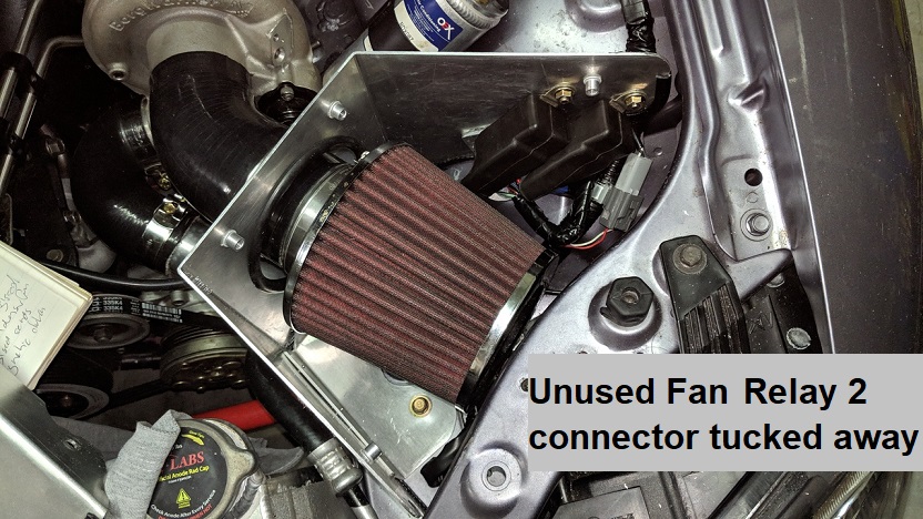
My single-speed TSE fan is wired to the harness' Fan 2 high speed motor wiring so Fan Relay 2 is un-needed so I removed it, taped over the plug and tucked it out of the way.
I also replaced the flimsy 90* aluminium bracket with one that was 3mm thick, making the wall much stronger.
I can now put my hands on the two rear corners of the Cold Air Box and lean right into the engine bay so I'm happy with its strength.
Don't worry about dying, worry about not living!
Garage Thread: http://www.mx5cartalk.com/forum/viewtopic.php?f=57&t=76716
- Roadrunner
- coyotes after you
- Posts: 1111
- Joined: Tue Nov 06, 2012 9:02 pm
- Vehicle: NB SE
- Location: Newcastle
Re: Lokiel's "Gina" (2004 Titanium SE)
Great work on the airbox.
Whats your plans with routing the catch can (Mishimoto Compact Can?). Will you keep the PCV valve or run both cover outlets to the can? If you are retaining the PCV (which MiataTurbo recommends for street dríven cars) are you worried about blowing boost past it and/or sucking oil on track off throttle?
MeepMeep
- Lokiel
- Forum legend
- Posts: 4126
- Joined: Thu May 28, 2009 2:39 pm
- Vehicle: NB SE
- Location: Brisbania
Re: Lokiel's "Gina" (2004 Titanium SE)
Oil catch can "E" above is a 3-port version of the Mishimoto Compact Can, output port in the middle, 2 inputs either side of it to allow users to select one based on their routing.
I've spent a lot of time reading the MT.net oil catch can threads.
I plan on running a hose from the hot-side rocker cover barb to the catch can, to an air filter (or back into the air intake).
For the coldside, I want to install another can between the PCV valve and manifold to catch oil/blow-by.
Where/how I can mount it I have NO idea, even after purchasing a bunch of different sized cans.
The problem is that most are round cylinders so tend to be too deep - I need to keep looking
Unfortunately Dann's catch can wont work for me because the turbo is in the way
Don't worry about dying, worry about not living!
Garage Thread: http://www.mx5cartalk.com/forum/viewtopic.php?f=57&t=76716
- greenMachine
- Forum Guru
- Posts: 4053
- Joined: Thu Apr 24, 2003 11:00 am
- Vehicle: NB SE
- Location: Sports car paradise - Canberra
- Contact:
Re: Lokiel's "Gina" (2004 Titanium SE)
I would be running both lines to one catchtank. ATM I still have the stock PCV setup, but that will go and be replaced, probably by a hose to a Y join in the hotside vent hose. You are using at least 10AN hose, and have done the 'tiny hole' mod? my VTA is inside the cold air box, out of sight, and probably even legal .
Space is a serious problem, isn't it? Given my time again, I would be looking at the space in front of the LHS front wheel, under the guard. Longer hose run, but with a drain hose with a tap/plug on the end it seems workable. I would probably DIY the tank, either repurposing some other container, or build from scratch.
I never met a horsepower I didn't like (thanks bwob)
Build thread
NB SE - gone to the dark side (and loving it )
Build thread
NB SE - gone to the dark side (and loving it )
- Lokiel
- Forum legend
- Posts: 4126
- Joined: Thu May 28, 2009 2:39 pm
- Vehicle: NB SE
- Location: Brisbania
Re: Lokiel's "Gina" (2004 Titanium SE)
Finalised the hot-side oil catch can this weekend.
I decided to mount it on the OEM 6mm bolt noted earlier:
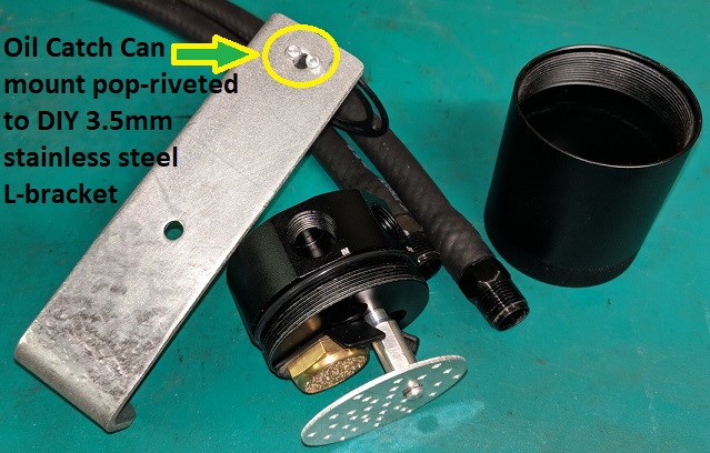
I bought a short length of 40mm wide x 3.5mm deep stainless steel reinforcing plate with pre-drilled 6mm holes - I figured it would save me from drilling at least one hole. This will be stronger than the equivalent aluminium bracket and less likely to crack with fatigue where I need to bend it.
To ensure that the bracket would be vertical, I added a ~95* bend to the end since the base angles downward to the rear of the engine bay.
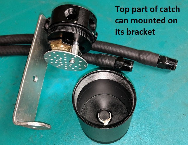
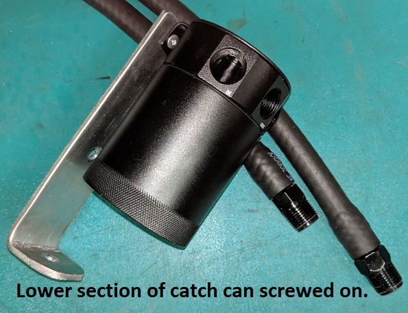
I cut it to length and pop-riveted the oil catch can's bracket to it. Unfortunately this was almost exactly where an existing 6mm hole in my DIY bracket was, the rivets straddle the hole. It holds well enough and in hindsight I could have made the bracket 5-10mm taller which would have avoided this:
The 3/8" hoses were incredibly hard to fit on the 3/8" NPT barbs, even after using a heat gun on the rubber ends. I ended up using silicone spray and, after producing a decent bloody cut in my left index finger from the barb, used a vice to hold the barb instead. No need to use hose clamps on these barbs, I'll have to cut the rubber to get them off if I need to!
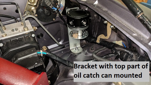
I sandwiched a 3mm rubber pad between the chassis and the bracket and mounted it with a M6 nylock nut:
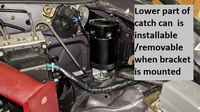
The lower part of the catch can can be installed/removed by screwing/unscrewing it, tilting it slightly to get it out - not as easy as I'd like but given space limitations, something I'll have to live with:
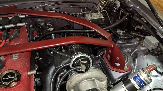
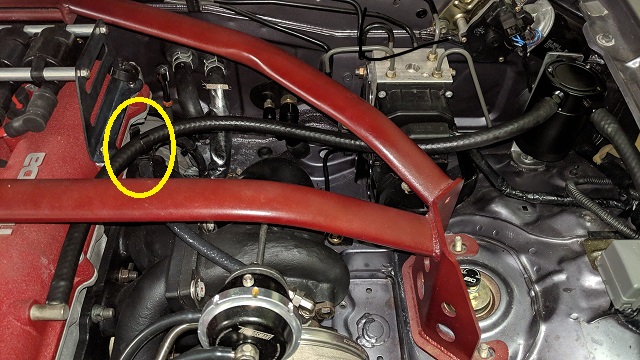
After screwing in the barbs and routing+fitting the hoses (for now, hose runs into Cold Air Box under the filter where it simply vents), I used an OEM hose separator, see yellow circle in 2nd photo below to ensure that the hose and turbo 4-AN hose don't rub:
I plan on sheathing the hose to the rocker cover with SpeedHut 10-AN heat sheath for added heat protection.
The bracket it very sturdy and the hoses help dampen forward and rearward movement of the bracket so I'm happy with how it turned out (though I may make it another 10mm taller if it proves to be too much hassle to remove when emptying it.
Don't worry about dying, worry about not living!
Garage Thread: http://www.mx5cartalk.com/forum/viewtopic.php?f=57&t=76716
- Lokiel
- Forum legend
- Posts: 4126
- Joined: Thu May 28, 2009 2:39 pm
- Vehicle: NB SE
- Location: Brisbania
Re: Lokiel's "Gina" (2004 Titanium SE)
greenMachine wrote:I would be running both lines to one catchtank. ATM I still have the stock PCV setup, but that will go and be replaced, probably by a hose to a Y join in the hotside vent hose. You are using at least 10AN hose, and have done the 'tiny hole' mod? my VTA is inside the cold air box, out of sight, and probably even legal .
:
I'm still using the stock barbs which are 3/8" I believe (MT.net recommends enlarging them to 10AN).
My outlet hose, like yours, simply runs into the cold air box and under the filter- I "may" add a barb to the turbo's silicone elbow intake and join it there.
I don't think that a single catch-can should be used on a street+track car.
When there is vacuum, eg. when idling, blow-by air is sucked from the rocker cover out the coldside (that's why the inside of your intake manifold gets covered in black crap).
When there is positive pressure, eg, when boosting, the coldside's PCV valve closes and blow-by air is forced out the hotside, which is why it needs a catch can and not a simple air filter.
If you have a single catch can for both ports that vents to atmosphere, it will only get rid of the blow-by air under boost which is OK for a track car but not a street car which shouldn't be spending much time in boost.
Don't worry about dying, worry about not living!
Garage Thread: http://www.mx5cartalk.com/forum/viewtopic.php?f=57&t=76716
-
- Speed Racer
- Posts: 2189
- Joined: Fri Nov 29, 2013 8:51 am
- Vehicle: ND - RF
- Location: Sydney
Re: Lokiel's "Gina" (2004 Titanium SE)
Lokiel wrote:If you have a single catch can for both ports that vents to atmosphere, it will only get rid of the blow-by air under boost which is OK for a track car but not a street car which shouldn't be spending much time in boost.
However if you have both sides of the crankcase ducted to a single catch can venting to the intake tract after the filter but before the turbo it will only ever see vacuum while the engine is running thus solving the problem, it's what I have done.
NB: if you are still using a MAF then it needs to be before the MAF to prevent issues......
EDIT: in a NA application, so long as the return is located between the filter and the throttle body you will get the same result.
"A Convertible has a top you can put down when the weather's nice...... A Roadster has a top you can put up when the weather's bad."
- greenMachine
- Forum Guru
- Posts: 4053
- Joined: Thu Apr 24, 2003 11:00 am
- Vehicle: NB SE
- Location: Sports car paradise - Canberra
- Contact:
Re: Lokiel's "Gina" (2004 Titanium SE)
Lokiel wrote:greenMachine wrote:I would be running both lines to one catchtank. ATM I still have the stock PCV setup, but that will go and be replaced, probably by a hose to a Y join in the hotside vent hose. You are using at least 10AN hose, and have done the 'tiny hole' mod? my VTA is inside the cold air box, out of sight, and probably even legal .
:
I'm still using the stock barbs which are 3/8" I believe (MT.net recommends enlarging them to 10AN).
My outlet hose, like yours, simply runs into the cold air box and under the filter- I "may" add a barb to the turbo's silicone elbow intake and join it there.
I think that the dual stage filtration (VTA filter, intake air filter) of the excess catchcan gasses is a good thing. It will trap at least some of the particulate matter and reduce the crap going through the turbo, and through your combustion chamber.
I don't think that a single catch-can should be used on a street+track car.
When there is vacuum, eg. when idling, blow-by air is sucked from the rocker cover out the coldside (that's why the inside of your intake manifold gets covered in black crap).
When there is positive pressure, eg, when boosting, the coldside's PCV valve closes and blow-by air is forced out the hotside, which is why it needs a catch can and not a simple air filter.
If you have a single catch can for both ports that vents to atmosphere, it will only get rid of the blow-by air under boost which is OK for a track car but not a street car which shouldn't be spending much time in boost.
Venting to a single catchcan (no PCV) will provide an outlet for both cases. Under boost, the excess pressure VTA via the catchcan. At non-boost running (idle etc), by definition the blow-by is pressurising the engine, and that pressure is also VTA via the catchcan. There is no non-return valve in the system, so if needed (and I think it is not needed), the flow can reverse.
When I installed the 10an fitting on my RC, it seemed that the area of the 10AN was noticeably bigger than the stock. That is important, it reduces the velocity of the gasses, thereby reducing the oil vapour and particulates drawn out with the high speed vapour. This is also the reasoning behind the tiny hole mod.
I never met a horsepower I didn't like (thanks bwob)
Build thread
NB SE - gone to the dark side (and loving it )
Build thread
NB SE - gone to the dark side (and loving it )
Who is online
Users browsing this forum: No registered users and 265 guests