Lokiel's "Gina" (2004 Titanium SE)
Moderators: timk, Stu, zombie, Andrew, The American, Lokiel, -alex, miata, StanTheMan, greenMachine, ManiacLachy, Daffy
- Lokiel
- Forum legend
- Posts: 4126
- Joined: Thu May 28, 2009 2:39 pm
- Vehicle: NB SE
- Location: Brisbania
Re: Lokiel's "Gina" (once a 2004 Titanium SE) Recreated AGAIN
Originally posted by Okibi, Thu Mar 22, 2018 10:31 pm
Looks awesome, would love to have a better understanding of electronics.
Originally posted by ManiacLachy, Fri Mar 23, 2018 7:49 am
I am still stupidly impressed by all of this, wow!
I can't wait to get my hands on one.
Looks awesome, would love to have a better understanding of electronics.
Originally posted by ManiacLachy, Fri Mar 23, 2018 7:49 am
I am still stupidly impressed by all of this, wow!
I can't wait to get my hands on one.
Don't worry about dying, worry about not living!
Garage Thread: http://www.mx5cartalk.com/forum/viewtopic.php?f=57&t=76716
- Lokiel
- Forum legend
- Posts: 4126
- Joined: Thu May 28, 2009 2:39 pm
- Vehicle: NB SE
- Location: Brisbania
Re: Lokiel's "Gina" (once a 2004 Titanium SE) Recreated AGAIN
Originally posted by Lokiel, Fri Apr 20, 2018 10:15 am
BUGGER!
My new photo-hosting site, postimages.org, has now been classified as a "pron site" so all photos no lo longer work since many forum sites just truncate the image location to "https://postimages.cc/" or indicate that the site is "barred"!
Looks like I'm going to have to repeat the process of re-hosting the photos
Originally posted by ManiacLachy, Fri Apr 20, 2018 10:21 am
I thought it was just me and my overzealous work firewall. That sucks!
I use Imgur for what it's worth, it's not bad but make sure you set your uploads and albums to private or you'll get the masses commenting on your photos. Externally linked photos will still work no problem.
Originally posted by greenMachine, Fri Apr 20, 2018 10:49 am
I just have to say it - the free sites give great value for money, you get exactly what you pay for.
There, I feel much better now.
Carry on...
Originally posted by takai, Fri Apr 20, 2018 11:23 am
Switch to Imgur or Flickr.
If you have your own hosting then you can use piwigo.
Originally posted by SKYHI, Fri Apr 20, 2018 11:37 am
I was looking over this thread yesterday and wondered what had happened to the photos
Another vote for imgur.
Originally posted by Gladiator, Fri Apr 20, 2018 2:14 pm
That s the sole reason I do all my posts on my iPhone via, (as much as I always complain about it), tapatalk. I can post photos straight from my phone.
Sent from my iPhone using Tapatalk
Originally posted by takai, Fri Apr 20, 2018 3:31 pm
And when tapatalk goes down?
Originally posted by Gladiator, Fri Apr 20, 2018 9:47 pm
That s when I whinge & bitch & complain about how much I hate tapatalk. <IMG src="http://emoji.tapatalk-cdn.com/emoji23.png" /><IMG src="http://emoji.tapatalk-cdn.com/emoji23.png" />
Sent from my iPhone using Tapatalk
BUGGER!
My new photo-hosting site, postimages.org, has now been classified as a "pron site" so all photos no lo longer work since many forum sites just truncate the image location to "https://postimages.cc/" or indicate that the site is "barred"!
Looks like I'm going to have to repeat the process of re-hosting the photos
Originally posted by ManiacLachy, Fri Apr 20, 2018 10:21 am
I thought it was just me and my overzealous work firewall. That sucks!
I use Imgur for what it's worth, it's not bad but make sure you set your uploads and albums to private or you'll get the masses commenting on your photos. Externally linked photos will still work no problem.
Originally posted by greenMachine, Fri Apr 20, 2018 10:49 am
I just have to say it - the free sites give great value for money, you get exactly what you pay for.
There, I feel much better now.
Carry on...
Originally posted by takai, Fri Apr 20, 2018 11:23 am
Switch to Imgur or Flickr.
If you have your own hosting then you can use piwigo.
Originally posted by SKYHI, Fri Apr 20, 2018 11:37 am
I was looking over this thread yesterday and wondered what had happened to the photos
Another vote for imgur.
Originally posted by Gladiator, Fri Apr 20, 2018 2:14 pm
That s the sole reason I do all my posts on my iPhone via, (as much as I always complain about it), tapatalk. I can post photos straight from my phone.
Sent from my iPhone using Tapatalk
Originally posted by takai, Fri Apr 20, 2018 3:31 pm
Gladiator wrote:That s the sole reason I do all my posts on my iPhone via, (as much as I always complain about it), tapatalk. I can post photos straight from my phone.
Sent from my iPhone using Tapatalk
And when tapatalk goes down?
Originally posted by Gladiator, Fri Apr 20, 2018 9:47 pm
That s when I whinge & bitch & complain about how much I hate tapatalk. <IMG src="http://emoji.tapatalk-cdn.com/emoji23.png" /><IMG src="http://emoji.tapatalk-cdn.com/emoji23.png" />
Sent from my iPhone using Tapatalk
Don't worry about dying, worry about not living!
Garage Thread: http://www.mx5cartalk.com/forum/viewtopic.php?f=57&t=76716
- Lokiel
- Forum legend
- Posts: 4126
- Joined: Thu May 28, 2009 2:39 pm
- Vehicle: NB SE
- Location: Brisbania
Re: Lokiel's "Gina" (once a 2004 Titanium SE) Recreated AGAIN
WooHoo - finally recreated all posts (for the 2nd time)!
New updates coming later this week.
Don't worry about dying, worry about not living!
Garage Thread: http://www.mx5cartalk.com/forum/viewtopic.php?f=57&t=76716
- ManiacLachy
- Forum Guru
- Posts: 3266
- Joined: Mon Jan 13, 2014 2:35 pm
- Vehicle: NB SE
- Location: Brisbane
Re: Lokiel's "Gina" (once a 2004 Titanium SE) Recreated AGAIN
And a useful resource has been returned to us! Thanks Lokiel. Let's hope this is the last time.
- SKYHI
- Racing Driver
- Posts: 1355
- Joined: Sun Apr 01, 2007 8:08 am
- Vehicle: NB SE
- Location: Brisbane
Re: Lokiel's "Gina" (once a 2004 Titanium SE) Recreated AGAIN
Great to see this thread resurrected again. I keep reading through it trying to get my head around the Arduino stuff, but most of it goes straight over my head.
Just starting to look into options to get the most out of my MS3Pro PnP ecu and come up with a data logging and engine monitoring system for my SE track car.. I think we need to talk soon
- Lokiel
- Forum legend
- Posts: 4126
- Joined: Thu May 28, 2009 2:39 pm
- Vehicle: NB SE
- Location: Brisbania
Re: Lokiel's "Gina" (2004 Titanium SE)
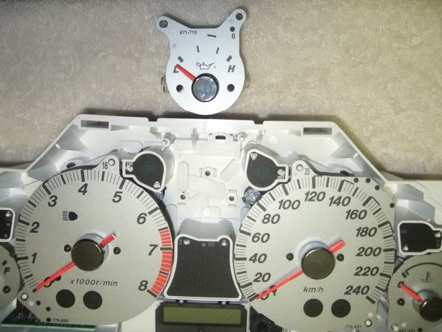
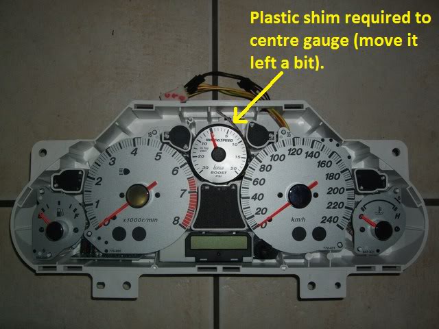
"Yonks ago" I fitted a SpeedHut boost gauge into the OEM oil gauge's location - I call this "The '95MSM Boost Gauge Mod" in honour of the mazda-speed.com forum member who pioneered it.
Basically you remove your OEM "dummy oil pressure" gauge:
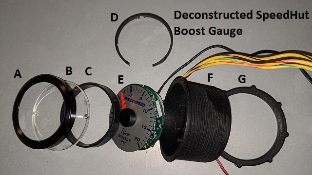
Pull the SpeedHut Gauge apart (it just unscrews by hand):
A - Gauge cover locker (screws on)
B - Gauge lens
C - Spacer between lens and fascia (fits inside the cup and holds gauge fascia in place)
D - Spacer between fascia and PCB
E - Gauge Fascia and PCB (D fits between these)
F - Gauge housing/cup
G - Housing cup locking ring (screws on to secure gauge to mounting panel)
Throw away A,B,C and G.
Cut the panel lip off F and file the crap out of its sides to get it to fit in place because it's REALLY tight:
* I drilled 2 holes in the base corresponding to 2 of the OEM screw holes and used a zip-tie to hold it in place using two holes.
* the gauge fascia+spacer+PCB is just pushed into the cup and the OEM fascia's centre gauge round moulding holds it in place.
That works, but "We can do BETTER!" - if we have a 3D printer.
My Prusa i3 Mk3 3D printer kit arrived a few weeks ago and I assembled it and got it running so I may as well "get onto it":
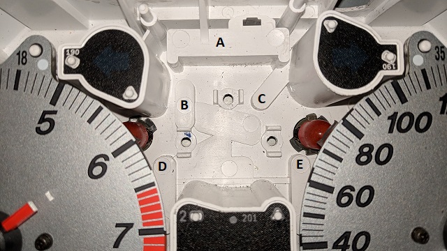
So here's the space I had to work with:
A - Tall OEM moulding
B,C,D.E - Lower OEM moldings (same height)
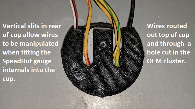
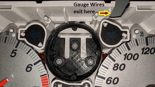
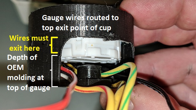
Wiring needs to be routed over "A" and out the top of the cluster, it can't go under either of the larger gauges otherwise it will create a shadow on the gauge.
Unfortunately the wires on the SpeedHut gauge are on the bottom
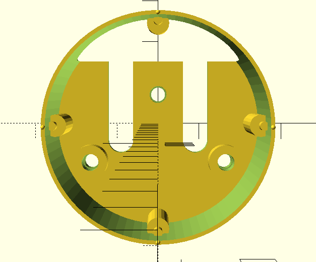
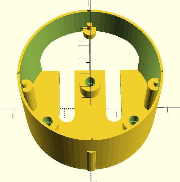
I use OpenSCAD as my 3D design tool (as a programmer by trade, it's the most natural choice since it's much like writing code) and Cura as my slicing program.
I used draft settings when 3D-printing in the pictures below since it takes over 2 hours to print the cup and I keep tweaking it.
Cup fitted into position (held by 3mm screws into nylon nuts):
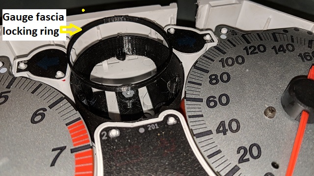
I made my own shorter fascia locking ring because the gauge internals need to be held in the cup for the final install:
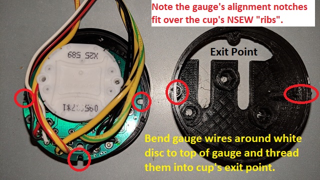
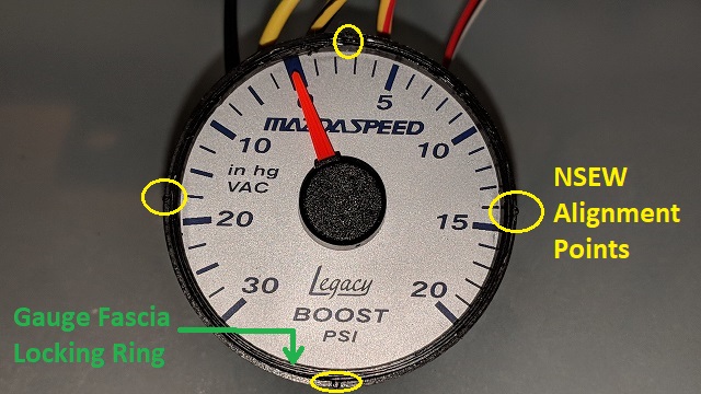
I added the NSEW gauge alignment points to make it easier to insert the PCB into the cup and align the gauge fascia correctly.
Top of gauge showing wiring:
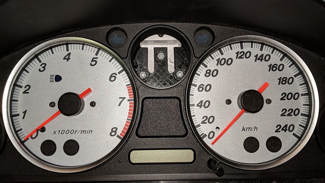
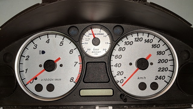
And finally:
- looks just like it did before I went through all that effort
- but it's better and I can easily reproduce more of them!
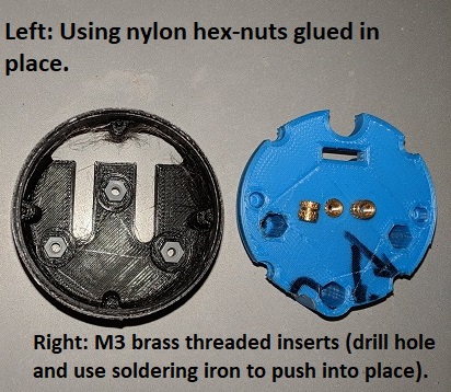
Gluing the nylon nuts was a messy business and the next version will make use of M3 Brass threaded inserts:
- they hold incredibly well and take very little effort to push into place with a soldering iron (the hole must be slightly smaller than the nut).
- the CAD drawings above actually show these being used rather than the hexagonal nylon nuts.
When I'm happy with the final version I'll put a "shout-out" if anyone wants one (S&H +$1 for materials) since I know that some people aren't too keen to "destroy" a SpeedHut boost gauge to fit it where it naturally belongs - dead centre of the instrument cluster!
Don't worry about dying, worry about not living!
Garage Thread: http://www.mx5cartalk.com/forum/viewtopic.php?f=57&t=76716
- KevGoat
- Speed Racer
- Posts: 3940
- Joined: Sun Jun 17, 2012 8:48 pm
- Vehicle: NB SE
- Location: Down South, Adelaide, SA
Re: Lokiel's "Gina" (2004 Titanium SE)
That would make the whole saga a lot easier than the current method, especially with the case fixed to the cluster and the ring holding the gauge in place better - it was quite awkward keeping it all lined up while putting everything back together.
Sent from my SM-G930F using Tapatalk
- Roadrunner
- coyotes after you
- Posts: 1111
- Joined: Tue Nov 06, 2012 9:02 pm
- Vehicle: NB SE
- Location: Newcastle
Re: Lokiel's "Gina" (2004 Titanium SE)
That is awesome! I would have definitely grabbed one of these if they were available when I did mine.Hey if I ever re-do it, I'll probably grab one anyway as my gauge cup is beyond egg shell thin and will probably break if I touch it again.
Put these out for sale and it'll revolutionise the boost gauge mod. I reckon so many more people will do this mod if it was this easy.
Well done and I wish I had the knowledge to design stuff for 3D printing. So many uses!
Oh and bonus of having nylon nuts or threaded inserts in the cup itself, means you can utilise the OIL circuit screw to have a low oil warning light, rather than having to tighten a nut and bolt through the hole.
MeepMeep
- greenMachine
- Forum Guru
- Posts: 4053
- Joined: Thu Apr 24, 2003 11:00 am
- Vehicle: NB SE
- Location: Sports car paradise - Canberra
- Contact:
Re: Lokiel's "Gina" (2004 Titanium SE)
Yes, great work!
I have a set of Speedhut gauges, yet to be installed. Not sure about a boost gauge in that (or any) location though. Oil pressure using a 'proper gauge' ... now that might be something I'd look at ( ). I wonder if they are all the same structure inside, only the mechanism differs?
I have water and oil temp, and oil pressure gauges from Speedhut, purchased for the old GM (need new faces if going in the cluster). Replacing the oil pressure and water temp stockers would be my main interest, I have a couple of spare clusters, I might pull one apart and compare the two small gauge mounts. In fact, I might even start thinking about moving the fuel gauge out and putting all three in the cluster
@SKIHIGH, (and not wishing to highjack this thread), I am in the process of planning a warning light panel to sit under shift lights, removable for the street, for water temp and pressure, oil temp and pressure.
I never met a horsepower I didn't like (thanks bwob)
Build thread
NB SE - gone to the dark side (and loving it )
Build thread
NB SE - gone to the dark side (and loving it )
- Lokiel
- Forum legend
- Posts: 4126
- Joined: Thu May 28, 2009 2:39 pm
- Vehicle: NB SE
- Location: Brisbania
Re: Lokiel's "Gina" (2004 Titanium SE)
Roadrunner wrote::
Oh and bonus of having nylon nuts or threaded inserts in the cup itself, means you can utilise the OIL circuit screw to have a low oil warning light, rather than having to tighten a nut and bolt through the hole.
For my custom OLED gauges and PCB signal box, I steal 12V power, ground and the fuel signal from those screw points on the fuel gauge.
greenMachine wrote:Yes, great work!
I have a set of Speedhut gauges, yet to be installed. Not sure about a boost gauge in that (or any) location though. Oil pressure using a 'proper gauge' ... now that might be something I'd look at ( ). I wonder if they are all the same structure inside, only the mechanism differs?
I have water and oil temp, and oil pressure gauges from Speedhut, purchased for the old GM (need new faces if going in the cluster). Replacing the oil pressure and water temp stockers would be my main interest, I have a couple of spare clusters, I might pull one apart and compare the two small gauge mounts. In fact, I might even start thinking about moving the fuel gauge out and putting all three in the cluster
@SKIHIGH, (and not wishing to highjack this thread), I am in the process of planning a warning light panel to sit under shift lights, removable for the street, for water temp and pressure, oil temp and pressure.
I believe that all SpeedHut gauges are assembled in this manner, it's only the printing and PCB that changes - this makes manufacturing costs/hassles cheaper/easier.
All I need do is flip the bottom 3 screw points 180* in the CAD model for the left and right gauges - there's much more room on the left and right gauges too so the cup wall can be made much thicker - the centre one is a very tight fit so the walls are only 1.8mm thick.
Don't worry about dying, worry about not living!
Garage Thread: http://www.mx5cartalk.com/forum/viewtopic.php?f=57&t=76716
-
- Speed Racer
- Posts: 7468
- Joined: Fri Feb 11, 2011 12:49 pm
- Vehicle: NA6
- Location: Purga, QLD
Re: Lokiel's "Gina" (2004 Titanium SE)
As discussed yesterday http://www.loctite.com.au/light-cure-adhesive-4063.htm
- Roadrunner
- coyotes after you
- Posts: 1111
- Joined: Tue Nov 06, 2012 9:02 pm
- Vehicle: NB SE
- Location: Newcastle
Re: Lokiel's "Gina" (2004 Titanium SE)
Green Machine, definitely put the water gauge in the factory gauge spot. It fits perfect and you don’t have to be a mad scientist to fit it. Minimal cutting required and a built in warning light if you went that option.
MeepMeep
- greenMachine
- Forum Guru
- Posts: 4053
- Joined: Thu Apr 24, 2003 11:00 am
- Vehicle: NB SE
- Location: Sports car paradise - Canberra
- Contact:
Change of plans ...
RR, thanks for that feedback. I think I will go down that track, including relocation of the fuel gauge. No warning light on my coolant temp though, but see ...
Updating, I have just ordered this Ecliptic shift light with warning lights. That means it will be a permanent installation, not removable as originally planned.
greenMachine wrote:@SKIHIGH, (and not wishing to highjack this thread), I am in the process of planning a warning light panel to sit under shift lights, removable for the street, for water temp and pressure, oil temp and pressure.
Updating, I have just ordered this Ecliptic shift light with warning lights. That means it will be a permanent installation, not removable as originally planned.
I never met a horsepower I didn't like (thanks bwob)
Build thread
NB SE - gone to the dark side (and loving it )
Build thread
NB SE - gone to the dark side (and loving it )
- Lokiel
- Forum legend
- Posts: 4126
- Joined: Thu May 28, 2009 2:39 pm
- Vehicle: NB SE
- Location: Brisbania
Re: Lokiel's "Gina" (2004 Titanium SE)
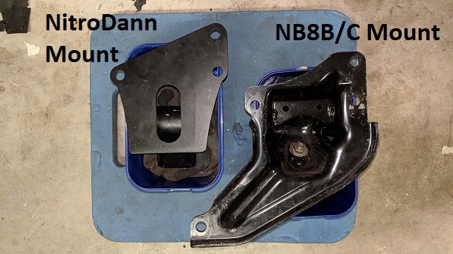
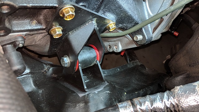
I've FINALLY gotten around to installing the EFR6258 TSE manifold and started by removing NitroDann's manifold, the Cold Air Box and taking the opportunity to install NitroDann's engine mount.
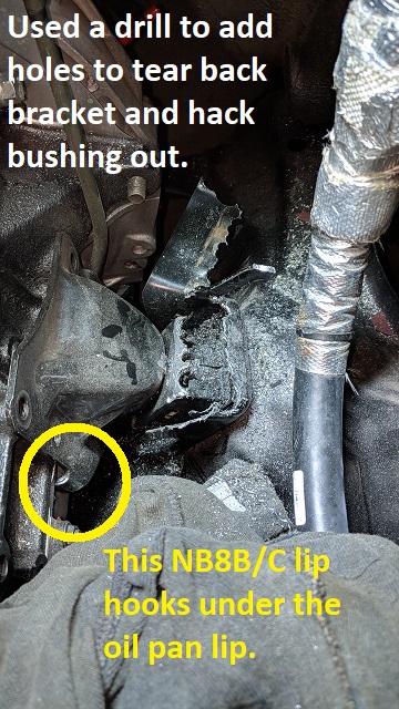
Getting the OEM engine mount was a real bitch and I had to resort to destroying the damn thing with a drill to get it out:
Installing NitroDann's mount in was dead-easy:
Here's the rear face of the two brackets so that you can see why the OEM NNB8C bracket is so difficult to get out:
You can see how bulky the lower arm is on the OEM mount and that you need a lot of clearance to manoeuvre it.
I suspect that you're supposed to be able to pull the mount back a little, rotate the bracket clockwise, pivot it and pull it out in an upward motion.
If the bushing had collapsed, which is when you typically replace it, there may have been enough room to do this.
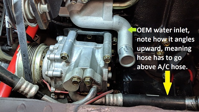
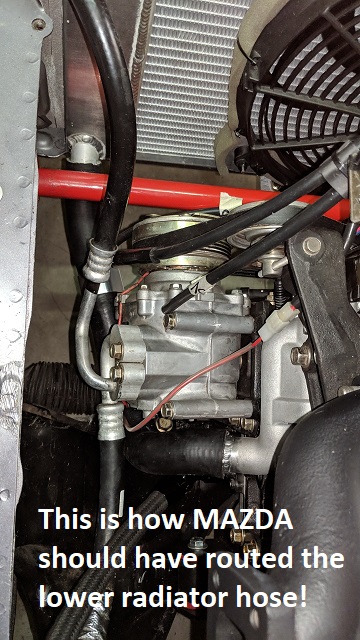
The next job to do while the turbo and exhaust manifold were out was to fix the crappy lower radiator hose routing.
With the convoluted OEM lower radiator hose routing, the hotside intercooler plumbing and radiator hose are competing for the same very limited space.
I've looked into this a lot and thought that the hose could simply run diagonally down behind the A/C compressor and straight to the radiator barb.
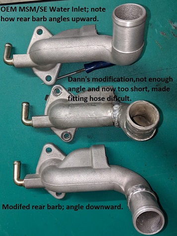
When Dann installed my low-mount exhaust manifold, he needed to modify the water inlet (aka mixing manifold) but essentially kept the same OEM route.
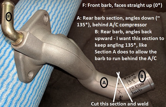
I figured that the MSM/SE water inlet's rear barb could be modified so that the barb continued straight down:
This requires two angled cuts and a single re-weld.
I got Gilrow Engineering in Woolloongabba to make this mod to a new MSM/SE water inlet during the week - I pass them on the way to work and they've done a few other jobs for me too in the past (IAT barb on Fab9 intercooler, master brake cylinder brace on 3-Point front strut brace).
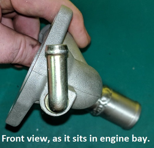
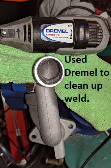
I smoothed the inside with a Dremel to eliminate internal ridges:
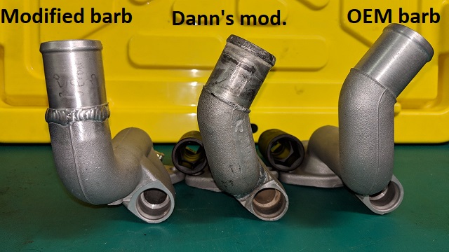
Here's how the 3 versions look next to each other:
Don't worry about dying, worry about not living!
Garage Thread: http://www.mx5cartalk.com/forum/viewtopic.php?f=57&t=76716
- Lokiel
- Forum legend
- Posts: 4126
- Joined: Thu May 28, 2009 2:39 pm
- Vehicle: NB SE
- Location: Brisbania
Re: Lokiel's "Gina" (2004 Titanium SE)
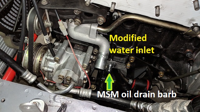
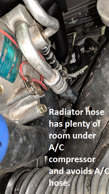
Mounted:
- plenty of clearance behind A/C compressor.
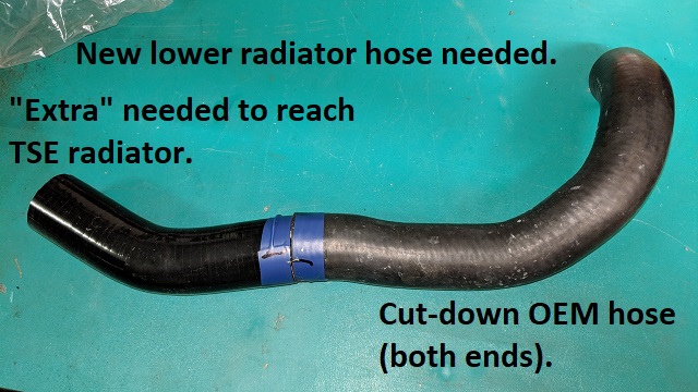
This morning I fashioned the hose I needed from the OEM hose and another piece:
- the blue tape has alignment marks on it.
I ran around to Repco, SuperCheap and Autobarn to see if I could find anything close
- if you ever need a hose, make Repco your first option, they let me look through the stock in the rear and they have 2 walls with hoses hanging from floor to ceiling.
Unfortunately nothing was even close.
I asked about hose joiners and they didn't have any
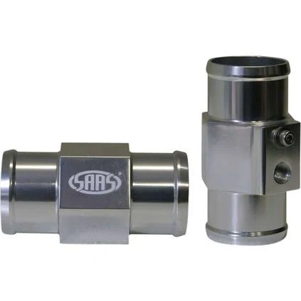
When I got home I remembered that timk once brought around a SAAS upper radiator hose adapter that has a fitting for a sensor in it and needed to tap it for a different sized fitting (SAAS WAT gauge fitting are 1/8" NPT).
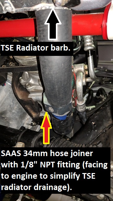
Google showed that my local SuperCheap store had a 34mm one in stock which was close enough to the 32mm ID of the lower radiator hose so I went back and bought it.
The shorter hose was cut a little to accomodate the SAAS adapter:
I plan to add a blanking barb to the l/8" NPT fitting and use it to drain the TSE radiator when needed - the TSE radiator doesn't come with a drain plug so the only way to drain it is to remove the lower radiator hose and coolant sprays everywhere initially until the hose is off.
Tip: If you have a TSE radiator, wrap a towel around the hose when you pull it off to stop it spraying everywhere.
Now I need to find decent worm clamps!
Don't worry about dying, worry about not living!
Garage Thread: http://www.mx5cartalk.com/forum/viewtopic.php?f=57&t=76716
Who is online
Users browsing this forum: No registered users and 23 guests