Originally posted by Lokiel, Sun Feb 09, 2014 12:03 am[
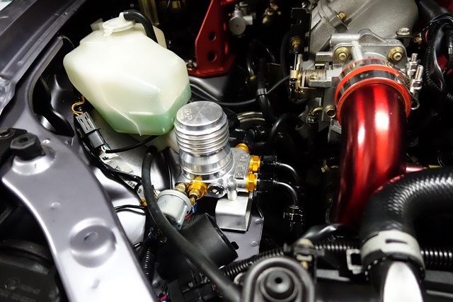
I finally got around to mounting the EFR6258 EBC today and did some wiring re-routing.
The EFR6258's EBC normally mounts to the turbo intake housing but won't fit with the way my turbo is clocked so I decided to mount it on the front of the rocker cover, on the bolt-point of the OEM EBC. I made the bracket during the week and painted it black, spraying a new coat in the morning and night - unfortunately I've long since run out of Wrinkle Black and it hasn't been available for months so I just used some roll bar black.
My Oil pressure+temperature, water temperature and OEM AIT wiring loom originally ran across the front of the rocker cover and under the AEM intake pipe but with the new EFR6258 and its EBC hoses, and Dann's intake, it still looked a bit cluttered (even without the P/S) so I decided to clean it up.
I originally allowed for enough wiring length to allow the loom to be routed along the front of the engine bay but was unsure about whether or not I could do this with the OEM AIT sensor wiring - luckily it did reach the intake filter without me needing to modify my Cold Air Box.
The wiring harness was mounted to the radiator mounts using some DIY Aluminium L-brackets - and zip-ties of course:
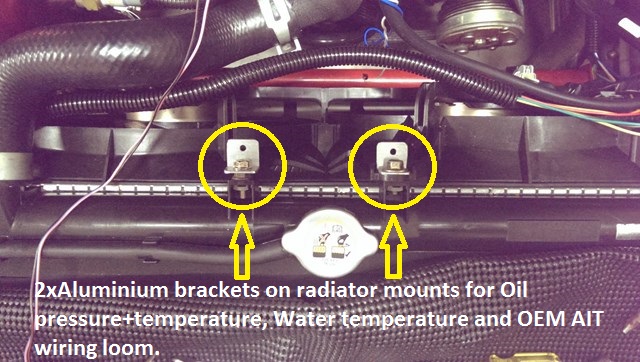
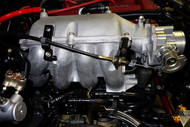
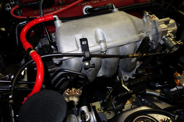
Here's the BEFORE (AEM CAI) configuration, followed by the new annotated current configuration:
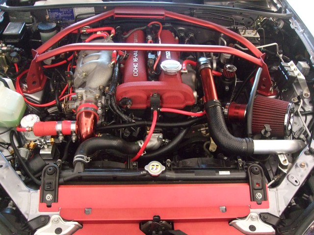
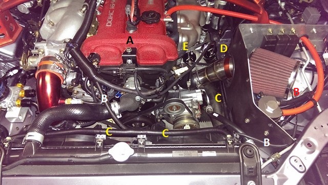
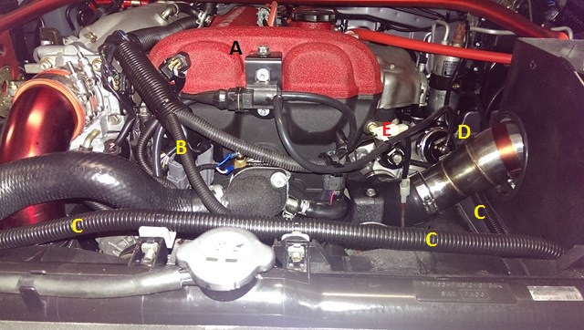
A: EFR6258 EBC solenoid mounted to DIY bracket (note that the angle cut on the left of the bracket is required to fit the diagonal OEM lip of the bracket mount point)
B: OEM AIT wiring (the water temperature wiring, blue+white wires attached to the Maruha water thermostat adapter, feed into the same split loom)
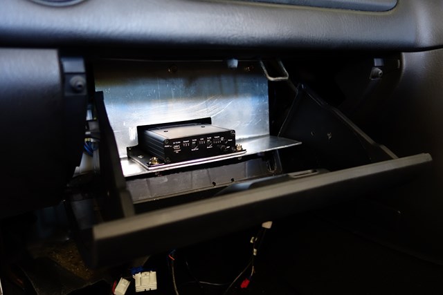
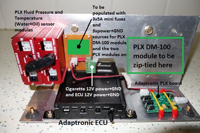
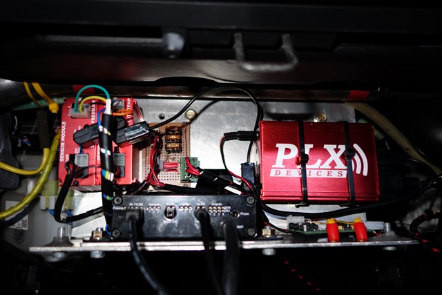
C: Oil Pressure+temperature, water temperature and OEM AIT wiring loom (runs parallel to radiator, then down and along parcel shelf, behind Cold Air Box and through the grommet in the firewall to the glovebox-mountes PLX sensor modules)
D: TurboSmart wastegate actuator
E: TurboSmart BOV (hose is routed behind engine on the firewall
This week I think I need to paint Dann's intake pipe Metallic Red - just to balance the colouring of the throttle body elbow
Originally posted by Okibi, Sun Feb 09, 2014 1:00 am[
Looks great, but less tinkering and more running in! I wanna see your SE running full boost!
Originally posted by Nevyn72, Sun Feb 09, 2014 8:03 am[
Lokiel wrote:This week I think I need to paint Dann's intake pipe Metallic Red - just to balance the colouring of the throttle body elbow
You know I was just about to post exactly this!!
How many more Km until you've run the engine in?
I mean all the pictures and neatness in the engine bay are nice but there's only one picture we all want to see...... A Dyno graph!
Originally posted by Lokiel, Sun Feb 09, 2014 10:20 am[
Okibi wrote:Looks great, but less tinkering and more running in! I wanna see your SE running full boost!
Agreed!
Unfortunately the Idling has turned to crap now (worse than when I took it home from MX5 Plus). This is probably due to the fact that the VTCS has been deleted and "Yonks ago" I switched the Adaptronic VTCS and Idle Control jumpers to Factory Control rather than Adaptronic Control (lassi at mazda-speed.com found that using the OEM ECU to control Idle and VTCS worked much better). I suspect with my current modz that the OEM ECU is now completely "out of whack" and has no chance of Idling the engine correctly.
Today's job is to switch those jumpers back to Adaptronic Control (like the photo below) and get her idling nicely again:
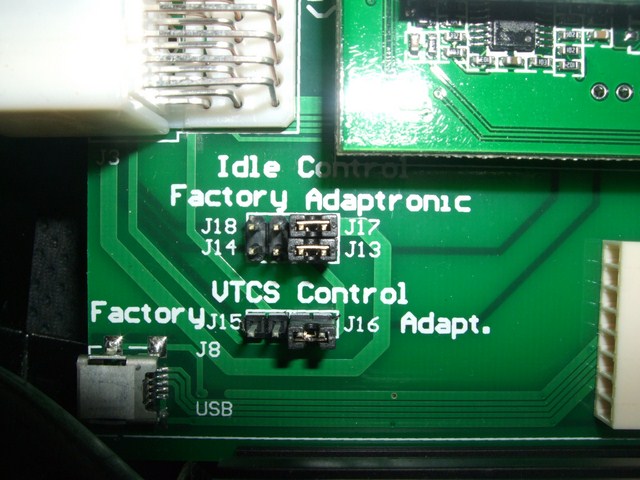
ie.
Idle Control: J14+J18 -> J13+J17
VTCS Control: J15->J16
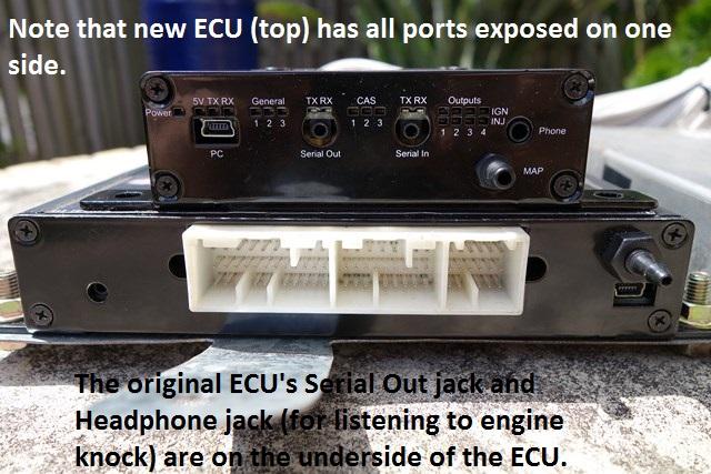
Changing those jumpers back is going to be a pain in the arse since I have to pull the Adaptronic ECU out of the car to get at them (the top plate of the ECU slides in place rather than screws on top so I need to take it out completely).
Originally posted by Lokiel, Sun Feb 23, 2014 10:18 pm[
I was politely asked NOT to do any car tuning on Saturday (involves spending lots of time with your car running and revving it) since one of the units in my townhouse complex was being shown to several prospective buyers so I took the opportunity to rewire the A/C power and paint Dann's CAI pipe red to match his "now Red" throttle body elbow.
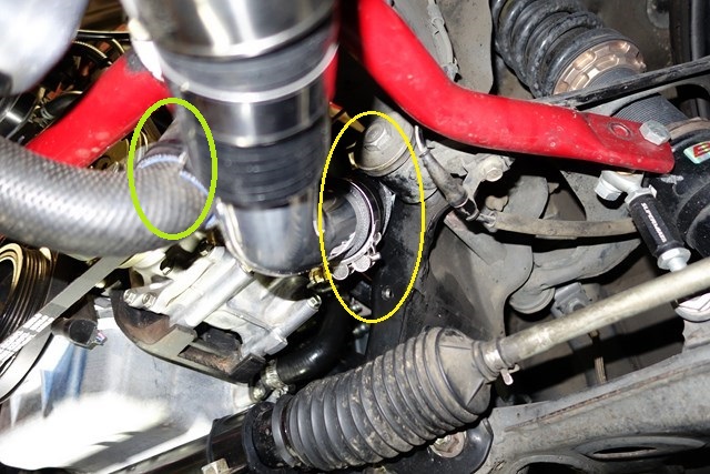
The OEM A/C power wire runs across the front of the engine, then straight down and to the rear of the A/C compressor, as highlighted in yellow below:
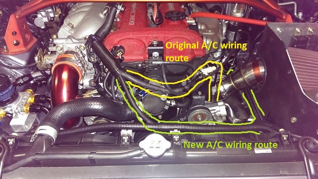
With the P/S in place, this wire was hidden from view but since I removed the P/S, that wire just cuts through a large vacant space and goes under the intake's turbo silicon hose, pulling a little too tight for comfort.
Since I now route a lot or wires along the rear of the radiator and through the passenger-side firewall, I could simply extend the A/C power wire and run it through this harness, exiting as close to the rear of the A/C compressor as possible, as highlighted in green in the above photo (the anti-clockwise "J", behind the CAI pipe, is where it exits the harness and connects to the OEM A/C power's single blade-pin).
Once again I used VHT's Red anodised colour coat but this time finished it with 5 thin coats of Clear Acrylic Top Coat to protect the metallic finish since the throttle body elbow scratches easily. I figured that air going in would be colder through the intake pipe would be cooler than at the elbow so the topcoat would be less likely to burn/melt. As it turns out, after a long run, the heat coming from the manifold seems to heat the intake pipe up quite a bit so I'll need to keep an eye on it. Here's what it looks like:
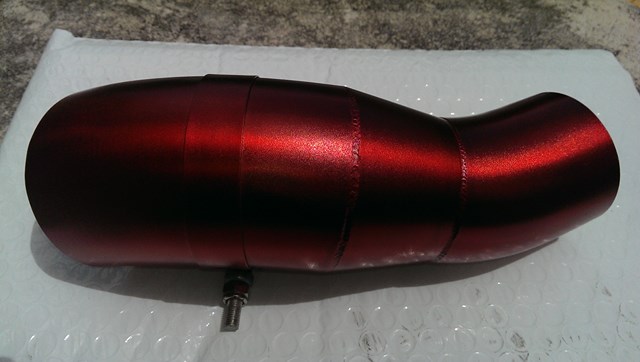
The worm clamp is used to hold the pipe in place inside the Cold Air Box - it's held by a DIY 90* aluminium bracket that sits on a rubber mount; the threaded part fits through the bracket and is held in place by a nylock nut. It's simple and works very well.
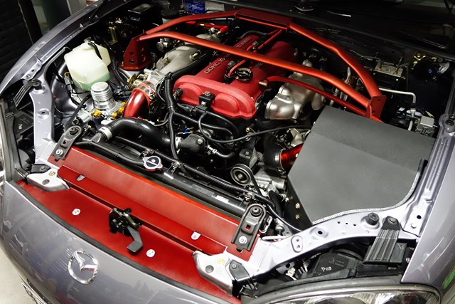
Here's the "almost finished" engine bay:
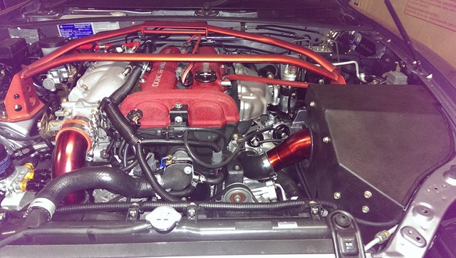
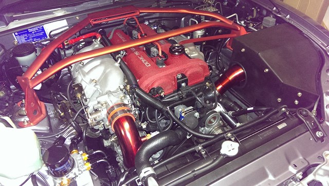
It's "almost finished" since I want to repaint the Beatrush radiator panel since it's a bit scratched - I plan to topcoat it too to finish it off.
Not sure if anyone noticed, but my oil cap has changed in previous photos from a Mazdaspeed Miata (MSM) cap, to an OEM cap to a CNC Mazdaspeed cap. Jason at MX5 Plus replaced my MSM cap with an OEM one because it was leaking and said it probably just needed a new O-ring. I always thought the MSM oil cap looked too big and don't really like the OEM plastic cap so bought an eBay CNC version with a Mazdaspeed badge. Hopefully this wont leak!
So how much space did the P/S removal and rewiring clear up? I think this photo illustrates it quite well:
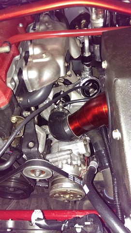
You could get a Sherrin footy in there easily!
