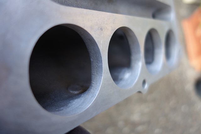
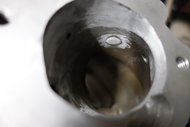
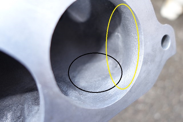
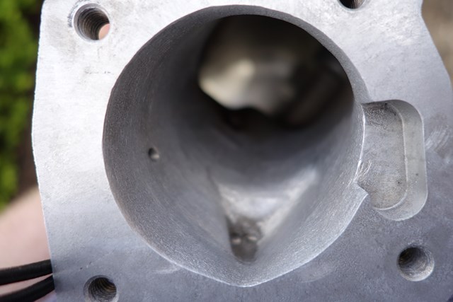
Lokiel's "Gina" (2004 Titanium SE)

Chat to do with your MX5/Miata/Eunos Garage Ride(s).

Moderators: timk, Stu, zombie, Andrew, The American, Lokiel, -alex, miata, StanTheMan, greenMachine, ManiacLachy, Daffy

User avatar
Lokiel
Forum legend
Posts: 4126
Joined: Thu May 28, 2009 2:39 pm
Vehicle: NB SE
Location: Brisbania

Re: Lokiel's "Gina" (once a 2004 Titanium SE) Recreated AGAIN

Postby Lokiel » Tue Jun 05, 2018 8:09 pm

Originally posted by Lokiel, Sun Sep 24, 2017 4:33 pm

Originally posted by Lokiel, Sun Feb 09, 2014 12:03 am[

I finally got around to mounting the EFR6258 EBC today and did some wiring re-routing.

The EFR6258's EBC normally mounts to the turbo intake housing but won't fit with the way my turbo is clocked so I decided to mount it on the front of the rocker cover, on the bolt-point of the OEM EBC. I made the bracket during the week and painted it black, spraying a new coat in the morning and night - unfortunately I've long since run out of Wrinkle Black and it hasn't been available for months so I just used some roll bar black.

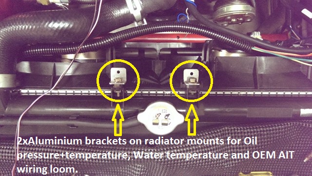
My Oil pressure+temperature, water temperature and OEM AIT wiring loom originally ran across the front of the rocker cover and under the AEM intake pipe but with the new EFR6258 and its EBC hoses, and Dann's intake, it still looked a bit cluttered (even without the P/S) so I decided to clean it up.

I originally allowed for enough wiring length to allow the loom to be routed along the front of the engine bay but was unsure about whether or not I could do this with the OEM AIT sensor wiring - luckily it did reach the intake filter without me needing to modify my Cold Air Box.

The wiring harness was mounted to the radiator mounts using some DIY Aluminium L-brackets - and zip-ties of course:
Image


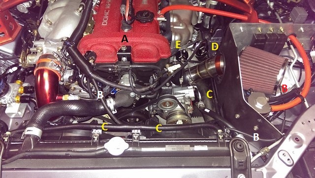
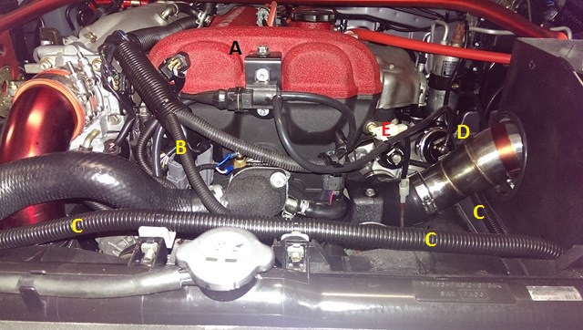
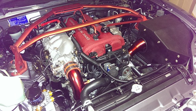
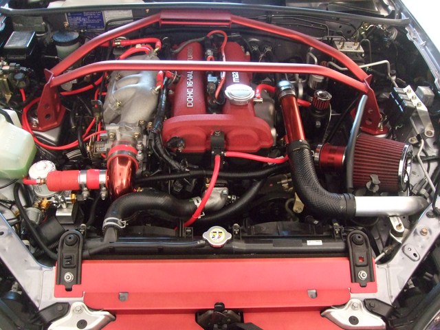
Here's the BEFORE (AEM CAI) configuration, followed by the new annotated current configuration:
Image


Image

Image


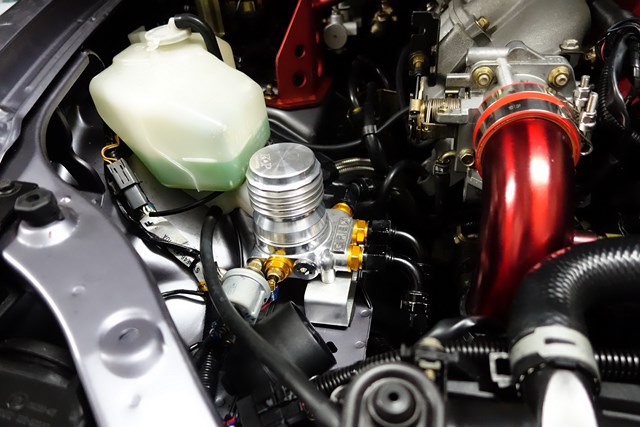
A: EFR6258 EBC solenoid mounted to DIY bracket (note that the angle cut on the left of the bracket is required to fit the diagonal OEM lip of the bracket mount point)

B: OEM AIT wiring (the water temperature wiring, blue+white wires attached to the Maruha water thermostat adapter, feed into the same split loom)

C: Oil Pressure+temperature, water temperature and OEM AIT wiring loom (runs parallel to radiator, then down and along parcel shelf, behind Cold Air Box and through the grommet in the firewall to the glovebox-mountes PLX sensor modules)

D: TurboSmart wastegate actuator

E: TurboSmart BOV (hose is routed behind engine on the firewall

This week I think I need to paint Dann's intake pipe Metallic Red - just to balance the colouring of the throttle body elbow :P


Originally posted by Okibi, Sun Feb 09, 2014 1:00 am[

Looks great, but less tinkering and more running in! I wanna see your SE running full boost!


Originally posted by Nevyn72, Sun Feb 09, 2014 8:03 am[

Lokiel wrote:This week I think I need to paint Dann's intake pipe Metallic Red - just to balance the colouring of the throttle body elbow :P


You know I was just about to post exactly this!! :lol:


How many more Km until you've run the engine in?
I mean all the pictures and neatness in the engine bay are nice but there's only one picture we all want to see...... A Dyno graph! :wink:


Originally posted by Lokiel, Sun Feb 09, 2014 10:20 am[

Okibi wrote:Looks great, but less tinkering and more running in! I wanna see your SE running full boost!

Agreed!

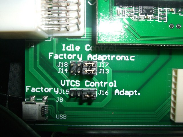
Unfortunately the Idling has turned to crap now (worse than when I took it home from MX5 Plus). This is probably due to the fact that the VTCS has been deleted and "Yonks ago" I switched the Adaptronic VTCS and Idle Control jumpers to Factory Control rather than Adaptronic Control (lassi at mazda-speed.com found that using the OEM ECU to control Idle and VTCS worked much better). I suspect with my current modz that the OEM ECU is now completely "out of whack" and has no chance of Idling the engine correctly.

Today's job is to switch those jumpers back to Adaptronic Control (like the photo below) and get her idling nicely again:
Image

ie.
Idle Control: J14+J18 -> J13+J17
VTCS Control: J15->J16

Changing those jumpers back is going to be a pain in the arse since I have to pull the Adaptronic ECU out of the car to get at them (the top plate of the ECU slides in place rather than screws on top so I need to take it out completely).


Originally posted by Lokiel, Sun Feb 23, 2014 10:18 pm[

I was politely asked NOT to do any car tuning on Saturday (involves spending lots of time with your car running and revving it) since one of the units in my townhouse complex was being shown to several prospective buyers so I took the opportunity to rewire the A/C power and paint Dann's CAI pipe red to match his "now Red" throttle body elbow.

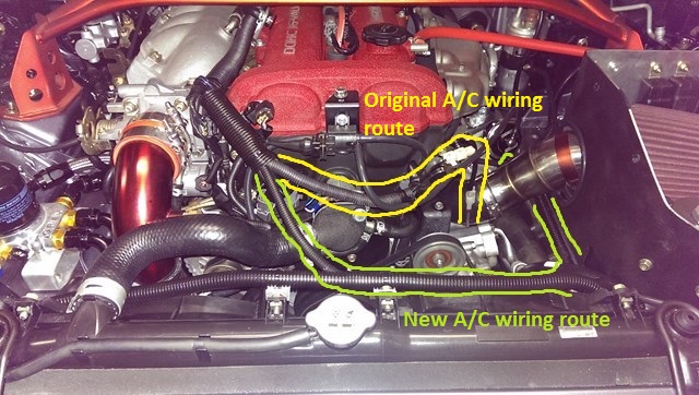
The OEM A/C power wire runs across the front of the engine, then straight down and to the rear of the A/C compressor, as highlighted in yellow below:
Image

With the P/S in place, this wire was hidden from view but since I removed the P/S, that wire just cuts through a large vacant space and goes under the intake's turbo silicon hose, pulling a little too tight for comfort.
Since I now route a lot or wires along the rear of the radiator and through the passenger-side firewall, I could simply extend the A/C power wire and run it through this harness, exiting as close to the rear of the A/C compressor as possible, as highlighted in green in the above photo (the anti-clockwise "J", behind the CAI pipe, is where it exits the harness and connects to the OEM A/C power's single blade-pin).

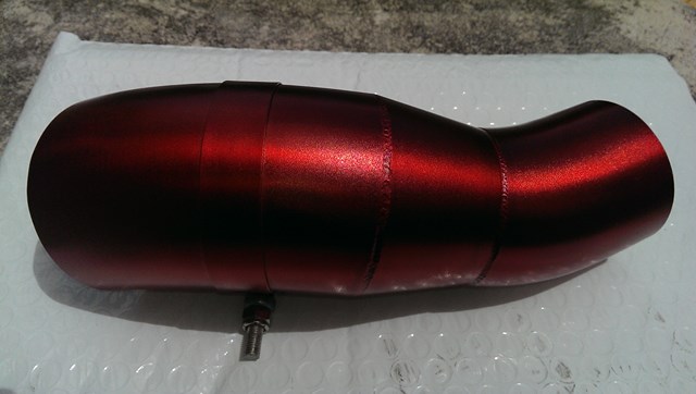
Once again I used VHT's Red anodised colour coat but this time finished it with 5 thin coats of Clear Acrylic Top Coat to protect the metallic finish since the throttle body elbow scratches easily. I figured that air going in would be colder through the intake pipe would be cooler than at the elbow so the topcoat would be less likely to burn/melt. As it turns out, after a long run, the heat coming from the manifold seems to heat the intake pipe up quite a bit so I'll need to keep an eye on it. Here's what it looks like:
Image

The worm clamp is used to hold the pipe in place inside the Cold Air Box - it's held by a DIY 90* aluminium bracket that sits on a rubber mount; the threaded part fits through the bracket and is held in place by a nylock nut. It's simple and works very well.

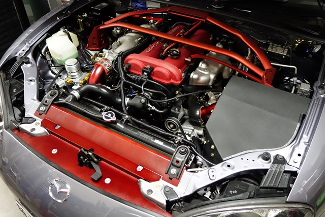
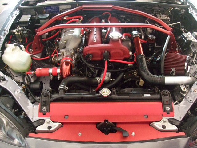
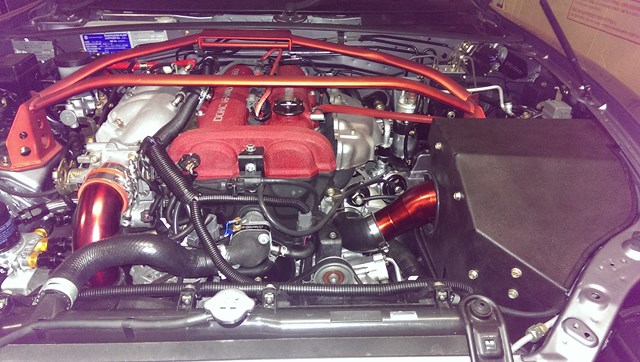
Here's the "almost finished" engine bay:
Image

Image

It's "almost finished" since I want to repaint the Beatrush radiator panel since it's a bit scratched - I plan to topcoat it too to finish it off.

Not sure if anyone noticed, but my oil cap has changed in previous photos from a Mazdaspeed Miata (MSM) cap, to an OEM cap to a CNC Mazdaspeed cap. Jason at MX5 Plus replaced my MSM cap with an OEM one because it was leaking and said it probably just needed a new O-ring. I always thought the MSM oil cap looked too big and don't really like the OEM plastic cap so bought an eBay CNC version with a Mazdaspeed badge. Hopefully this wont leak!

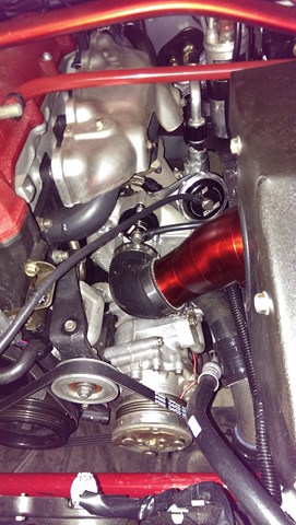
So how much space did the P/S removal and rewiring clear up? I think this photo illustrates it quite well:
Image

You could get a Sherrin footy in there easily!
Don't worry about dying, worry about not living!
Garage Thread: http://www.mx5cartalk.com/forum/viewtopic.php?f=57&t=76716

User avatar
Lokiel
Forum legend
Posts: 4126
Joined: Thu May 28, 2009 2:39 pm
Vehicle: NB SE
Location: Brisbania

Re: Lokiel's "Gina" (once a 2004 Titanium SE) Recreated AGAIN

Postby Lokiel » Tue Jun 05, 2018 8:09 pm

Originally posted by Lokiel, Sun Sep 24, 2017 4:33 pm

Originally posted by Lokiel, Sun Feb 23, 2014 10:51 pm[

Today was spent tuning the car. Last weekend I managed to get it idling reliably at 1,100rpm but that was just too high. It needed to be that high because when I engaged the A/C during idle (only when the fans weren't already running), the car would stall immediately at anything under 1,100rpm.

I spent every night during the week reading everything I could about tuning the Adaptronic and understanding what each setting affected, as well as an hour of tuning each night - this was probably why I was asked to take Saturday off :P

I finally got a reliable idle at 900rpm that wouldn't stall when the A/C was engaged or cycle the engine up and down wildly, mostly thanks to a tip from timk regarding a 450rpm "clamp" on the A/C. Now when I engage the A/C without any of the fans running, there is a noticeable rpm dip but it goes straight back to the idle speed and never stalls.

Once I'd sorted the Idle out, I configured the ECU to run in Rapid Learning mode and took the car for a decent spin. When you're "dicking around" with ECU settings, you need to take your tuning laptop with you so that you can revert to an earlier tune if something goes wrong (I needed it several times last weekend). Rapid Learning mode worked surprisingly well, the car idled well at stops and AFR readings looked reasonable while driving. I logged the data so that I could see what was really happening using MegaLogViewerHD once I got home. The log was mostly fine but there are still a few lean areas so more driving (and education) is required. I'm happy that the car is tuned safe enough to drive now so can finally take it for some longer drives and finish off the run-in period.


Originally posted by NitroDann, Sun Feb 23, 2014 11:46 pm[

boost pressure?


Originally posted by Lokiel, Mon Feb 24, 2014 10:27 am[

I've got the 10psi TurboSmart wastegate actuator spring in at the moment Dann but am keeping the RPMs below 4,000 during the run-in phase and I haven't seen more than 7psi on the boost gauge yet - it may have gotten higher but I haven't noticed or specifically noted it yet.

Even with these restrictions, it does feel quicker than the stock turbo at 13psi so I can't wait until I run te car in and can get it tuned properly. I plan on using Bradley Smith from Turning Point Technology in Pialba since he's an Adaptronic guru - to get the most/best out of any ECU you really need a specialist in that ECU.


Originally posted by sailaholic, Mon Feb 24, 2014 12:38 pm[

You should be able to have no idle drop with the ac, mine handles it ok and has less torque at idle then your I would think.

Have you got extra rpm keyed for ac request ( I run an extra 200 rpm idle with ac on).


Originally posted by Lokiel, Mon Feb 24, 2014 1:12 pm[

sailaholic wrote:You should be able to have no idle drop with the ac, mine handles it ok and has less torque at idle then your I would think.

Have you got extra rpm keyed for ac request ( I run an extra 200 rpm idle with ac on).


I've currently got "Idle -> Closed Loop Idle Control -> Extra For A/C( RPM)" set to 150 so will try bumping this up tonight as suggested. The dip is only momentary and to be honest, I'd simply "had enough" of tweaking the various settings to prevent the car stalling when the A/C was activated without the fans on and just wanted to drive the car.

If you have any other tips, please keep them coming. I've leaned a LOT doing this myself and actually making the time to do so (at the expense of my garden and housework mostly :P )


Originally posted by Magpie, Mon Feb 24, 2014 1:46 pm[

I know that feeling about stopping tinkering and just driving. It is so much more enjoyable :)

I just put off the small jobs and eventually get around to them when I feel like it...


Originally posted by gslender, Mon Feb 24, 2014 9:10 pm[

Lokiel wrote:I've currently got "Idle -> Closed Loop Idle Control -> Extra For A/C( RPM)" set to 150 so will try bumping this up tonight as suggested. The dip is only momentary and to be honest, I'd simply "had enough" of tweaking the various settings to prevent the car stalling when the A/C was activated without the fans on and just wanted to drive the car.

If you have any other tips, please keep them coming. I've leaned a LOT doing this myself and actually making the time to do so (at the expense of my garden and housework mostly :P )


The AC idle code (in the firmware of the ecu) needs to be doing more than just raise the idle target rpm - it needs more air via the idle valve a few ms before the AC is switched on (to ensure the engine has the torque and is ready to take the load). That is how the latest Megasquirt MS2 and MS3 systems do it. I've had it where they can be tuned with no idle dips - it is easy and requires little more to make work.

Also, if you running an ECU that supports it, ensure you've got an extra advance bin in the idle area so that when the rpm drops at idle (below the idle target) the spark curve will automatically advance. This will combat any drop in idle and smooth it out heaps.

Also, make the idle a/f slightly richer - a rich tune will be a little less susceptible to idle dips.


Originally posted by NitroDann, Tue Feb 25, 2014 1:24 am[

1:23am, finished work.. OMG..

On the phone to Jasper at TurboSmart HQ and he asks me did I build Simon C's turbo setup..

Hell yeh I did. :) Small world.

Dann
Don't worry about dying, worry about not living!
Garage Thread: http://www.mx5cartalk.com/forum/viewtopic.php?f=57&t=76716

User avatar
Lokiel
Forum legend
Posts: 4126
Joined: Thu May 28, 2009 2:39 pm
Vehicle: NB SE
Location: Brisbania

Re: Lokiel's "Gina" (once a 2004 Titanium SE) Recreated AGAIN

Postby Lokiel » Tue Jun 05, 2018 8:10 pm

Originally posted by Lokiel, Sun Sep 24, 2017 4:35 pm

Originally posted by Nevyn72, Sat Mar 15, 2014 8:56 am[

Have you finished running in that new engine yet? :|


Originally posted by Lokiel, Sat Mar 15, 2014 10:08 pm[

Between work and being crook all last weekend, I haven't had much time to do any engine running-in but I have been busy when time allows:

One thing I've learned about using Adaptronic's Rapid Learning mode to auto-tune is that unless you've got an AFR sensor like the Innovate AFR sensors that report when their data is valid or not (typically after reaching operating temperature), the initial reported data is garbage and REALLY screws up your map. My PLX AFR sensor, like most AFR sensors, merely reports an analogue 0-5V range and it's data is garbage until the sensor has warmed up.

I kicked myself that I sold my original Innovate LC-1 sensor to james_95 and bought an Innovate AFR MTX-L sensor+gauge from Andy at Adaptronic.

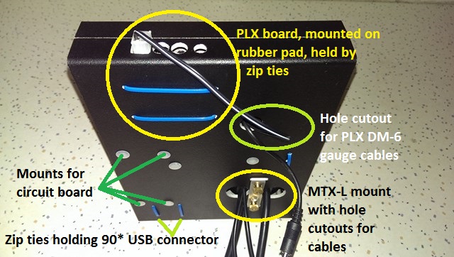
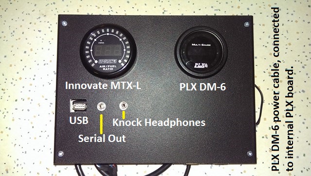
Previously I'd also bought the Adaptronic PLX board which allows Innovate AFR data to be input and reported by the PLX display modules (DM-100 and DM-6) so I decided to mount everything in a single box and mount it in the glovebox.

I also decided to provide easy-access connection points for the Adaptronic ports since the ECU was mounted behind the passenger-side kickplate and I really didn't want to have loose cables hanging around the footwell:
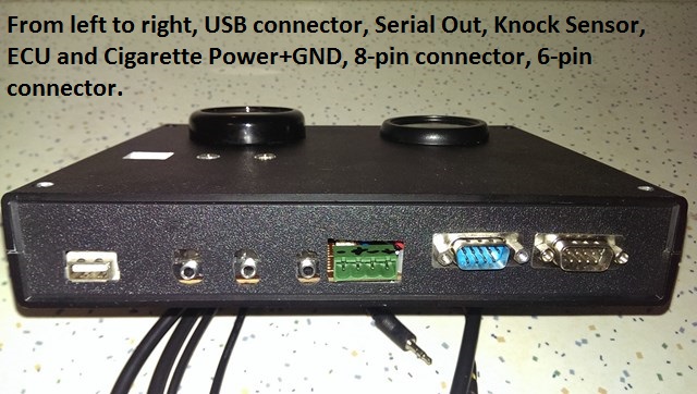
* Serial Output jack (left underside of ECU)
* Headphone jack for knock sensor (right underside of ECU)
* Serial In jack (right topside of ECU - used for Innovate AFR sensor input)
* USB port (left topside of ECU)
* Internal 8-pin header (made a cable connecting 8-pins to female DB-9 socket)
* Internal 6-pin header (made a cable connecting 6-pins to female DB-9 socket)

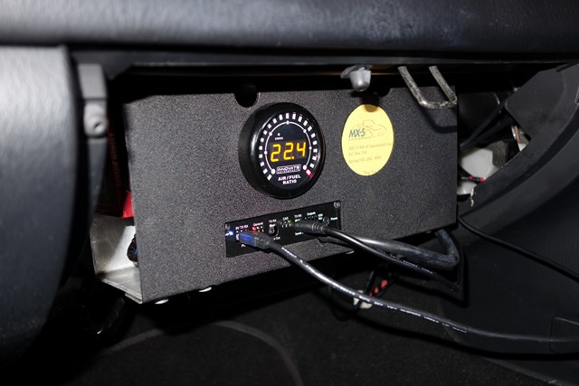
The only box Jaycar had that was big enough to house everything, and fit behind the glovebox, was "so 80's" beige so I gave it a few coats of Black Vinyl dye and assembled everything, including a circuit board to mount everything to and a 4-way fuse box for the PLX sensor and display modules.

So here it is all assembled, ready to mount on a backplate in the glovebox:
Image

Image

Image


In my correspondence with Andy regarding Idle tuning, he offered a swap of the original e440 Select ECU with the new model which is now a completely stand-alone ECU.
The original version needed to be a piggyback solution because it did not handle alternator control so this was passed onto the factory ECU.
Andy has now "licked this issue" so the new Adaptronic ECU handles it and I can "do away" with the factory ECU - WooHoo!

Needless to say, I took Andy up on his offer so this weekend's job is to rip out the original ECU and send it back to him.

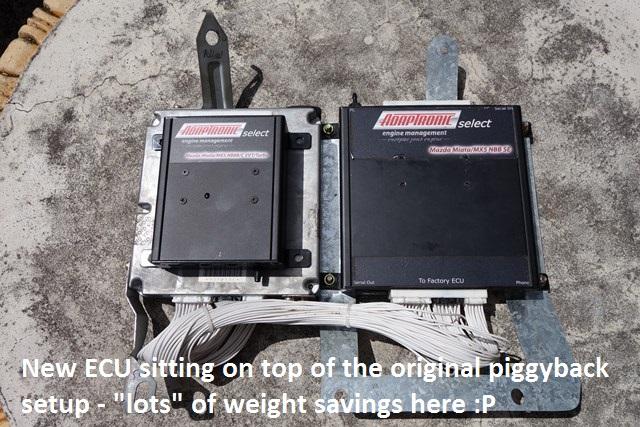
The new ECU is TINY, not much larger than a pack of cigarettes.

Here it is sitting on top of the factory ECU in my piggyback setup:
Image


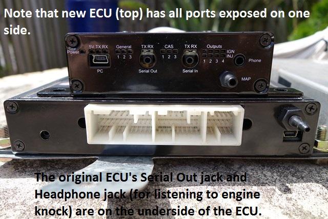
Here it is sitting on top of the original ECU:
Image

Note that all ports are located on the one side of the ECU - on the original ECU, the Serial Out and Knock jack are on the bottom-side of the ECU.

With the small size of the new ECU and all of its ports on the same side, I decided to mount the new ECU in the glovebox horizontally, with the ports (and LEDs) facing outwards.
Unfortunately this means that the box I created above has more "crap" in it than I need :(

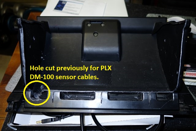
I started by Dremelling out the rear of the glovebox to allow a mounting plate to be installed behind the glovebox:
Image

I wanted to make the mounting plate as large as possible to give me more real-estate to mount stuff onto so the whole rear of the glovebox had to go.

Figuring out how to mount the backplate was a pain in the arse.
I planned to do something similar to mrpham's ECU-in-glovebox-mount solution so spent a lot of time making carboard templates, figuring out what would and wouldn't work.
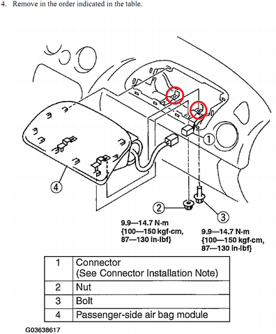
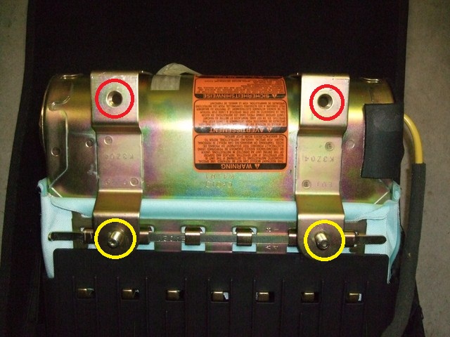
The only real mount points available were via the airbag's bolts (images re-used from earlier in this thread):
Image

Image

The red-circled threaded bracket holes are the rear of the airbag module where I decided to mount my backplate to; the yellow-circled bolts are on the opposite side of the safety bar.

Mounting a backplate to these rear threaded bracket holes was going to be impossible since there is no way to screw them in - the backplate would make access impossible.
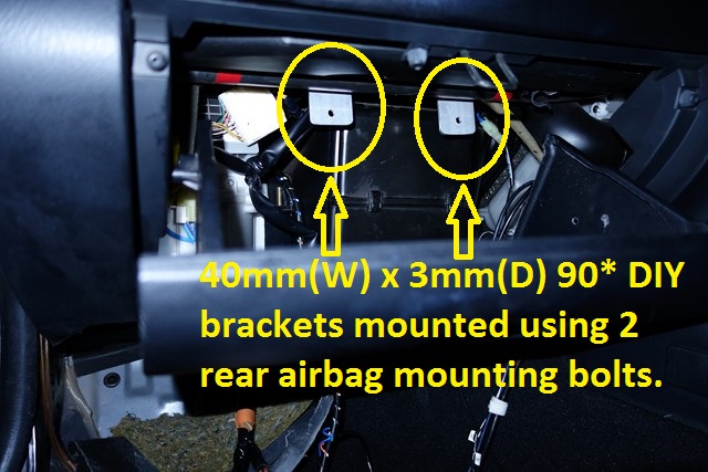
I needed to make two short 90* brackets that would allow me to screw in the bolts to the airbag mounts, then I could bolt the backplate to the vertical bracket section.
I made the 90* bracket using some 40mm wide by 3mm deep aluminium since they need to be strong:
Image


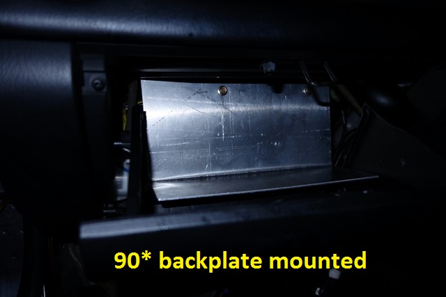
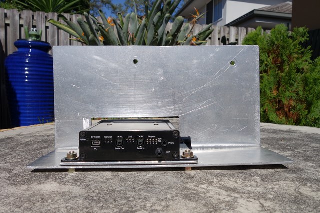
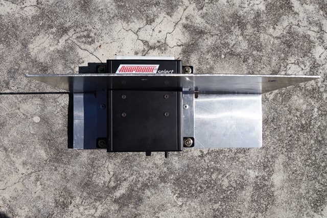
The rear mounting bracket design is limited by the reach of the factory ECU harness and the available room behind the glovebox fascia and I made it from the leftover 3mm thick aluminium plate from my DIY Cold Air Box.
Image

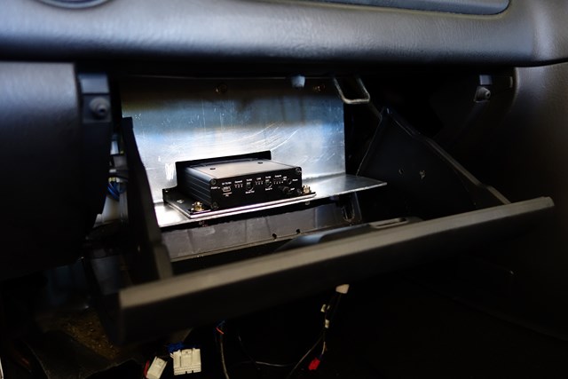
- Yes, the glovebox closes without touching the horizontal section of the backplate.

I made the backplate with a "shelf" so that I can mount the Adaptronic ECU to it but I'll need to cut a hole in the rear of the backplate since the ECU is longer than the shelf and it needs one anyway so that the ECU harness can connect to it.

Tomorrow's job is to fit everything else onto the backplate. I'm hoping to be able to cut-down the box I made above and mount it on the backplate too so maybe all that effort wont be wasted.


Originally posted by Nevyn72, Sun Mar 16, 2014 7:59 am[

I think my head just exploded trying to understand all that! :shock:

So basically you're upgrading to the standalone ECU, installing an Innovate AFR gauge and PLX sensor board and DM-6 gauge and putting the whole lot inside the glovebox?
Wouldn't you want the DM-6 out in the open where you can monitor it?


Originally posted by ManiacLachy, Sun Mar 16, 2014 10:02 am[

Jebus, you do some impressive work!

A lot of that went over my head, but I came away with the same understanding as Nevyn, and the same question.


Originally posted by Lokiel, Sun Mar 16, 2014 10:37 am[

Nevyn72 wrote::So basically you're upgrading to the standalone ECU, installing an Innovate AFR gauge and PLX sensor board and DM-6 gauge and putting the whole lot inside the glovebox?
Wouldn't you want the DM-6 out in the open where you can monitor it?


Yes to the first question.

Next answer is a bit log-winded:

I have a PLX DM-100 gauge mounted in the OEM dummy water temperature gauge location - this gauge has a mode that can display up to 4 sensor values at once and I use it to display AFR, Oil Pressure, Oil Temperature and Water Temperature.

When I bought the PLX AFR Sensor module, there was a package deal with the AFR sensor module and the DM-6 module, a gauge that can display one sensor value at a time so I bought that and mounted the gauge on an A-pillar pod. When connected to the PLX DM-100 sensor module, the DM-6 gauge can display any sensor value the DM-100 sensor module can see (the DM-100 gauge is also connected to the OBDII port so can report any of these values); you cycle through the values using a touchspot on the DM-6 gauge.

When pulled over for a breathalyser test, the friendly cop suggested that I should "probably" remove the A-pod gauge so I did to avoid subsequent issues - nobody wants that. This left me with a spare DM-6 gauge.

With the Adaptronic PLX board now accepting an Innovate AFR input and capable of displaying its value on the DM-100 or DM-6 gauge, I could switch to the Innovate AFR sensor. It was almost as cheap for me to buy the Innovate MTX-L which includes a gauge so I bought it - I don't really need its gauge since I can see the reading on my DM-100 gauge in the instrument cluster.

Since I now had to mount the PLX gauge and Adaptronic PLX board somewhere, and the PLX DM-6 gauge doesn't take up much room and requires minimal wiring with the Adaptronic PLX board installed, I figured I may as well make use of it, AND it has the added benefit of allowing me to easily see another sensor value that the PLX DM-100 Sensor can see. I've already got the most important gauges reported on my PLX DM-100 gauge so the DM-6 gauge will just be used for displaying occasionally viewed values (eg. I'd like a Volt gauge, it's something you like to see occasionally).

Bottom line: I can already see the AFR value on my PLX DM-100 gauge that's located in the instrument cluster - I'm just making use of the previously unused PLX DM-6 gauge I had lying around to display occasionally read sensor data.


Originally posted by Nevyn72, Sun Mar 16, 2014 11:15 am[

Ahhhh.... I don't remember you posting anything about installing the DM-100 gauge in the instrument cluster, do you have a pic of it in there?
I imagine it stands out a bit being so different from the rest of the cluster.....

I was considering sacrificing the water temp gauge in the cluster as well but will probably keep it and mount a proper temp gauge elsewhere.
The thought being that the factory gauge indicates when things are 'generally ok' but have proper gauge to refer to when stuck in traffic or other times of potentially high levels.


Originally posted by Lokiel, Sun Mar 16, 2014 11:25 am[

Nevyn72 wrote:Ahhhh.... I don't remember you posting anything about installing the DM-100 gauge in the instrument cluster, do you have a pic of it in there?
I imagine it stands out a bit being so different from the rest of the cluster.....

I was considering sacrificing the water temp gauge in the cluster as well but will probably keep it and mount a proper temp gauge elsewhere.
The thought being that the factory gauge indicates when things are 'generally ok' but have proper gauge to refer to when stuck in traffic or other times of potentially high levels.


See page 13.

The OEM dummy water temperature gauge is really only a binary gauge, it only reports high temperature when it's already way too high so is useless.

This simple linear gauge mod turns the dummy gauge into a more useful gauge since the needle moves linearly as temperature increases:
http://www.mazda-speed.com/forum2/index.php/topic,21534.0.html
It's not accurate by any means but at least you'll see if your water temperature is getting too hot before it's too late.


Originally posted by Roadrunner, Sun Mar 16, 2014 9:24 pm[

That is....impressive!! :beer:

Your also using PLX sensors for the oil pressure and temp right? Is the adaptronic using these at all or are they just fed into the dm-6/100 for visual reference bypassing the ecu?

I was -><- this close to buying a PLX AFR/dm6 combo but your experience with the startup AFR issues has convinced me to go with the innovate (probably LC-2/BD gauge combo and utilise the PLX board with a plx OBD adaptor when I get the new ECU)


Originally posted by sailaholic, Sun Mar 16, 2014 9:42 pm[

The adaptronic can't use them now (it's limited to one extra temp input which is used by the dual air temps on the SE I believe?) but soon will via the innovate Sis-4 (I think I got the right model)

Does obd still work once the eom ecu us removed? I didn't think any of the standalone ecus supported obd data format.
Don't worry about dying, worry about not living!
Garage Thread: http://www.mx5cartalk.com/forum/viewtopic.php?f=57&t=76716

User avatar
Lokiel
Forum legend
Posts: 4126
Joined: Thu May 28, 2009 2:39 pm
Vehicle: NB SE
Location: Brisbania

Re: Lokiel's "Gina" (once a 2004 Titanium SE) Recreated AGAIN

Postby Lokiel » Tue Jun 05, 2018 8:10 pm

Originally posted by Lokiel, Sun Sep 24, 2017 4:35 pm

Originally posted by Lokiel, Sun Mar 16, 2014 11:19 pm[

Roadrunner wrote::
Your also using PLX sensors for the oil pressure and temp right? Is the adaptronic using these at all or are they just fed into the dm-6/100 for visual reference bypassing the ecu?
:

sailaholic wrote:The adaptronic can't use them now (it's limited to one extra temp input which is used by the dual air temps on the SE I believe?) but soon will via the innovate Sis-4 (I think I got the right model)

Does obd still work once the eom ecu us removed? I didn't think any of the standalone ecus supported obd data format.
:


Currently I'm just using the oil pressure/temperature and additional water temperature for visual reference; sailaholic is right, the Adaptronic ECU can't use them yet (there are several free digital inputs available so in future, using an analogue->digital converter, the software could be updated to make use of them possibly for Power Cut control when engine oil gets too hot?).

The new NB ECU has a jumper on it that dictates whether the input on that pin is for VVT or for the SE's AIT2 sensor which is mounted on the throttle body elbow ; on a turbocharged car, the air entering the throttle body is what's important (the air temperature at the filter is not used). The original SE-specific ECU had this AIT2 sensor as well as a 0-5V analog input which I was using for my PLX AFR input - this input is now being used by the new ECU for alternator control so it can't be used for any PLX sensor inputs.

I hadn't even thought of losing OBDII functionality and just assumed it was still there - will confirm this once I've got everything running.


Unfortunately today I didn't get as much done as I wanted. I'd hoped to be able to cut-down the gauge housing I'd made earlier but I still needed to accommodate the PLX Temperature and Pressure modules as well as the large PLX DM-100 module within it and it just wasn't going to fit :(

I started the day cutting out the rear of the backplate for the Adaptronic ECU. Since the ECU's rear mounting points had nothing to mount to, I needed to add a plate underneath it:
Image

Image

If I'd put a bit more thought into the backplate, the rear cutout section is long enough to accommodate the ECU's rear mount points so the additional plate I added wouldn't have been needed - I could have have just cut the sides and top of the cutout section prior to bending the backplate.

Here is how it sits right now:
Image


I'd like to add an additional brace point at the bottom of the backplate, more for peace of mind than anything since it doesn't move much.

At least I can now work with the backplate outside of the car since it dictates the physical constraints I have to work with. My knees, elbows and abs are killing me from working under the dashboard and holding contorted positions for so long while figuring out what was and wasn't possible.


Originally posted by Magpie, Mon Mar 17, 2014 6:29 am[

Just make sure you do not open the glove box when pulled over :)


Originally posted by Nevyn72, Mon Mar 17, 2014 7:44 am[

Magpie wrote:Just make sure you do not open the glove box when pulled over :)

No, honestly officer, it's for the stereo! :mrgreen:


Originally posted by Lokiel, Tue Mar 18, 2014 5:20 pm[

sailaholic wrote::
Does obd still work once the oem ecu us removed? I didn't think any of the standalone ecus supported obd data format.
:

I had a couple of questions for Andy today and this was one of them, so straight from the horse's mouth:

"No, OBDII is not supported. I m thinking about it but it looks like a biggish job and I m not sure why people would want it. The only reason I can see is to use those off the shelf data readers (Bluetooth or wired) but OBDII is so slow but I m looking at adding it to add support for these 3rd party devices."

Note that Shell's AdaptiveTuner Android App can log Adaptronic data so you're not really missing out on anything if you want to see gauges and you're used to using Torque.


The other question was regarding the Wideband AFR sensor. Previously I was using the original Adaptronic Select ECU's 0-5V External Input for my AFR source but that is now used for alternator control so I suspected that the only AFR sensors that can now be used are the Innovate sensors, or any that provide a serial connector like the Innovate's do. Andy's response:

"You can also use a wideband input via the narrowband input if you scale it for a 0-3V signal, but yes you re right. We do prefer the Innovate for reasons I think you already know (serial, no ground offset problems, tells you the sensor status in the packet so the ECU can go open loop if the sensor fails or is cold, etc) but we should make that explicit on the web page."

ie. The Innovate AFR sensor is definitely the one you want for an Adaptronic ECU.

I'll post this in the "Adaptronic Owners" thread too t o make it easier to find.

The real bummer for me is that my PLX DM-100 gauge ALWAYS tries to connect to the OBDII port at startup which takes a few seconds; then it will start reporting my non-OBDII data that I have selected for display (AFR, Oil Pressure, Oil Temperature and Water Temperature). Oh well, I can live with that I guess.


Originally posted by Lokiel, Sat Mar 22, 2014 10:58 pm[

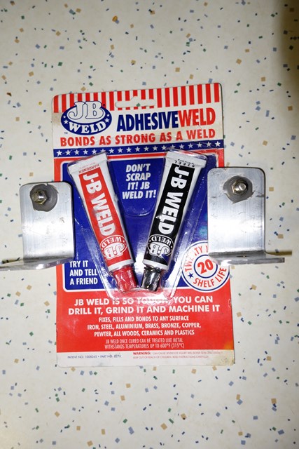
After dropping a nut trying to mount the backplate for the "ump-teenth" time during the week, I decided to JB-Weld them in place - much better:
Image

Note: The brackets are upside-down in this photo and face the other way (ie. the nuts face the front of the car).

I've been shuffling all my gauge components around during the week, trying to figure out how to get everything to fit on the backplate I made.

The biggest hassle is the PLX DM-100 sensor module, it's quite large and has connectors on both ends, including a VGA cable (which requires about 50mm alone for the connector) for the DM-100 gauge I have mounted in the instrument cluster.

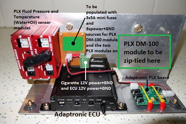
In the end, the only solution was to cut the right hand side of my remaining glovebox enough so that the cable could stick out past it and give me enough room to mount the PLX DM-100 sensor module. I STILL haven't figured out a good way to mount it so it will be zip-tied in place again (you can see the 4 holes pre-drilled for this below):
Image

*The DM-100 module is still wired into the cluster so I couldn't take it out easily to mount outside the car and will zip-tie it in place when I mount the backplate.
*The Adaptronic PLX board doesn't have mount-holes so it's sitting on 4 rubber feet and is zip-tied in place - the red silicon hose is to protect the board against rubbing from the zip-ties.
*I'm still waiting on some PCB mini-fuse holders for the two PLX sensor modules and DM-100 gauge from RS-components so for now, will only be able to use the PLX DM-6 gauge.
*I JB-Welded the bottom left and right nuts as well as the two top nuts on the rear of the backplate where you see those bolts - these are where the faceplate will be mounted to. Originally I planned to use Rivnuts/Nutserts but the JB-Welded nuts I did earlier in the week worked out pretty well and I've got plenty of 6mm nuts so why not use them?

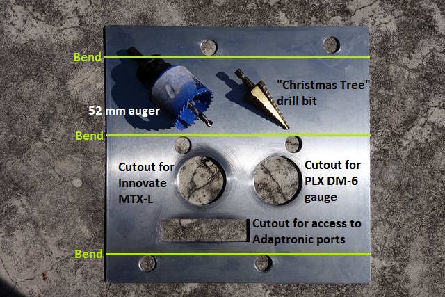
Next thing to do was a faceplate to mount the Innovate MTX-L gauge and PLX DM-6 gauge. I used some 2mm aluminium plate left over from the Cold AIr Box lid:
Image

When cutting holes it's MUCH simpler to use a hole-saw, 5 minutes with a hole-saw and files gets a pretty circular hole - vs 30-60 minutes with drills, a jigsaw and files which will produce an almost circular hole. If you're in Brisbane and ever need to borrow a metal 52mm hole saw, let me know, I can't see it getting much use just from me.
*The top two small holes are to fit over the backplate-mounting bolts.
*The bottom two small holes are to fit over the ECU mounting bolts.
*The middle two small holes are to allow access to the faceplate bolts where it mounts to the backplate - I need to use a long extension+magnetised socket.

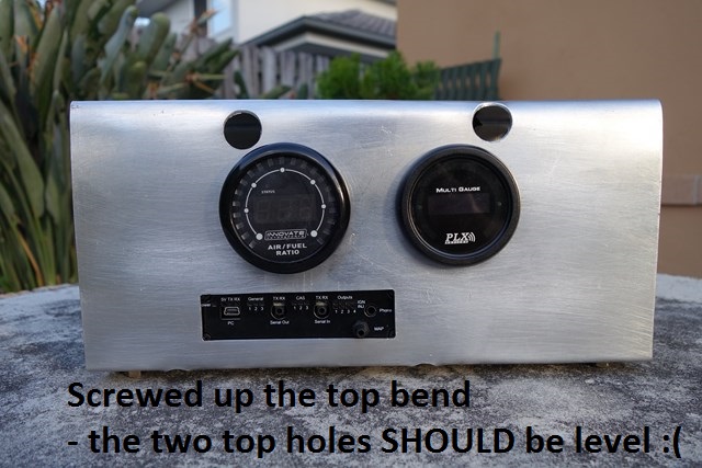
Here it is all bent into shape with the gauges mounted:
Image


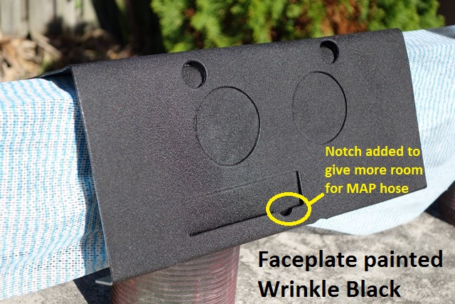
Tomorrow I plan to paint it Wrinkle-Black and swap the PLX Wideband O2 sensor with the Innovate MTX-L sensor (and hopefully do a little tuning).


Originally posted by Okibi, Sun Mar 23, 2014 3:30 am[

Great work :mrgreen:


Originally posted by KevGoat, Sun Mar 23, 2014 3:20 pm[

This stuff is way over my head ... but thoroughly enjoying the detail in this thread and build.


Originally posted by Roadrunner, Sun Mar 23, 2014 9:03 pm[

That's a pretty sweet setup. Love the use of the plx gauges. One guage, all your data.
Does the dm100 need to be plugged into the obd port for power?
I assume power would be the only thing going through the obd port now, maybe reporting voltage?


Originally posted by Lokiel, Sun Mar 23, 2014 11:26 pm[

Roadrunner wrote:That's a pretty sweet setup. Love the use of the plx gauges. One guage, all your data.
Does the dm100 need to be plugged into the obd port for power?
I assume power would be the only thing going through the obd port now, maybe reporting voltage?


The DM-100 sensor module is powered from a separate 12V source.
There is a VGA cable that connects the DM-100 display module to the DM-100 gauge and this provides power to the gauge.
The OBDII connection just provides data to the DM-100 display module.
This arrangement allows users to NOT connect the OBDII port if required.
Don't worry about dying, worry about not living!
Garage Thread: http://www.mx5cartalk.com/forum/viewtopic.php?f=57&t=76716

User avatar
Lokiel
Forum legend
Posts: 4126
Joined: Thu May 28, 2009 2:39 pm
Vehicle: NB SE
Location: Brisbania

Re: Lokiel's "Gina" (once a 2004 Titanium SE) Recreated AGAIN

Postby Lokiel » Tue Jun 05, 2018 8:10 pm

Originally posted by Lokiel, Sun Sep 24, 2017 4:36 pm

Originally posted by Lokiel, Mon Mar 24, 2014 12:10 am[

I painted the Faceplate Wrinkle Black today - Brisbane gave me another hot day today so I just left it to bake in the sun between coats:
Image


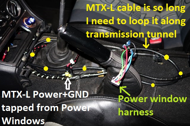
Today's big job was to install the Innovate wideband sensor and calibrate it:
Image

*For power, I vampire-tapped the power windows 12V+GND - this is a switched power source and a LOT easier to access than the cigarette 12V+GND.
*The MTX-L cable is VERY long so I looped the excess length along the length of the transmission tunnel (highlighted with yellow dots above).

I've installed 3 Wideband sensors in my car now, Innovate LC-1, PLX AFR sensor and now the Innovate MTX-L sensor.
Of all of these, I prefer the original LC-1 since it had a separate power+GND source for the heater element (ie. less noise to affect sensor readings) and it was simple to shorten the cable - making a box to house the calibration button+LED and accept all wiring made installation "a doddle" (see 2nd post in james_p93's thread: http://mx5cartalk.com/forum/viewtopic.php?t=60029).
There is a 4x2 multi-pin connector on the MTX-L unit and I really didn't want to go through the hassle of shortening it.

It took me about 45 minutes to thread the bloody AFR sensor into the bung since I could only reach it around NitroDann's 3" downpipe with just my fingertips. The bung is mounted about one o'clock so "the trick" was to align myself with the bung, pull down on it with a finger on each hand and turn it with my other fingers until it was in as far as possible, then finish it off with a 7/8" spanner - it's definitely an odd sized spanner but that seems to be the standard for Wideband O2 sensors.

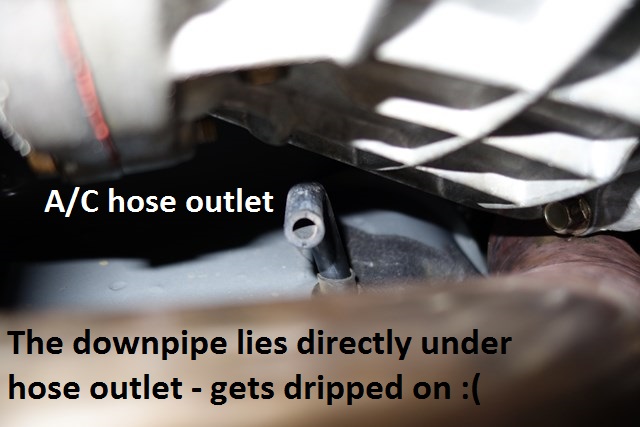
While I was under there, I noticed that my A/C hose outlet drips onto my downpipe just as timk found:
Image


That's a pretty piss-poor design and I wasn't going to leave it like that so I needed to extend the hose below the level of the downpipe.
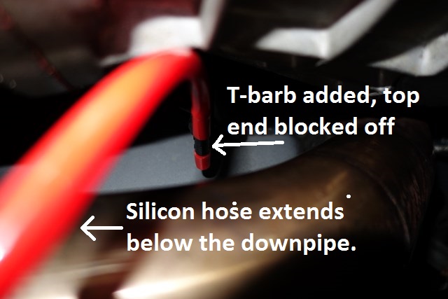
It's REALLY hard to get at and I initially tried to slide a larger heater hose over top of it but none of mine would fit.
In the end I used a T-Junction barb, that was the only one I had that fit the hose, blocked off one end and attached a silicon hose to the other end to allow it to extend below the downpipe:
Image

There's nowhere to attach the end to so it's just hanging but the hose's arc curves around the downpipe so it should be OK.

I was surprised to find that even without the Adaptronic ECU connected, I could power up the MTX-L unit and calibrate it - the power windows at least are independent of the ECU.

All this took longer than I expected so I didn't get time to do much more than this.

Hopefully the PCB mini-fuse connectors will arrive tomorrow so I'll hold off final installation until they've been soldered onto the PCB.


Originally posted by Nevyn72, Mon Mar 24, 2014 8:22 am[

So where did you run the line from the O2 sensor into the cabin?
I imagine it would have been too big to fit through one of the gromets in the firewall.....


Originally posted by sailaholic, Mon Mar 24, 2014 9:15 am[

I thought the whole point of the digital out of the innovate is that it didn't suffer signal noise from having the same ground.


Originally posted by Lokiel, Mon Mar 24, 2014 9:53 am[

Nevyn72 wrote:So where did you run the line from the O2 sensor into the cabin?
I imagine it would have been too big to fit through one of the gromets in the firewall.....

The cable runs under the front of the shift boot - where the leftmost yellow dot is in the photo above. It's a pretty thick cable but the boot is rubber so flexes over the top of it.

sailaholic wrote:I thought the whole point of the digital out of the innovate is that it didn't suffer signal noise from having the same ground.
:

Innovate have digital AND analog output lines.
The digital signal was implemented for ECUs to allow them to know when the data is valid or not - Innovate use their own protocol which digitises the analog sensor reading and passes that on in digital format, along with various other data, including whether or not the sensor reading is actually valid.

The original LC-1 had separate power and GND lines for the heater module component and the sensor but their printed instructions said to simply attach the GNDs to the same point.
The heater component draws a lot more power than sensor modules require.
A lot of electrical gurus pointed out that this would introduce additional noise to the sensor readings and if you search around on the Innovate forums, you'll see that their own tech guys DO recommend separate GND points, preferably with the sensor GND being connected to the same point as the ECU sensor GND point.
Innovate should have simply updated their Quickstart and Installation manuals to point this out but they never did and there's always a lot of questions/arguments about it.
To simplify everything, they now only have a single Power+GND source - it's definitely not ideal but maybe they've introduced some noise reduction circuitry into the new modules?


Originally posted by Nevyn72, Mon Mar 24, 2014 10:03 am[

The LC2 that now replaces the superseeded LC1 doesn't have separate grounds though?
Seems a strange way to go if their own tech guys believe they should be kept apart.....

I'll confirm as I have an LC2 on order, should be shipped today actually.


Originally posted by Lokiel, Mon Mar 24, 2014 11:37 am[

Nevyn72 wrote:The LC2 that now replaces the superseeded LC1 doesn't have separate grounds though?
Seems a strange way to go if their own tech guys believe they should be kept apart.....

I'll confirm as I have an LC2 on order, should be shipped today actually.


Just had a look at the LC-2 manual (http://www.innovatemotorsports.com/support/manual/LC-2_Manual.pdf) - you only have a single GND point.

I don't envy you trying to install the AFR sensor with a broken leg, you'll need to get in and out from under it several times - or are you planning on getting someone else to install it?

Also, do you have a bung on your downpipe to mount the sensor to?
The stock downpipe doesn't have one.
Some guys use the narrowband sensor location (it's mounted on the turbos' dump-pipe) for tuning purposes only, then put the Narrowband sensor back in and no longer can read Wideband AFR data. You DON'T want to leave the Wideband sensor there though since it's too hot and the sensor will not last very long.


Originally posted by Nevyn72, Mon Mar 24, 2014 4:45 pm[

Lokiel wrote:I don't envy you trying to install the AFR sensor with a broken leg, you'll need to get in and out from under it several times - or are you planning on getting someone else to install it?

Also, do you have a bung on your downpipe to mount the sensor to?
The stock downpipe doesn't have one.

Well I currently have a MX5-Mania 2.5" system installed which does not have a bung. :( (The factory one actually has one, it's in the middle of the catalytic converter!)

So I'm going to need to get one welded in (mid-way along the front pipe before the cat is the best place, right?) however it's going to be a bit time before I get it done so hopefully the leg will have healed enough by them it won't be such an issue to install the rest.....
Don't worry about dying, worry about not living!
Garage Thread: http://www.mx5cartalk.com/forum/viewtopic.php?f=57&t=76716

User avatar
Lokiel
Forum legend
Posts: 4126
Joined: Thu May 28, 2009 2:39 pm
Vehicle: NB SE
Location: Brisbania

Re: Lokiel's "Gina" (once a 2004 Titanium SE) Recreated AGAIN

Postby Lokiel » Tue Jun 05, 2018 8:11 pm

Originally posted by Lokiel, Sun Sep 24, 2017 4:37 pm

Originally posted by Lokiel, Sun Apr 06, 2014 11:03 pm[

Last weekend I was crook with the flu so didn't get a chance to do much.

I did discover the following things though:

1. You can't piggyback other PLX sensor modules onto the Adaptronic PLX board and display both Adaptronic and PLX sensor module data on the same gauge - you either have Adaptronic data or PLX sensor module data.

2. My PLX DM-6 gauge is stuffed - it displays a lot of static and the touch-spots don't work. I planned to display the Adaptronic data on this gauge and use my instrument cluster's PLX DM-100 gauge to display the PLX sensor module data (Oil Pressure+Temperature and Water Temperature - the 4th parameter is unused).

I hooked up the PLX-DM-6 gauge to the PLX AFR Sensor Module (I bought these 2 items as a package deal) on a bench and it did the same thing so I know it's not my wiring - I suspect I dropped the gauge sometime between taking it out of the car and now.

I'm not going to replace the PLX DM-6 gauge though since I plan on upgrading the PLX system later this year.


This weekend was much more productive, I finished up the glovebox gauge installation.

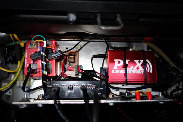
Here's everything installed on the mounting plate:
Image

You can see that there's a LOT of stuff mounted on the backplate - the circuit board REALLY tidies up the power wiring and the 3 mini-fuses take up virtually no room at all.

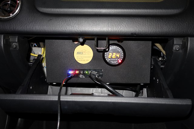
Here's the fascia installed, minus the glovebox:
Image

I needed to block off the other vacant gauge hole so used the logo from our QLD MX5 Car Club's magazine envelope - soon it will house a prototype multi-gauge.
The 3 attached cables are USB (for PC connection - this typically wont be connected, I'll use Shell's "Adaptive Tuner" on my Android phone for data logging using the Serial Output port), Innovate AFR (on Serial Input) and MAP source (boost/vacuum hose).

The housing is very solid - originally I thought I'd need a 3rd lower mounting/brace point but it's not necessary (and I have no idea where I could attach it).

I noted from the driver's seat that the glovebox "loop" obscured the Innovate AFR gauge a bit so I swapped the gauge to the other slot before fitting the glovebox lid:
Image

The glovebox shuts without "squishing" the AFR cable and MAP hose which is good since I thought I may have to swap the Adaptronic MAP's straight barb to a 90* barb and make a 90* adapter for the 2.5mm AFR Serial-In connection.

The unit looks much cooler WITHOUT the glovebox lid :(


I FINALLY got around to doing some initial tuning too which turned out to be much simpler this time around, partly because by now I have a good understanding of how to do an initial "rough tune" but I also suspect that the fact that the new Adaptronic Select ECU accepts an alternator input signal makes Idle control easier when the A/C is activated (previously most of my time was spent trying to stop the car from stalling when Idling and the A/C was activated).

I set the Adaptronic into "Rapid Learning" mode with the intent of driving around for a couple of hours but after about 10 minutes realised that a storm was imminent (something that's easy to "feel" in a convertible) so raced home with about 2 minutes to spare before a squall ripped through.

"Rapid Learning" will continue each night after work now - I need the car ready for the Nat Meet!

- No more modz until after then!


Originally posted by bootz, Sun Apr 06, 2014 11:09 pm[

This car is more of an epic than "Gone with the Wind" :)


Originally posted by NitroDann, Sun Apr 06, 2014 11:18 pm[

Rapid learning is only good for about 30 minutes if you drive through the entire map, which BTW you won't do unless you are intent on doing so. Just driving around won't nearly do it.

So then you need to interpolate. And then look at the map and use common sense to decide where it needs richening for safety reasons. And then use the slow converge setting to work back down from rich.

There is no easy way to rough out timing especially when your setup is so abnormal.

Dann


Originally posted by Lokiel, Sun Apr 06, 2014 11:38 pm[

NitroDann wrote:Rapid learning is only good for about 30 minutes if you drive through the entire map, which BTW you won't do unless you are intent on doing so. Just driving around won't nearly do it.

So then you need to interpolate. And then look at the map and use common sense to decide where it needs richening for safety reasons. And then use the slow converge setting to work back down from rich.

There is no easy way to rough out timing especially when your setup is so abnormal.

Dann


That's pretty much what Andy from Adaptronic recommends and he does state that it's no substitute for a proper tune.

While I'm running-in the car, the "Rapid Learn" + "Slow Converge" tuning modes will be sufficient, especially since I'm trying to limit myself to keeping the car under 4,000rpm during this period.

I do plan on making a lot of use of MegaLogViewerHD though.


Originally posted by timk, Mon Apr 07, 2014 10:16 pm[

I can imagine the flux capacitor poking through the unused hole on the right! :lol:
Don't worry about dying, worry about not living!
Garage Thread: http://www.mx5cartalk.com/forum/viewtopic.php?f=57&t=76716

User avatar
Lokiel
Forum legend
Posts: 4126
Joined: Thu May 28, 2009 2:39 pm
Vehicle: NB SE
Location: Brisbania

Re: Lokiel's "Gina" (once a 2004 Titanium SE) Recreated AGAIN

Postby Lokiel » Tue Jun 05, 2018 8:11 pm

Originally posted by Lokiel, Sun Sep 24, 2017 4:38 pm

Originally posted by Lokiel, Fri Apr 11, 2014 2:16 pm[

Wednesday and Thursday nights were the first dry nights we've had in Brisbane since I got everything installed on the weekend so I took the car for it's first test drive after doing the Idle tuning on Sunday - I didn't want to get stuck in the rain if something went wrong.

I started my Adaptronic Idle tuning on the weekend using the default N/A NB Fuel/Ignition maps and only "Mark as tuned" 6 cells cells prior to the initial drive using "Rapid Learning" mode (when cells are marked, the Adaptronic ECU can be configured to NOT modify them when in its auto-tune modes).

After my previous experiences I was expecting the initial drive to be "rough as guts" but was amazed at how smooth it was, no stumbling or stalling at all. I now have an OS Giken clutch in the car and it required a lot of concentration to NOT stall the car from a standing start - now it's not much different to the stock clutch, a little heavier and less forgiving but not terribly much.

I put this down to the following things:

1. The new Adaptronic ECU is a stand-alone ECU so now handles alternator input (alternator loads can vary a LOT).
2. I'm much more familiar now with the Adaptronic so my specific tweaks actually have merit (as opposed to just using what others found "might" help)
3. No more P/S (one less variable)
4. No more VTCS (MANY less variables during idling - supposedly the VTCS helps disturb incoming air to help burn fuel which improves vehicle emissions when Idling)
5. Innovate MTX-L AFR sensor rather than the PLX AFR sensor (the Innovate AFR serial output to the Adaptronic ECU lets it know whether or not the data being reported is valid' the PLX AFR sensor, like most other sensors, is analog only and will report garbage values until the heater component reaches operating temperature - this REALLY screws up the Adaptronic ECU's Fuel map when it's running in Rapid Learning mode).

The car now Idles at ~850rpm when previously I would need it to Idle at 1,000rpm to prevent stalls when the A/C was activated.
This caused me a bit of concern since now when I pull up to the lights, I have to check that the car hasn't stalled since it's so quiet and there's very little engine vibration (even with my new harder engine mounts) - this was with the top and windows DOWN!
A common problem I used to have when I had the original e440 Select ECU was that the car would stall when pulling up to lights, or even when just sitting at the lights - the engine would just stop cleanly with no surging/coughing/spluttering. Anthony from Kaizen garage fixed this but I could see the RPMs dip to 600rpm before jumping back to 1,000rpm - now it just smoothly drops to ~850rpm.

Jason from MX5 Plus said that during the run-in period I should keep the RPMs <= 4,000 and that I should try and exercise occasional surging too (as opposed to just driving smoothly like Miss Daisy would prefer) so that's what I've been doing.

Last night I changed the Adaptronic's "Rapid Learning" mode to "Slow Converge" mode and logged the data on my test drive.

When I got home I grabbed the logged data (it's in .csv format) and added a "Boost" column using Open Office Calc that had Boost values calculated from the corresponding MAP (kPa) cell (the formula is "[b]=IF(kPaCell<100;0;1+(kPaCell-100)*0.145037738)[/b]" where "kPaCell" is the kPa cell from which the boost value is being calculated, "100" kPa corresponds to 1psi (in the Adaptronic) and "0.145037738" is the actual kPa->psi conversion factor).

I was very surprised to see when I loaded the file into MegaLogViewerHD that my maximum boost level was 11.37psi at 3,727rpm (3rd gear).
This was with "heavy" engine oil at about half the RPM range - I can't wait to see what she'll do once I've run in the engine (hopefully that will be achieved during the NatMeet since I'll get a lot of opportunities to drive the car during that period).


Originally posted by bootz, Fri Apr 11, 2014 2:26 pm[

Reading the above, all I could think is 'genius' or 'aspergers syndrome', possibly both.


Originally posted by NitroDann, Fri Apr 11, 2014 2:41 pm[

So it was actually making 11.x PSI boost at 3700? Sorry I read it quickly.

Dann


Originally posted by timk, Fri Apr 11, 2014 2:43 pm[

bootz wrote:Reading the above, all I could think is 'genius' or 'aspergers syndrome', possibly both.


It reads fine/normal to me??


Originally posted by Lokiel, Fri Apr 11, 2014 3:22 pm[

NitroDann wrote:So it was actually making 11.x PSI boost at 3700? Sorry I read it quickly.

Dann


Yes - does that sound reasonable? It definitely surprised me.


Originally posted by bootz, Fri Apr 11, 2014 4:28 pm[

timk wrote:
bootz wrote:Reading the above, all I could think is 'genius' or 'aspergers syndrome', possibly both.


It reads fine/normal to me??


Well you can just
Lokiel wrote: "[b]=IF(kPaCell<100;0;1+(kPaCell-100)*0.145037738)[/b]"

off.


Originally posted by NitroDann, Fri Apr 11, 2014 4:59 pm[

ROFL:ROFL:ROFL:ROFL

Code: Select all

-----------------------
         _^___
 L    __/   [] \   
LOL===__        \
 L      \________]
         I   I
        --------/


Yeah that sounds right, its a serious bit of kit you have, pats setup on his 1.6L with T28 makes like 25PSI at 4200 or something. How hard does it pull at that rpm and boost?

Dann


Originally posted by Lokiel, Fri Apr 11, 2014 5:40 pm[

The "pushed back into the seat" sensation was significant enough for me to think I'd gone way over the 4,000rpm limit and I didn't rev it that hard after that.

On the two test drive tests I had a suspicion that the car was already close to what it was prior to turbo upgrade even with the 4,000rpm limit and the log file seems to confirm this.


Originally posted by NitroDann, Fri Apr 11, 2014 5:51 pm[

Wait until you get 30+psi in on a proper tune.

Image

(but at 200kph)


Originally posted by Okibi, Sat Apr 12, 2014 1:05 am[

NitroDann wrote:So it was actually making 11.x PSI boost at 3700? Sorry I read it quickly.

Dann


Getting that with the stock turbo .. :oops: and not much more.
Don't worry about dying, worry about not living!
Garage Thread: http://www.mx5cartalk.com/forum/viewtopic.php?f=57&t=76716

User avatar
Lokiel
Forum legend
Posts: 4126
Joined: Thu May 28, 2009 2:39 pm
Vehicle: NB SE
Location: Brisbania

Re: Lokiel's "Gina" (once a 2004 Titanium SE) Recreated AGAIN

Postby Lokiel » Tue Jun 05, 2018 8:11 pm

Originally posted by Lokiel, Sun Sep 24, 2017 4:40 pm

Originally posted by Lokiel, Fri Apr 18, 2014 6:22 pm[

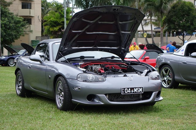
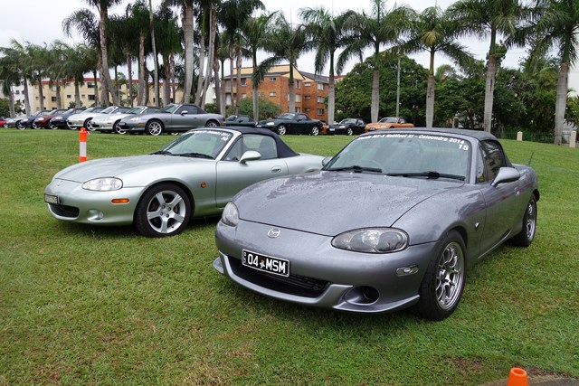
Here's a couple of photos of Gina from the 2014 Nat Meet Concourse:

Image

Image

Image


The last 2 were taken during lunch which is why no-one was around and the car's wet - thankfully the rain held off for the Concourse judging.

At the Concourse, all NAs and NBs, other than the 3 awesome NB specimens above, were in the top level of the carpark and all NCs were in the bottom level.

I like to keep my car as clean as possible but many of the cars at the Concourse really put Gina to shame (Mental note to self: NEVER park next to Mark Seville, his beautiful NA's interior looks more like an "upper-crust" English Gentleman's Club than the inside of a car - I'm surprised he doesn't drive it wearing a smoking jacket, holding a cigar in one hand and a glass of single-malt scotch in the other).

PS: I think I may have lost a few points for the "NitroDann" graffiti on the intercooler :P


Originally posted by bootz, Fri Apr 18, 2014 10:52 pm[

I would surmise the hydraulic bonnet struts are necessary because the car spends most of its time with the bonnet open.


Originally posted by Nevyn72, Sat Apr 19, 2014 12:29 am[

bootz wrote:I would surmise the hydraulic bonnet struts are necessary because the car spends most of its time with the bonnet open.

But where did he get the black ones from?.... The only one's I've ever seen listed for the MX5 are chrome.....


Originally posted by Lokiel, Tue May 06, 2014 9:05 pm[

There's been a bit too much black in the SE threads lately (see Okibi's and MINX's threads) so I reckon it's time to brighten things up a bit.

My Beatrush radiator panel was a bit beat up so I took it off for the NatMeet's concourse event and have finally resprayed it on the weekend. This time I made sure to finish it with acrylic topcoat to protect it. Previously I didn't do this which meant that the anodised finish tended to rub off when touched and it scratched very easily:
Image

I preferred the non-smooth anodised finish without the acrylic topcoat but it's just not durable enough.
The acrylic topcoat tends to deepen the colour too so in hindsight I should have used a few less coats of the anodised paint to leave it a bit lighter.

If you look in front of the radiator overflow bottle you can see my new K&N reusable oil filter "bling"; here's a close-up:
Image

I've had this for quite some time now and only just installed it after the engine has been run in.
See this thread for details: http://www.mazda-speed.com/forum2/index.php/topic,27291.0.html
That's my contribution to saving the environment :P

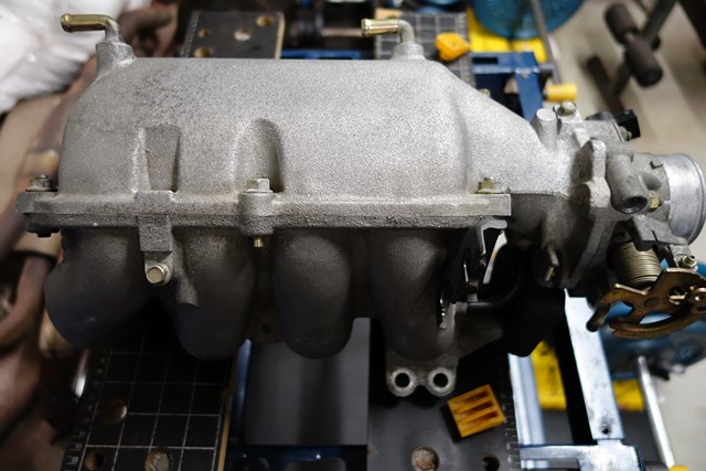
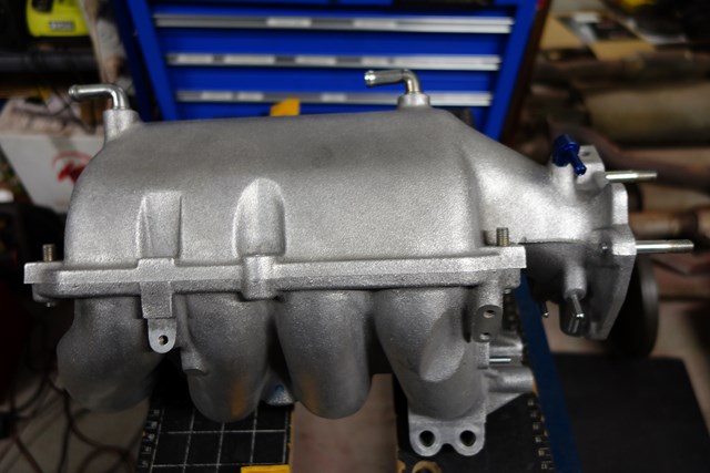
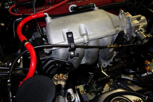
I'd been looking at Flattop/Squaretop intake manifolds for a while too and snapped up the one Keith had on offer recently - BEFORE:
Image


AFTER:
Image

It cleaned up nicely with some Ali-Brite and a wire-wheel spruce-up.

The manifold has fewer barbs on it than my VTCS manifold which now has most of the barbs either plugged or looped back to another barb after the VTCS delete so it'll clean up the engine bay a bit too by eliminating the redundant hoses.
I had MX5 Plus install another barb on top of the manifold behind the throttle body for my boost sensor (the top photo shows the "fitted-for-but-not-with" mount for it - the SP has this barb fitted) since now there isn't a spare barb for it and I'd prefer not to share the brake booster barb - much better to have a "clean" boost signal for the ECU.

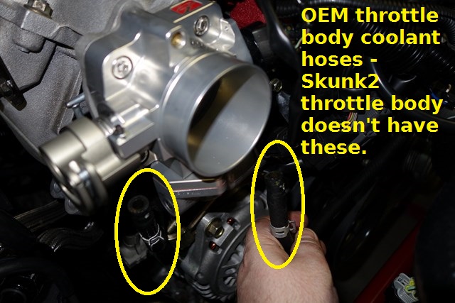
I've ordered a Skunk2 throttle body to go with this and will port the manifold to match its larger mouth.

I must be close to rivalling Nevyn72 now with parts on order or awaiting fitting:
* Fab9 COPs (have)
* Fab9 350HP intercooler (have - waiting for black silicon couplers to arrive)
* Squaretop intake manifold (have)
* Squaretop EGR block-off plates and gaskets (in the mail)
* Skunk2 throttle body (in the mail)
* Injector Dynamics 725cc injectors (next payday :( )

Apart from the intercooler, installing all of these at the same time will be more efficient and simpler so it's going to be a big weekend when I do.
I plan to mount the Fab9 COP Ignition Module on the shelf just in front of the brake booster which will be easier to access with the intake manifold reduced.

Once this is done I plan to FINALLY get the car professionally tuned to find out what she can really do.


Originally posted by plohl, Tue May 06, 2014 9:54 pm[

Any reason you went with the fab9 COP kit over the toyota COPs?


Originally posted by Lokiel, Tue May 06, 2014 9:59 pm[

^
Plug and Play mostly. The Honda boyz have been using these for a while now so they're reasonably proven.


Originally posted by plohl, Tue May 06, 2014 10:17 pm[

The CBR coils?


Originally posted by Lokiel, Tue May 06, 2014 10:21 pm[

Yep, the Fab9 pencil COPs were originally developed for motorbikes, then the VTEC "fanbois" started using them.


Originally posted by Nevyn72, Wed May 07, 2014 9:48 am[

Lokiel wrote:If you look in front of the radiator overflow bottle you can see my new K&N reusable oil filter "bling"; here's a close-up:
Image


Words can't describe how much I want one of those! :oops:
Isn't that the K&P version, the K&N item has smooth sides and about twice the already hideous price too....


uncited wrote:I must be close to rivalling Nevyn72 now with parts on order or awaiting fitting:

Well I've actually stopped ordering things for the moment...... I'm running out of cupboard space! :roll:


Originally posted by Lokiel, Wed May 07, 2014 11:26 am[

I did mean K&P oil filter.


Originally posted by Roadrunner, Wed May 07, 2014 4:21 pm[

That filter looks brilliant! Most people would look and not know what it was.
Don't worry about dying, worry about not living!
Garage Thread: http://www.mx5cartalk.com/forum/viewtopic.php?f=57&t=76716

User avatar
Lokiel
Forum legend
Posts: 4126
Joined: Thu May 28, 2009 2:39 pm
Vehicle: NB SE
Location: Brisbania

Re: Lokiel's "Gina" (once a 2004 Titanium SE) Recreated AGAIN

Postby Lokiel » Tue Jun 05, 2018 8:12 pm

Originally posted by Lokiel, Sun Sep 24, 2017 4:41 pm

Originally posted by Lokiel, Sat May 24, 2014 7:41 pm[

I finally had time to do some work on the car so decided to install the Fab9 350hp Intercooler.

I bought this instead of the Fab9 505hp version since I doubt that I'll ever push the car over 300hp on the track since that's where our gearbox tends to destroy itself and 300hp is "shedloads".
Bryan from Fab9 advised me that the 350hp version was more suited for my goals since the 550hp version would be a bit laggier due to the extra air volume required to achieve full boost (probably unnoticeable on the "butt dyno" but still real).
The 550hp version requires a bit of car-cutting to fit which makes it even less desirable for me.

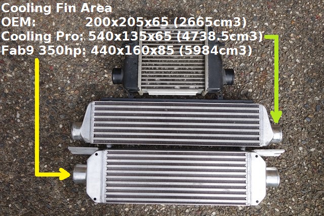
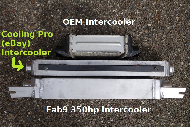
Here's a couple of photos showing the OEM intercooler vs the Cooling Pro (eBay) I had vs the Fab9 350hp intercooler:
Image

Image

Note that the Fab9 hose barbs are higher than the OEM and Cooling Pro intercooler barbs - more on this below.

Tha Fab9 intercooler has 6mm thick integrated mounting brackets that allow it to be bolted to the tiedown hook's frontmost boltpoints.
This is great since it makes for a solid mounting but unfortunately that's also where I mount my toe hook so I'm going to have to get some longer bolts and fabricate a 6mm shim that allows the tow hook to be mounted on top of the Fab9 mount point.

I made some rubber pads to fit between the intercooler's brackets and car and it fitted beautifully, no need to bend anything out of the way.

The intercooler barbs were now presenting me with problems:

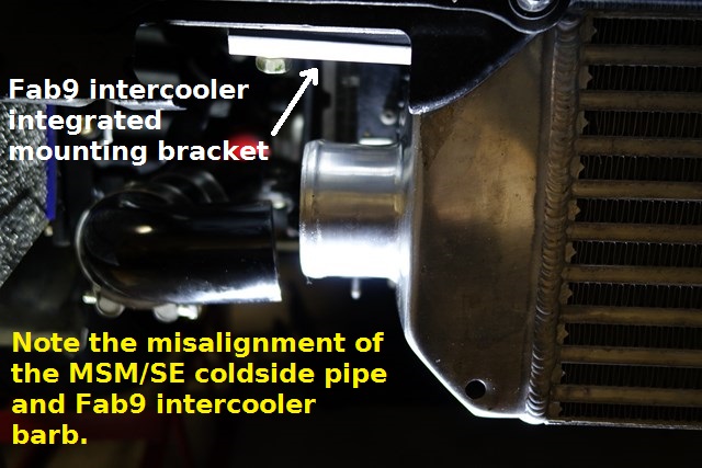
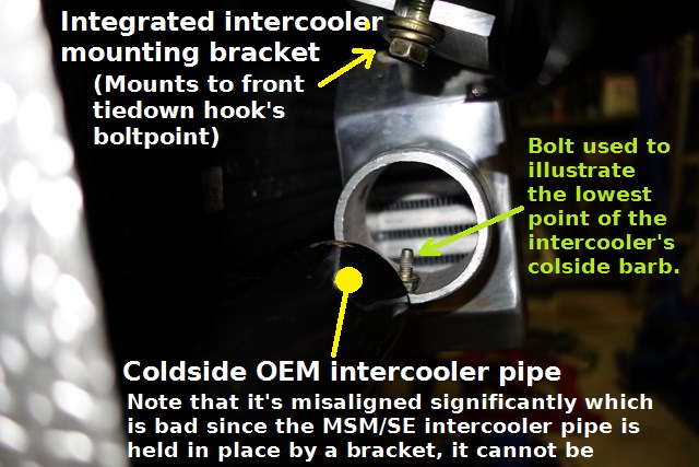
I had NitroDann make me a low-route intercooler hotside pipe when he installed by EFR6250 turbo. It's pretty tight down there, even for a 2" pipe/hose, and with the slightly higher location of the barbs, now there's only a couple of mm between the pipe and front bolt of the passenger-side sway bar - they're going to knock together when driving :(

The coldside was even worse. On the MSM/SE, the coldside intercooler pipe is mounted using a very solid bracket so there's almost no flexibility in it. Because the Fab9 barbs sit higher, there's a very serious misalignment:
Image

Image


For the hotside I've decided to remain with 2" pipes/hoses due to the limited space. I've ordered a 30* silicone angle joiner (to connect to the compressor outlet - it needs a bend) and a metre of 2" straight silicone hose. I plan to cut down Dann's hotside intercooler pipe but the majority of the hotside will be the 1m 2" straight silicone hose - it will be fitted so that it bows downward enough to comfortably clear the sway bar.

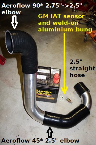
For the coldside I've decided to switch to 2.5" pipes/hoses since my Skunk2 throttle body requires a 2.75" hose connector and I can find a 2.75->2.5" silicone reducing 90* elbow but not a 2.75"->2" version.
Going from the intercooler's 2.5" barb down to existing 2" hoses, back up to 2.5" hoses, then up to the Skunk2's 2.75" hose is just silly, especially when I need to buy new hoses/pipes anyway.
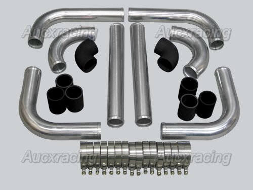
I've bought a generic 2.5" intercooler pipe+hose joiner kit which will give me plenty of options that I'll need to route the coldside air.

Oh well, might get it finished next weekend.


Originally posted by Lokiel, Sat May 24, 2014 9:38 pm[

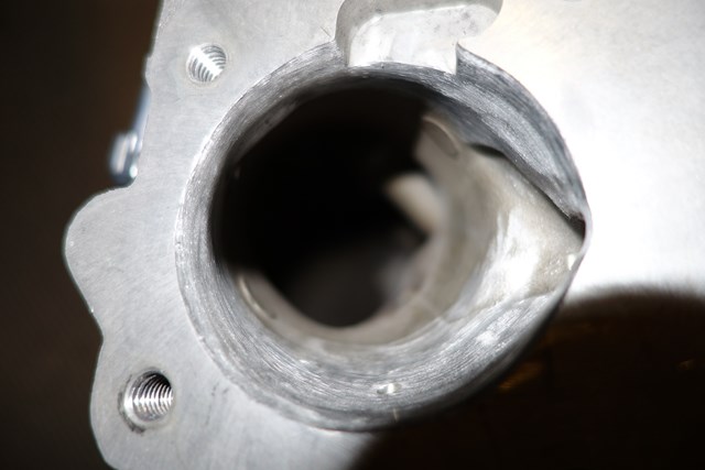
I still had some time in the day so decided to port my SquareTop intake manifold's 55mm ID to match my Skunk2 throttle body's 64mm ID.

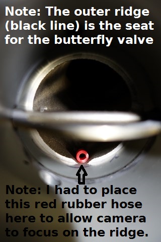
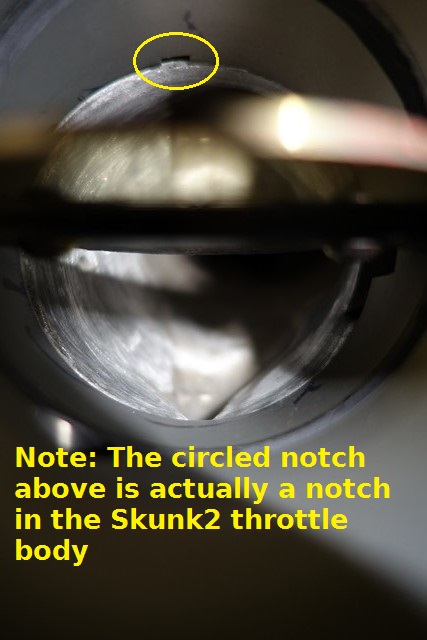
Here's what the inside of the mounted Skunk2 throttle looks like if left un-ported:
Image

You can see that there's quite a lip on the manifold which will impact airflow - air likes to flow along walls so when it hits the lip it will generate quite a lot of turbulence.

Based on my past experience, I knew that you CANNOT grind aluminium with stone wheels, the aluminium just melts onto the surface of the stone and renders it useless.
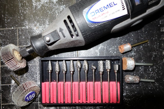
I'd previously ordered a "10x Solid Carbide Burrs For Dremel Rotary Tool Drill Die Grinder Carving Bit" kit from eBay seller 99ua and some 160 and 180 flapper wheels for this job which arrived during the week and they're perfect for small jobs like these using the Dremel:
Image

- those 3 grinding stones on the right are from previous attempts at grinding aluminium and illustrate why they shouldn't be used.

I was a bit worried about using the carbide bits, fearing that they'd really chew through the aluminium and leave it full of divots if I wasn't careful but this was unfounded.
Using the Dremel running at 80% max with circular strokes allowed for a lot of control and it took longer than I would have thought - slow and steady is what you need for this type of work though.

After many, many, many iterations of grinding and fitting the Skunk2 throttle body to check my progress, I've finished the initial grind:
Image

Image


For good measure, I also ground the casting joins smooth on the 4 cylinder holes and plan to finish the porting by smoothing it with a bit more work and the Dremel flapper wheels.


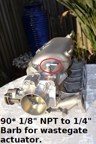
I REALLY didn't like the blue 90* 1/8" NPT to 1/4" barb on top of the manifold so replaced it with a colour-coordinated silver version - much better:

Before:
Image


After:
Image


Originally posted by Nevyn72, Sat May 24, 2014 10:35 pm[

Wow, go for an improvement in intercooler performance, get a whole lot of headaches! :?

Do you think the Fab9 intercooler will perform that much better than the cooling pro one you were using previously?

Looking at the pictures the Fab9 is narrower but taller, now the Cooling Pro already has about 25% of it's exposed surface below the direct air path through the opening in the front bumper (I know I've got one) but doesn't fill the entire available width.
Given the Fab9 will use even less of the available direct airflow from a width perspective, and have more obscured from a height perspective, is it going to be able to perform better?
Now I can't comment on how the air will flow once it passes through the opening in the front bumper, however on the face of it, the Fab9 will 'present' less of it's face to the direct airflow so the only real benefit it will get is from it's ~30% increase in thickness, to be counterbalanced by reduced 'facing' surface area.

Now this might be all bumpf as the Cooling Pro sits slightly lower than is ideal so if the Fab9 is mounted slightly higher then the situation is quite different.... Do you have a picture of how it sits relative to the opening in the bumper or haven't you re-fitted the bumper yet?

I'm just curious as to whether the Fab9 is going to offer the sort of increased performance required to justify the aggravation in fitting it.......


Originally posted by Okibi, Sun May 25, 2014 2:28 am[

Great write up, was spewin' I missed that flat top manifold. I've never noticed that notch in the first runner before, does it continue on the inside?
Don't worry about dying, worry about not living!
Garage Thread: http://www.mx5cartalk.com/forum/viewtopic.php?f=57&t=76716

User avatar
Lokiel
Forum legend
Posts: 4126
Joined: Thu May 28, 2009 2:39 pm
Vehicle: NB SE
Location: Brisbania

Re: Lokiel's "Gina" (once a 2004 Titanium SE) Recreated AGAIN

Postby Lokiel » Tue Jun 05, 2018 8:12 pm

Originally posted by Lokiel, Sun Sep 24, 2017 4:42 pm

Originally posted by Lokiel, Sun May 25, 2014 12:26 pm[

Nevyn72 wrote:Wow, go for an improvement in intercooler performance, get a whole lot of headaches! :?

Do you think the Fab9 intercooler will perform that much better than the cooling pro one you were using previously?

Looking at the pictures the Fab9 is narrower but taller, now the Cooling Pro already has about 25% of it's exposed surface below the direct air path through the opening in the front bumper (I know I've got one) but doesn't fill the entire available width.
Given the Fab9 will use even less of the available direct airflow from a width perspective, and have more obscured from a height perspective, is it going to be able to perform better?
Now I can't comment on how the air will flow once it passes through the opening in the front bumper, however on the face of it, the Fab9 will 'present' less of it's face to the direct airflow so the only real benefit it will get is from it's ~30% increase in thickness, to be counterbalanced by reduced 'facing' surface area.

Now this might be all bumpf as the Cooling Pro sits slightly lower than is ideal so if the Fab9 is mounted slightly higher then the situation is quite different.... Do you have a picture of how it sits relative to the opening in the bumper or haven't you re-fitted the bumper yet?

I'm just curious as to whether the Fab9 is going to offer the sort of increased performance required to justify the aggravation in fitting it.......


"The more challenging the journey, the greater the satisfaction upon completion!" - that's what I keep telling myself when this crap happens otherwise I'd never do anything - but it's nice when things are easy too!

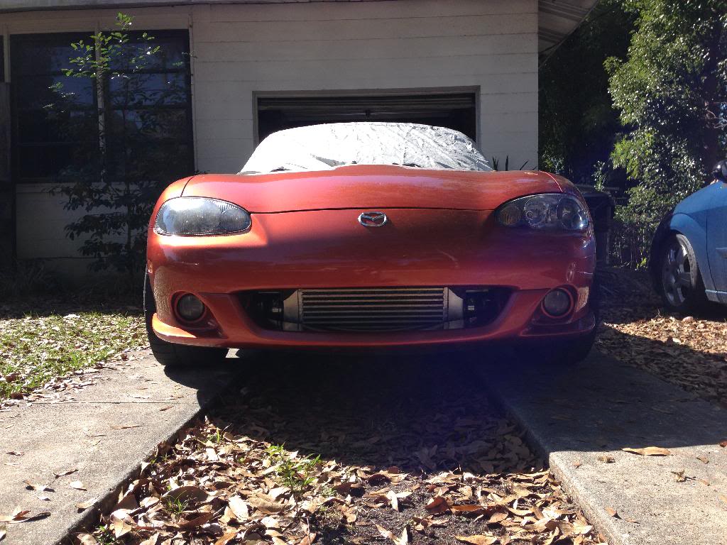
Here's a photo of how it looks installed on a Lava Orange MSM from the US:
Image

As you can see, there's a lot more "face" exposed directly to incoming air so I don't doubt that its getting more airflow through it.

I was advised by several people that the CoolingPro intercooler would need to be upgraded if I plan to track the car at 280+rwhp so it was something that I'd have to do eventually anyway.

I must admit I'm annoyed that I couldn't fit the coldside pipe (I half expected issues with the hotside due to clearance issues) and that really explains why you can find lots of pictures of the Fab9 intercooler mounted with NO pipes attached, some with the hotside attached, but none with the coldside attached.
This is why I prefer it when people include this sort of stuff in their build/install threads, it allows others to be prepared for it - now I have to wait around for parts to arrive before I can complete it :(

Non-MSM/SE readers are probably thinking "[b]Suck it up Princess![/b]" since they have to figure out the intercooler piping themselves whereas MSM/SE owners have it already in place from the factory and can easily modify it to fit the CoolingPro intercooler.

The Skunk2 throttle body meant that I'd need to modify the coldside intercooler piping anyway so I can't complain too much and having transitions from 2" then up to 2.5", down to 2", up to 2.5", then to 2.75" must screw up airflow (especially that 2.5" down to 2" transition). With my new intended setup, it will just be 2"->2.5"->2.75" which is unavoidable (compressor outlet is 2", intercooler barbs are 2.5" and Skunk2 throttle body is 2.75").

FYI: I contacted FM about their molded silicone hoses and am also considering that option since it's a lot tidier because it requires fewer clamps and joiners.
Apparently they're re-designing the coldside hose so that it's all one integrated unit and will have it available in the next few weeks.
I've asked for details (eg. hose-end sizes and what barbs are going to be integrated into it, such as BOV, AIT sensor and EBC/MBC boost level).
If enough people are interested I'd like to coordinate a mini-Group Buy to save on S&H.
They do sell components individually so you can purchase just the hot-side or cold-side.
I'm planning on just purchasing the hoses to keep costs down since we can purchase the clamps here.
Send me a PM if you're interested and I'll keep you up to date.


Originally posted by Nevyn72, Sun May 25, 2014 12:56 pm[

Lokiel wrote:Here's a photo of how it looks installed on a Lava Orange MSM from the US:

Image


As you can see, there's a lot more "face" exposed directly to incoming air so I don't doubt that its getting more airflow through it.

Must admit I'm still not convinced, from that shot above, while it appears to be mounted slightly higher, there appears to be a good 1/3rd of the intercooler 'hiding' below the bottom of the opening in the front bumper.....

For comparison here's what the Cooling Pro looks like in my car.

Image

I would say the 'fill factor' for want of a better term is roughly the same, possibly slightly more for the Cooling Pro.... However the Fab9 unit is 30% thicker so you should get additional cooling as a result of that. :wink:

uncited wrote:FYI: I contacted FM about their molded silicone hoses and am also considering that option since it's a lot tidier because it requires fewer clamps and joiners.
Apparently they're re-designing the coldside hose so that it's all one integrated unit and will have it available in the next few weeks.
I've asked for details (eg. hose-end sizes and what barbs are going to be integrated into it, such as BOV, AIT sensor and EBC/MBC boost level).

Does this integrated silicone tube also replace the FM metal intake elbow?
If not wouldn't most of those barbs still be there on the elbow?


Originally posted by Lokiel, Sun May 25, 2014 1:50 pm[

Nevyn72 wrote:Does this integrated silicone tube also replace the FM metal intake elbow?
If not wouldn't most of those barbs still be there on the elbow?


Yes, the new integrated silicone tube replaces the FM MSM throttle body elbow, all the way to the intercooler outlet.

You can see the current version here on the left that comprises of 3 sections, intercooler hose, pipe to house BOV, and throttle body elbow:
Image
http://flyinmiata.com/index.php?deptid=&parentid=&stocknumber=22-50305%20%201990-93
- since I need a 2.75" connection to the the Skunk2 throttle body, the current version may be a better option for me?

This is the hotside hose (US$113.95):
Image
http://flyinmiata.com/index.php?deptid=&parentid=&stocknumber=22-50100
- I'll need to modify it a bit to connect to the 2" EFR6258's compressor outlet which is between 4 and 5 o'clock but it may prove to be the most elegant option.


Originally posted by Magpie, Sun May 25, 2014 4:19 pm[

So what is the plan for the part of the inter cooler below the mouth?


Originally posted by Nevyn72, Sun May 25, 2014 4:33 pm[

Magpie wrote:So what is the plan for the part of the inter cooler below the mouth?

If you look carefully at the two images in my post above you can see what they do in the US.....

The bottom of the opening on my car is horizontal, the Lava Orange one from the US dips downward.
Mine is how it comes from the factory and isn't a problem in OEM circumstances because unlike the Cooling Pro, Fab9 and other aftermarket options the factory intercooler is mounted a little higher.

The US one has had what they call "the heat gun mod" where they heat up the lower edge of the opening in the front bumper and bend it down slightly to make that part of the opening wider. However without also increasing the size of the front part of the opening I'm not really sure if this will make that much difference. Maybe simply exposing more of the front of the intercooler to direct airflow does, who knows? :|


Originally posted by Lokiel, Sun May 25, 2014 8:40 pm[

Okibi wrote::
I've never noticed that notch in the first runner before, does it continue on the inside?


I wanted to answer this question with photos so had to wait until I got home to take some photos.

The notch on the first runner is to accomodate the front throttle cable bracket:
Image

- it's not present on the VTCS manifold, the bracket sits vertically and is comfortably in front of the the front runner.

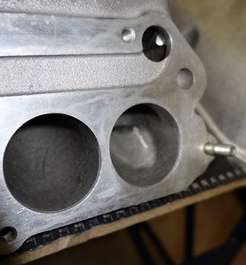
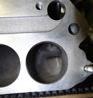
Here's the inside of the front runner:
Image

Image

- as you can see, it's nowhere near as big as you'd expect based on the sizeable chunk missing on the outside, and no, I'm NOT planning on making it any smaller.


Originally posted by Okibi, Sun May 25, 2014 10:40 pm[

Thanks! :mrgreen:
Don't worry about dying, worry about not living!
Garage Thread: http://www.mx5cartalk.com/forum/viewtopic.php?f=57&t=76716

User avatar
Lokiel
Forum legend
Posts: 4126
Joined: Thu May 28, 2009 2:39 pm
Vehicle: NB SE
Location: Brisbania

Re: Lokiel's "Gina" (once a 2004 Titanium SE) Recreated AGAIN

Postby Lokiel » Tue Jun 05, 2018 8:13 pm

Originally posted by Lokiel, Sun Sep 24, 2017 4:43 pm

Originally posted by Lokiel, Sun Jun 01, 2014 7:55 pm[

This weekend's BIG job was to install the Squaretop intake manifold, ID725cc injectors and Skunk2 throttle body, and possibly fit the Fab9 COPs.

The intake manifold still required some finishing.

There's 6 casting "bumps" on the interior of the manifold, two in the inlet, two on the base, and two on the roof - the ones on the roof cannot be reached so I left those.

Here's one on the bottom between runners 1&2, it was too hard to reach so I left it alone:
Image


Here's one on the inlet, partially ground to highlight it (I deleted both of these in the inlet):
Image


Here's the rear bottom one deleted ("ellipsed" in black) and some additional porting work done on the rear of the manifold to eliminate the pronounced bump exiting the last runner ("ellipsed" in yellow):
Image


I was going to use Dremel flapper wheels to finish the porting but was warned by '95MSM from mazda-speed.com NOT to do this since FM found that the material from the flapper wheels would disperse through the manifold and lodge into its pits, eventually dislodging and damaging pistons when they worked their way through to the cylinder.

I bought a Dremel carbide fine grinding bit and used that for the final finishing - not "polish-finished" but not too bad and no worse that the original cast finish:
Image


After this, I sprayed the bejesus out of the manifold using a hose and set it aside to dry out until Sunday.

More to come...


Originally posted by pezchops, Sun Jun 01, 2014 8:09 pm[

at my work we do a lot of polishing and blending with aluminium machined parts.
rather than flapper wheels we use a mounted `scotch brite` wheel that is not agressive and the wheel residue will wash out easily.
but then i have heard it is possible to over work surfaces,some turbulance is good??
Don't worry about dying, worry about not living!
Garage Thread: http://www.mx5cartalk.com/forum/viewtopic.php?f=57&t=76716

User avatar
Lokiel
Forum legend
Posts: 4126
Joined: Thu May 28, 2009 2:39 pm
Vehicle: NB SE
Location: Brisbania

Re: Lokiel's "Gina" (once a 2004 Titanium SE) Recreated AGAIN

Postby Lokiel » Tue Jun 05, 2018 8:13 pm

Originally posted by Lokiel, Sun Sep 24, 2017 4:44 pm

Originally posted by Lokiel, Sun Jun 01, 2014 8:49 pm[

I'd spent a few days trying to find as much info as I could about removing the lower half of the intake manifold since I knew that it was going to be tough - there are 9x12mm nuts connecting the manifold to the engine block, 5 on top and 4 below each runner.

There's also a 10mm nut that hold a fuel-line bracket that needs to be removed to access the 2nd runner's nut.

Accessing these lower nuts and bolts is all done by feel and it's a real bitch of a job, you really need a 10 year old kid to do it and lots of socket combinations. The cast manifold will also inflict multiple cuts on your fingers, hands and arms too. If that's not bad enough, the MSM/SE has some fuel-line "spaghetti" mounted on a solid bracket that makes accessing the 2nd and 3rd runner nuts even harder - in hindsight, I should have unbolted the bracket.

Here's the socket combination I needed to crack the lower rear two manifold nuts just to get at them and be able fit the ratchet so that I could turn it (the front 2 weren't as convoluted):
Image

Luckily, once cracked, the nuts are easy to remove by hand.

That was a bugger of a job but worse was knowing that I'd have similar issues putting the new one on.

The Injector Dynamics 725cc injectors use USCAR connectors rather than the stock DENSO-style connectors.
I didn't want to use the DENSO->USCAR adapters I had since the additional plug and socket per injector is too bulky so I cut up the harness and adapters to make it neater/simpler (see top green "ellipses"):
Image


The shelf, "ellipsed" in yellow in the photo above, is where I planned to mount the Fab9 COP 4xchannel ignition coil driver since this is one of the few places available in the MSM/SE. The coil driver has a metal plate on its underside so should be mounted on a metal surface to act as a heatsink for it.

Unfortunately the pre-made MSM/SE Fab9 COP harness is too short to reach the shelf and I'd had enough of harness modding by this time so I've decided to put off installing the Fab9 COPs until next weekend.

At this stage I'm planning on mounting it horizontally behind the rear of the engine using a DIY aluminium L-bracket/shelf bolted to the OEM Narrowband O2 harness mount point (this is now vacant since I no longer have a Narrowband O2 sensor).


Originally I planned to use an EGR blockoff plate for the EGR valve since it's no longer used but unfortunately the OEM MSM/SE harness only has a short length to connect to the EGR valve so it cannot be tucked away easily like the now redundant VTCS solenoid harness plug (highlighted with yellow dots in the 2nd photo below):
Image


Image

Other than removing the EGR plug from the harness, since it's so short, there was no hiding it so I decided to sandwich the EGR blockoff plate between the manifold and EGR valve so I can plug the short EGR socket into it - if nothing else, at least it looks legit!
I taped up the end of the now redundant longer VTCS socket and tucked it between the two halves of the intake manifold so it cannot be seen and is completely out of the way.

Getting those lower manifold nuts "started" on the studs was going to be tough without dropping/losing the nuts. I used a long socket and a magnetic socket insert to ensure that this wouldn't happen:
Image

- no need to use those two "magnetic fishing rods" with these inserts.

Here's the ID725cc injectors in their new "home" - I figured I'd show them now since it's the last time I'll see them for a long while (I hope):
Image


So here it is all assembled, complete with Skunk2 throttle body:
Image


Image


Image


One "gotcha" I hadn't expected was that the Skunk2 throttle body isn't watercooled like the OEM throttle body so I need to buy an 8mm hose-joiner to connect the inlet and outlet hoses:
Image


Hopefully this week the rest of my intercooler hoses will arrive so I can complete the intercooler install.


Originally posted by Magpie, Sun Jun 01, 2014 9:03 pm[

ITB's would have been easier :)


Originally posted by Lokiel, Sun Jun 01, 2014 10:20 pm[

Magpie wrote:ITB's would have been easier :)


I doubt it, I read your thread regularly :P


Originally posted by Nevyn72, Mon Jun 02, 2014 8:16 am[

Looking very good there mate! :mrgreen:
It's going to be one very clean and tidy engine bay when you're all done. :wink:

In a way it's a bit of a shame this is so soon after you had the engine up and running and you never had the full tune done..... It would have been interesting to see how much of a difference the throttle body + manifold would have made compared to stock as it's a lot of work and a significant investment.
Where would you be expecting the biggest gains from these two? Is it more for the top end of the rev range or are there other benefits?

Will this mean you have to start the base tune from scratch with the Adaptronic? :|

What injectors were you using before the ID725's?


Originally posted by sailaholic, Mon Jun 02, 2014 9:19 am[

The water is to heat the air I believe not cool it for better idle etc when it's cold.


Originally posted by Roadrunner, Mon Jun 02, 2014 9:34 am[

sailaholic wrote:The water is to heat the air I believe not cool it for better idle etc when it's cold.


I often wondered what the purpose of it being routed through the throttle body was for. Googling came up empty.

That engine bay is looking super neat too. Making me jealous


Originally posted by Lokiel, Mon Jun 02, 2014 11:54 am[

sailaholic wrote:The water is to heat the air I believe not cool it for better idle etc when it's cold.

Thanks for that tid-bit of information, I never knew that and, like Roadrunner, couldn't find out via Google any information about it so just assumed it was for cooling the throttle body - how completely wrong was that! It does make sense though and shouldn't present any problems here in Brissie :P


Nevyn72 wrote:Looking very good there mate! :mrgreen:
It's going to be one very clean and tidy engine bay when you're all done. :wink:

In a way it's a bit of a shame this is so soon after you had the engine up and running and you never had the full tune done..... It would have been interesting to see how much of a difference the throttle body + manifold would have made compared to stock as it's a lot of work and a significant investment.
Where would you be expecting the biggest gains from these two? Is it more for the top end of the rev range or are there other benefits?

Will this mean you have to start the base tune from scratch with the Adaptronic? :|

What injectors were you using before the ID725's?


Here's the Flat-top/Square-top "Product Description" from the miataroadster site:

"This is the highly sought-after JDM and European market intake manifold with neither of the flow-obstructing VICS or VTCS butterflies located in the runners on 1999-2000 and 2001-2005 US-spec manifolds.
Dyno testing has proven this manifold to provide superior performance for both naturally aspirated and forced induction applications."

After removing the VTCS system during the engine rebuild I wasn't happy with all the extraneous VTCS barbs hanging off the manifold which needed to be plugged (or looped to each other, like the loopback hose on the VTCS solenoid shown above) and the VTCS solenoid hanging off the back of the manifold which would look obvious if removed. The squaretop has none of that so it wont be obvious that the VTCS has been removed, or was ever present.

I also removed the now-redundant EGR boost sensor, EGR boost sensor solenoid valve, purge solenoid valve and VTCS vacuum switch "cluster" that you can see on the left hand side of the front strut brace (mounted on the bronzed bracket) in this old photo:
Image

This really tidies that section up too. The engine bay is now looking much tidier - the VTCS really is massively convoluted.

As far as performance goes, the squaretop should improve the top end.

After the engine rebuild, which was a MAJOR dent in the wallet, I originally planned to install the 725cc injectors, Fab9 COPs and Fab9 350hp intercooler before getting a professional tune so as not to waste money on an interim tune. Fortunately (or should that be "unfortunately"), a squaretop became available and I'd had my eye on these for a few years so I snapped it up and bought the Skunk2 throttle body for it and decided to install those too before getting the professional tune. So yes, it would have been nice to get before and after squaretop dyno data but after the engine rebuild I've decided to reign in the spending (not working too well so far), continue to DIY as much as possible to save $$$ and learn more (that's my nature anyway) so will complete these jobs before getting the professional tune. I've promised myself [b]NO MORE UPGRADES[/b] until these are complete and the professional tune is completed though.

These modz will require a complete basic re-tune for Idle control and running since the injectors were upgraded from Deatschwerks 600c injectors to Injector Dynamics 725cc injectors, the throttle body has changed (requires idle screw adjustment) and hopefully the airflow has improved. I'm getting pretty efficient at Idle tuning now so it should only take an afternoon.


Originally posted by Magpie, Mon Jun 02, 2014 12:48 pm[

I'm glad you limited your "NO MORE UPGRADES" statement. Mods are like drugs, easy to get hooked on but difficult to kick the habit.

I do like the attention to detail that you have done with your build, this is something that I'm starting to do only now, the little things that make it neater.
Don't worry about dying, worry about not living!
Garage Thread: http://www.mx5cartalk.com/forum/viewtopic.php?f=57&t=76716

User avatar
Lokiel
Forum legend
Posts: 4126
Joined: Thu May 28, 2009 2:39 pm
Vehicle: NB SE
Location: Brisbania

Re: Lokiel's "Gina" (once a 2004 Titanium SE) Recreated AGAIN

Postby Lokiel » Tue Jun 05, 2018 8:13 pm

Originally posted by Lokiel, Sun Sep 24, 2017 4:46 pm

Originally posted by Lokiel, Mon Jun 02, 2014 2:27 pm[

Does anybody know what those 3 mount holes below the smaller EGR block-off plate are/were for?

Image


I've scoured the manual and can't find anything and Google hasn't helped. Nothing seems to be unplugged/unattached in the engine bay so maybe there was something plugged in before the engine rebuild that has now been removed?

- this type of thing worries me, it's like assembling something and have a couple of screws left over.


Originally posted by Nevyn72, Mon Jun 02, 2014 4:00 pm[

Lokiel wrote:Does anybody know what those 3 mount holes below the smaller EGR block-off plate are/were for?

I just had a look at mine, which so far as I know hasn't been touched since it left the factory in that area, and there's nothing actually bolted on there. :wink:

Maybe it was meant to mount something on that side of the car for left hand drive markets?


Originally posted by Lokiel, Mon Jun 02, 2014 4:58 pm[

Thanks for that confirmation, one less thing to lose sleep over.

During lunch I trolled through a Google image search on Miata/MX5 intake manifolds and engines and either couldn't see those mount points at all or none had anything attached to them.

I suspect you're correct, they were probably to mount something required for other markets but not here.


Originally posted by Okibi, Mon Jun 02, 2014 6:17 pm[

Nothing on mine either


Originally posted by timk, Mon Jun 02, 2014 6:23 pm[

No more fiddling until you are consistently running sub minute Clubman and Lakeside! :P


Originally posted by Lokiel, Mon Jun 02, 2014 6:29 pm[

But I need all the help I can get! Seriously though, I'm dying to "get back on track" since there's no substitute for experience.


Originally posted by ManiacLachy, Wed Jun 04, 2014 11:08 am[

Lokiel wrote:The coldside was even worse. On the MSM/SE, the coldside intercooler pipe is mounted using a very solid bracket so there's almost no flexibility in it. Because the Fab9 barbs sit higher, there's a very serious misalignment:
Image

Image


Did you manage to resolve the coldside misalignment yet? I'm curious how it turned out :?:


Originally posted by Magpie, Wed Jun 04, 2014 12:26 pm[

Lokiel once you are happy with your progress you will get on to the track again. Once you get on the track you will find other areas the need modification. It is a journey, your journey, so enjoy it. Your build thread will help others make informed decisions.

It would be good to see you at Jap Nats 2015, the more MX5's there the better :)


Originally posted by Lokiel, Thu Jun 05, 2014 11:35 pm[

ManiacLachy wrote::
Did you manage to resolve the coldside misalignment yet? I'm curious how it turned out :?:

I bought an eBay 2.5" intercooler kit from AUCXRcing since I wanted as many options as possible:
Image

The hose joiners aren't as thick as Aeroflow hoses so I probably wont use them.
The clamps don't have rolled edges like the more expensive ones but they're definitely better than worm clamps and I plan to use them.

A 45* pipe would have been nice to have too but in the end the only pipes I needed from this kit were a J-elbow and a short 90* elbow.
I ended up cutting the short 90* elbow 4 times, removing about 10mm each time from one end until I was happy with the bend (using a hacksaw only to keep the noise down in my townhouse complex) so that end will need bead rolling.
I also needed an Aeroflow 90* 2.75"->2.5" hose reducer elbow for the Skunk2 throttle body and an Aeroflow 45* 2.5" elbow to connect the two pipes. I needed to shorten the 2.75" hose leg to the TB to ensure that the elbow didn't hit the fan bracket attached to the radiator:
Image


I still need to get the aluminium weld-on barb, shown above, welded onto the pipe just below the top elbow for the IAT sensor as well as a boost hose barb, not shown since I'm still waiting for that, for the EBC.

When the ends are clamped onto the intercooler and Skunk2 throttle body, the hoses/pipes don't move much at all and easily clear the sway bar and everything else so at this point I'm not planning on adding any additional bracing (unless advised otherwise).


The hot-side plumbing now needs to be addressed to stop it touching the front passenger-side swaybar bolt.

I cut Dann's custom pipe but couldn't make it fit with what I already have so I've ordered a couple of Aeroflow 2" elbow hoses, a 45* and a 90*, and a 45* 2" aluminium pipe which I'm hoping will arrive tomorrow so that I can finish the hot-side on the weekend.

The much longer-ended Aeroflow 90* elbow will replace the current short rubber one I have connected to the turbo outlet since it's almost impossible to insert the 2" pipe into it - I really don't know how Dann managed to fit his custom intercooler pipe since it's incredibly tight on that side.

It really pays to have lots of options available when doing intercooler plumbing and ideally you want as few hose joiners as possible.


PS: I DON'T work for Aeroflow but do like their hoses (much sturdier than ASI or TOG) and fittings (cheaper than Speedflow and I see little difference between them).


Originally posted by NitroDann, Fri Jun 06, 2014 1:12 am[

I'll preface this by saying that Lokiel doesn't know this.

I am an aeroflow dealer too.

So I get 5 points for the intercooler pipe job and another 5 for aeroflow.

What do in owe you for that accidental plug Lokiel? 8)

Dann


Originally posted by ManiacLachy, Fri Jun 06, 2014 8:20 am[

Man, that's alot of work for something that you expect to bolt straight on! I had the Fab9 Intercooler on my wish list, now I'm not so sure.

What did you do with the Cooling Pro?


Originally posted by Magpie, Fri Jun 06, 2014 9:07 am[

Lokiel I'm sure you remember Charlie's issues when some of his connections were constantly 'blowing' apart, however you may not be intending of running Charlie's level of boost. But, less connections equals less risk.

When do you plan to be back on the road testing/tuning?


Originally posted by Lokiel, Fri Jun 06, 2014 10:37 am[

ManiacLachy wrote:Man, that's alot of work for something that you expect to bolt straight on! I had the Fab9 Intercooler on my wish list, now I'm not so sure.

What did you do with the Cooling Pro?


CoolingPro intercooler, MX5Mania bracket and CoolingPro 2.5"->2" hose reducers sold to monty007.

I've now got quite a collection of hoses/pipes/brackets but you can see now that I've done it, there's really not that much required.

It's actually a good idea to replace your MSM/SE OEM intercooler plumbing anyway since its cast iron rather than stainless steel or aluminium and the cold-side rusts quite badly (see http://www.mazda-speed.com/forum2/index.php?topic=15428.0 - I'd cleaned mine up previously and have no pictures of how bad it was but the rust was worse than shown in that link, probably because mine had an additional 4 years of rusting). See http://www.mazda-speed.com/forum2/index.php?topic=4044.0 too.

Eliminating the OEM 2" pipe cold-side plumbing can only improve flow too (from the intercooler to the throttle body the OEM transitions are 2.5" -> 2" -> 2.5"; mine now is 2.5"->2.75").

I've added added some suggestions to Bryan too regarding this intercooler at http://www.mazda-speed.com/forum2/index.php/topic,29948.0.html:

ie.

Bryan, can you please consider adding an option to purchase a cold-side plumbing "kit" to go with this intercooler?

A "kit" for the hot-side plumbing is probably not an option due to the fact that turbo configurations will vary (ie. you can't assume that the compressor outlet will be oriented in the same direction) but the cold-side plumbing should be the same for most MX5s since it can adopt the MSM OEM-style routing to the TB.
You could also produce a TB elbow with this kit that incorporates a barb for the IAT sensor and a MBC/EBC boost signal barb.


Originally posted by Lokiel, Fri Jun 06, 2014 10:57 am[

Magpie wrote:Lokiel I'm sure you remember Charlie's issues when some of his connections were constantly 'blowing' apart, however you may not be intending of running Charlie's level of boost. But, less connections equals less risk.

When do you plan to be back on the road testing/tuning?


You mean something like what happens here at 2:44 -> 2:50: <iframe width="560" height="315" src="http://www.youtube.com/embed/iJNaaMJsCHM?rel=0" frameborder="0" allowfullscreen></iframe>

Yes, I'm VERY aware of those issues which is why I intend to bead roll that section of cut pipe. The advantage of the Aeroflow hoses over some other brands is that the legs on their elbows are quite a bit longer which will help them grip the joined pipes (I haven't shortened the hoses at all, I simply slid them further down the shaft) so it's really only the ends that I need to worry about.

You're right in that I don't intend to run "MOST OF IT" as Charlie did but I would like to know what this setup is capable of so I'd like a dyno plot with a "Max Power" run and need to ensure that all connections are tight.

I suspect that I'll only need between 12psi and 15psi to achieve 270-280rwhp which keeps me well within the "track gearbox safety zone" and that should be plenty of power for an MX5 (he said knowing full-well that once that level had been realised that he'd want "[b][b]MOAR POWA![/b][/b]").

I still need to install the Fab9 COPs, including making a bracket for the coil igniter unit, and do the hot-side plumbing, hopefully all the bits will arrive today, and get the barbs welded to the J-pipe. At this stage it looks like it will be next weekend before I can start re-tuning :(


Originally posted by Lokiel, Fri Jun 06, 2014 11:42 am[

After my suggestion to Fab9's Bryan above, he posted in the thread I linked that he'd consider incorporating an AIT bung in the intercooler's cold-side "tank" which is a great idea since it helps prevent heatsoaking the sensor that can occur it it's mounted in the pipe leading up to the TB.

I think I'll get my AIT sensor bung mounted there instead since I haven't done it yet (I can probably get away just threading the 3/8" NPT sensor but I feel more comfortable with a proper barb) - this will require extending the sensor wiring.

Joe Perez (MT.net guru)'s comment #10 here confirms this is a better option too: http://www.miataturbo.net/megasquirt-18/iat-sensor-aluminum-steel-bung-42527/

Edit (Just read this): TSE's Savington post #2 confirms this: http://www.miataturbo.net/megasquirt-18/iat-sensor-intake-manifold-67772/
Don't worry about dying, worry about not living!
Garage Thread: http://www.mx5cartalk.com/forum/viewtopic.php?f=57&t=76716

User avatar
Lokiel
Forum legend
Posts: 4126
Joined: Thu May 28, 2009 2:39 pm
Vehicle: NB SE
Location: Brisbania

Re: Lokiel's "Gina" (once a 2004 Titanium SE) Recreated AGAIN

Postby Lokiel » Tue Jun 05, 2018 8:14 pm

Originally posted by Lokiel, Sun Sep 24, 2017 4:49 pm

Originally posted by Lokiel, Sun Jun 08, 2014 9:57 pm[

I spent most of yesterday trying to figure out my intercooler hotside plumbing, skinning my knuckles, hands and arms trying to get them into places that even the scrawniest Japanese apprentice mechanic would probably struggle with.

I finally got it figured out but still need another 2" 45* hose joiner to complete it. There's a bit of a squeeze on the 45* hose from the compressor outlet where it passes the subframe but that's unavoidable.

I mounted the coldside intercooler piping, which I've named "[b]The Cobra[/b]", but aren't too happy with all the clamps required since there are two per hose joiner:
Image


Does anyone know if there's a place in Brisbane that does custom aluminium Mandrel bending?
"The Cobra" could be used as a template and would allow me to delete two hose clamps on the 45* hose (and the 45* hose).


I spent today installing my Fab9 COPs (see http://fab9tuning.com/index.php?option=com_virtuemart&view=productdetails&virtuemart_product_id=153&virtuemart_category_id=46&Itemid=890&lang=en):
Image

The biggest issue with this kit was figuring out where/how to mount the ignition coil driver and since it came with pre-made harnesses, the length of the harness limited where I could mount it and "I'm over" modifying harnesses for now.

Originally I planned to mount it on the shelf below the brake booster but the harness wouldn't reach it so I decided to make a bracket/shelf attached to the rear of the motor for it. My Carbing 3-point strut brace meant that I couldn't simply bolt it to the top of the firewall, like some others have, and also that I had to ensure that it would fit under the strut brace.

Image

* The bracket was made from 2.5mm aluminum and must also serve as a heatsink for the ignition coil driver, which has a metal plate on its base, so I tried to make it as big as possible.
* It's bolted onto the rear of the engine so to minimise heat transfer, the bracket is sandwiched between rubber pads. I'll switch to silicone washers when I find some.
* The coil driver is bolted onto the bracket using 2x5mm rivnuts and 2x5mm Allen bolts.
* Originally the bracket was rectangular but the wiring on the right hand side looked messy passing over top of the bracket. Since there was enough gap between the bracket and engine block but not enough slack, I cut the curve on the right hand to allow it to be wired through the gap.

Image


Looking tidier now:
Image


Originally posted by Nevyn72, Sun Jun 08, 2014 10:11 pm[

Very nice mate! :mrgreen:
Don't worry about dying, worry about not living!
Garage Thread: http://www.mx5cartalk.com/forum/viewtopic.php?f=57&t=76716

User avatar
Lokiel
Forum legend
Posts: 4126
Joined: Thu May 28, 2009 2:39 pm
Vehicle: NB SE
Location: Brisbania

Re: Lokiel's "Gina" (once a 2004 Titanium SE) Recreated AGAIN

Postby Lokiel » Tue Jun 05, 2018 8:14 pm

Originally posted by Lokiel, Sun Sep 24, 2017 4:50 pm

Originally posted by Lokiel, Wed Jun 11, 2014 10:20 pm[

This arrived yesterday from Fab9:
Image


They had a special on these about a month ago and it was one of those purchases you make after getting home from a night on the turps and decide to do a bit of web surfing because you don't feel like going to bed yet. I'd actually forgotten about it while focusing on the intercooler plumbing and other stuff.

It comes with a new hub bolt and keyway and a custom 4-tooth trigger wheel but I think I'll use a FM 36-2 timing wheel instead to improve timing even more - the Protege 36-1 trigger wheel that timk uses needs to be modified to fit the ATI Super Damper (centre section needs to be cut out) which I'd rather not deal with.

Jason at MX5 Plus didn't think that this was necessary but since the engine will produce more power and is sitting on competition engine mounts I like to think of it as extra insurance - at least that's what I reasoned when I bought it (I think).

I think I'll leave this to be fitted when I get the car tuned professionally though.


Originally posted by Lokiel, Fri Jun 13, 2014 10:55 am[

The final piece of the intercooler hotside "puzzle" arrived yesterday, a 2" 45* silicone hose, so I fitted it last night and cut Dann's 2" custom-pipe up some more to fit:

Image

* The clamps on the 45* hose in the centre haven't been aligned yet.
* I don't plan to shorten that 45* hose at all since it provides additional insurance to prevent the hose blasting off (it was a bitch to slide over the pipes to where it needed to be though - and in the correct orientation).

The routing is now 2.5" Intercooler hotside -> 2.5" to 2" hose reducer -> 90* remnant of Dann's 2" intercoooler pipe -> 2" 45* silicone hose -> 2" 45* aluminium pipe -> cut-down 2" 45* silicone hose (on turbo side) -> 2" compressor outlet.

The following photo shows how tight the 45* hose fits against the subframe (highlighted with the yellow ellipse).

Image

* There's a bit of "hose squeeze" against the subframe so I fitted a protective outer silicone sleeve around it which ironically introduces a little bit more "squeeze". The subframe doesn't move so the hose shouldn't move and wear but I'd rather have the protective sleeve for peace of mind.
* The hose comfortably clears the control arm pivot joint so there'll be no rubbing there.
* I can now get rid of the silicone sleeve on the lower radiator hose, highlighted in green, since the intercooler plumbing now clears that easily.
* The plumbing now comfortably clears the sway bar's mounting bracket too.


I still need to complete the hotside plumbing. The aluminium weld-on 4mm barb I need for my EBC hadn't arrived and I expected it last week at work so I checked Fastway courier's tracking number and saw that it got delivered (and signed for) to Suncorp Group which isn't where it was addressed. They can't even confirm that it was delivered to my building which is pretty pathetic IMO. The e-Bay seller is chasing this up for me now and will resend me a new barb if Fastway can't find it. You gotta love eBay "reps", reputable sellers do go out of their way to keep customers happy and reputations intact - in the "old days" they would have just said "not my problem, I did my bit".
Don't worry about dying, worry about not living!
Garage Thread: http://www.mx5cartalk.com/forum/viewtopic.php?f=57&t=76716


Return to “MX5 Garage Chat”

Who is online

Users browsing this forum: No registered users and 137 guests