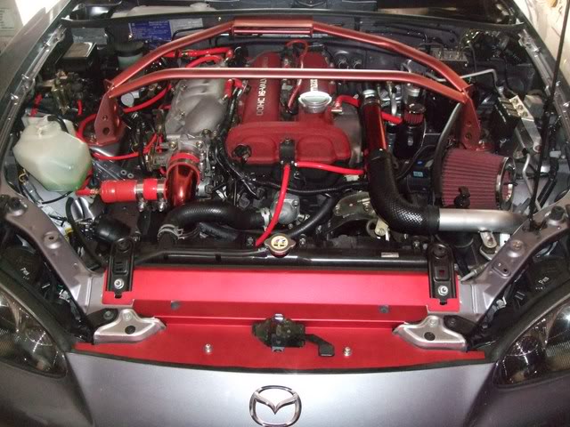
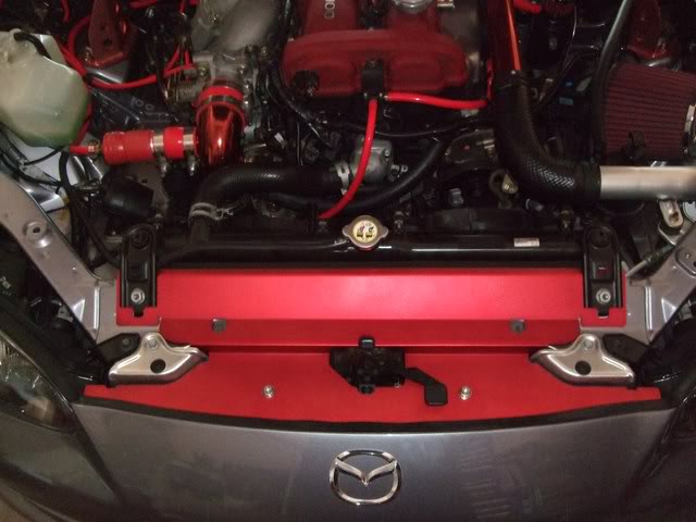
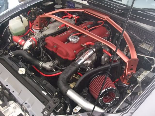
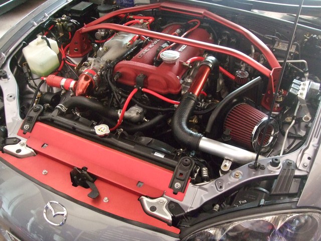
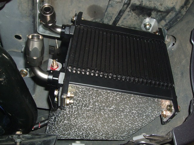
Lokiel's "Gina" (2004 Titanium SE)

Chat to do with your MX5/Miata/Eunos Garage Ride(s).

Moderators: timk, Stu, zombie, Andrew, The American, Lokiel, -alex, miata, StanTheMan, greenMachine, ManiacLachy, Daffy

User avatar
Lokiel
Forum legend
Posts: 4126
Joined: Thu May 28, 2009 2:39 pm
Vehicle: NB SE
Location: Brisbania

Re: Lokiel's "Gina" (once a 2004 Titanium SE) Recreated AGAIN

Postby Lokiel » Tue Jun 05, 2018 7:50 pm

Originally posted by Lokiel, Sun Sep 24, 2017 3:54 pm

Originally posted by Lokiel, Sat Nov 12, 2011 10:26 pm[

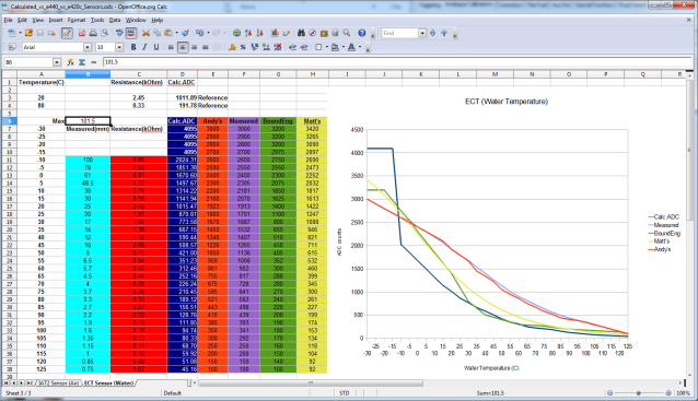
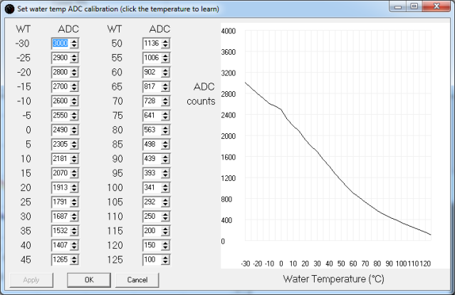
I calibrated the e440 Water temperature today using my newly received KLK-18-840 ECT sensor (I didn't want the hassle of draining the coolant to remove the "hard-to-get-at" ECT sensor) by boiling the sensor and it was bloody damn hot here in Brisbane today without the mandatory shed-fan:

Image


Only the values between 5C..100C are valid, the others I copied from Andy's original base map.

Here's an ECT comparison graph between calculated values (based on the MAZDASPEED tech files' ECT resistance vs temperature calibration and the Adaptronic documentation formula used to translate it to ADC counts), Andy's initial values, my measured values, Boundary Engineering (e420c) values and bitrusty's/Matt's (e420c) Water temperatures:

Image


It's no wonder that when I was using the e420c Water temperature values that my water temperatures went crazy - the radiator thermofans were NEVER activating.

As you can see, they are pretty close to Andy's initial "rough" values.

PS: I got a bit of a surprise when the radiator thermofans activated as the water temperature hit the e440 activation range (86-89C).


Originally posted by Aussie Stig, Sat Nov 12, 2011 11:13 pm[

Novice1 wrote:I know this is a moot point. But I have looked at the back of the decklid with the torque bar and always thought it would look so much better if the torque bar was chromed.

:( Novice1


Basically a sexy tonneau cover!

Interesting because the first thing I saw was the chrome fuel lid stuck out like dogs balls. I would like to see it painted matt black or if you chrome the torque bar it might fit in well. :P


Originally posted by Lokiel, Sat Nov 12, 2011 11:23 pm[

Aussie Stig wrote:
Novice1 wrote:I know this is a moot point. But I have looked at the back of the decklid with the torque bar and always thought it would look so much better if the torque bar was chromed.

:( Novice1


Basically a sexy tonneau cover!

Interesting because the first thing I saw was the chrome fuel lid stuck out like dogs balls. I would like to see it painted matt black or if you chrome the torque bar it might fit in well. :P


Shutup you guys - I've wanted to chrome my roll bar for so long and now I've just come to terms with leaving it black - I don't need you guys screwing with my mind!
(FYI: this was said "tongue in cheek" - but it will screw with my mind :( )


Originally posted by MINX, Sun Nov 13, 2011 7:20 am[

Didnt you say you were going to Chrome Wrap the whole car?


Originally posted by Aussie Stig, Mon Nov 14, 2011 7:24 pm[

Lokiel wrote:
Aussie Stig wrote:
Novice1 wrote:I know this is a moot point. But I have looked at the back of the decklid with the torque bar and always thought it would look so much better if the torque bar was chromed.

:( Novice1


Basically a sexy tonneau cover!

Interesting because the first thing I saw was the chrome fuel lid stuck out like dogs balls. I would like to see it painted matt black or if you chrome the torque bar it might fit in well. :P


Shutup you guys - I've wanted to chrome my roll bar for so long and now I've just come to terms with leaving it black - I don't need you guys screwing with my mind!
(FYI: this was said "tongue in cheek" - but it will screw with my mind :( )


Sorry, but you know it makes sense and would match the fuel cap. 8)
Just wait until you need to take it out for some reason and then get it done. There is no hurry!

Yumm to chrome hoops. :twisted:
Don't worry about dying, worry about not living!
Garage Thread: http://www.mx5cartalk.com/forum/viewtopic.php?f=57&t=76716

User avatar
Lokiel
Forum legend
Posts: 4126
Joined: Thu May 28, 2009 2:39 pm
Vehicle: NB SE
Location: Brisbania

Re: Lokiel's "Gina" (once a 2004 Titanium SE) Recreated AGAIN

Postby Lokiel » Tue Jun 05, 2018 7:50 pm

Originally posted by Lokiel, Sun Sep 24, 2017 3:55 pm

Originally posted by Lokiel, Sat Nov 19, 2011 11:04 pm[

My double garage which housed a single car has now been "invaded" by another car (a black '96 NA8) so a lot of "crap" needed to be thrown out and re-arranged to make space for it.

I purchased a hard top from MX5 Plus about 2 years ago and had it stored on my own DIY stand (a converted Mitre-10 trolley with the pushbar shifted forwards to allow the hard top to balance without toppling the trolley). This worked great except that it took up floor space and was vulnerable to occasionally knocks when it was moved about.

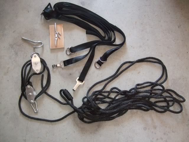
I purchased a hard top hoist (http://www.miatamania.com/Shop/ViewProducts.aspx?PlateIndexID=76709) since I figured this was the safest way to store it, it doesn't take up any space and it makes it easier to fit the hard top on my own.

This is the contents of the kit:
Image


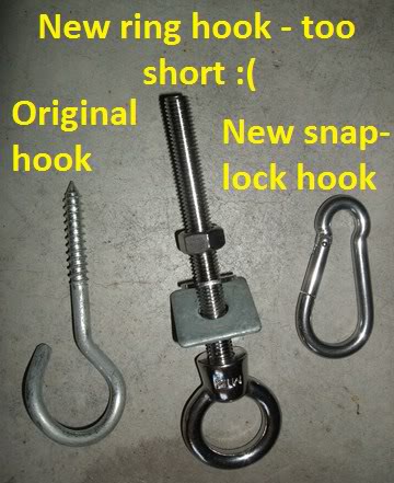
The original snap-lock hook looked too dinky and there's no way I was going to trust the screw-in hook to support the hard top so I purchased some sturdier components:
Image


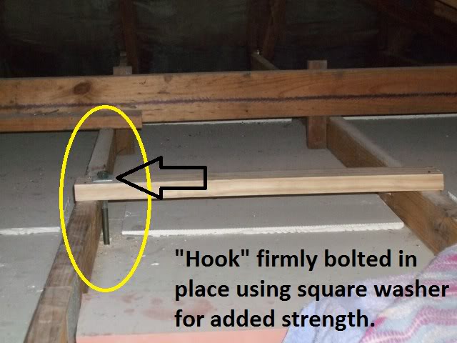
Unfortunately my roof joists were taller than expected so the sexy ring hook was replaced with something more rudimentary:
Image

It was a bloody hot+humid day here in Brisbane and finding myself in a cramped garage roof at sauna-like temperatures had me questioning my sanity and made me realise that I'm not as flexible as I once was.

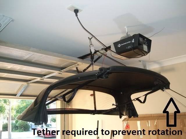
Here's the hardtop mounted on the hoist:
Image

I had to add a single tether to stop the hard top from spinning and it now hangs stationary without swinging, even when there is a mild breeze.
I also added some foam across the front of the hard top to prevent the straps from rubbing; not needed at the rear since it has a rubber bead along the bottom edge.

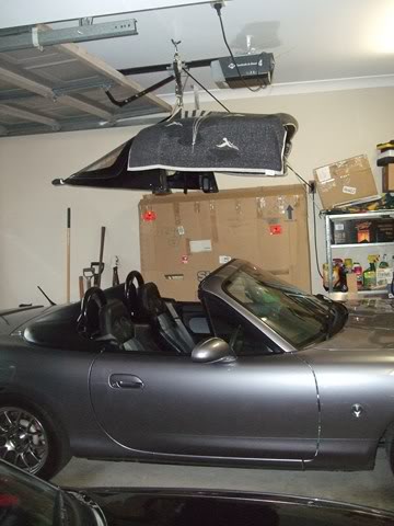
Here's the car under the hard top (with hard top "cover" in place):
Image

When I fit the hard top, I'll need to move the car as far forward as possible. In hindsight, I could have mounted it further back towards the garage door - I was originally worried that the garage door's diagonal brace would contact the hard top.

I've hit my head on the roof once already when getting out of the car but I figure that after I've done this a few more times, I'll learn.


This is a great storage solution for a hard top but I'm not sold on the kit itself. Apart from the hardtop straps/harness, which fit great and have all the adjustability required to secure the hard top to the pulley system, you can get higher quality pulleys and components yourself at Bunnings or any boat shop.
Don't worry about dying, worry about not living!
Garage Thread: http://www.mx5cartalk.com/forum/viewtopic.php?f=57&t=76716

User avatar
Lokiel
Forum legend
Posts: 4126
Joined: Thu May 28, 2009 2:39 pm
Vehicle: NB SE
Location: Brisbania

Re: Lokiel's "Gina" (once a 2004 Titanium SE) Recreated AGAIN

Postby Lokiel » Tue Jun 05, 2018 7:51 pm

Originally posted by Lokiel, Sun Sep 24, 2017 3:55 pm

Originally posted by Lokiel, Sat Nov 26, 2011 4:06 pm[

This week I decided to get my car re-tuned by an Adaptronic specialist tuner to cure its quirky behaviour, particularly with regard to the electrical load issues which caused the rpms to drop drastically at times and its occasional tendency to stall when coming to a stop from speed.

I gave Anthony from Kaizen Garage a call since he's a recommended Adaptronic installer and has been tuning them for over 5 years so knows the intricacies of the Adaptronic and its software. Turns out he only lives 5 minutes away from me and uses the Crossley Street & Race Engineering dyno at Coorporoo which is about 10 minutes away from me.

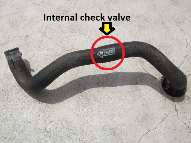
Anthony quickly determined that I was missing the check valve between the brake booster and the intake manifold. I'd earlier replaced the OEM hose with a silicone one and I wasn't even aware that the OEM hose had an internal check valve!

This is where the internal check valve is in an NA OEM brake booster hose:
Image

There was no "TO ENGINE" label on the SE's OEM hose so there was no visible tell-tale sign that it even existed.

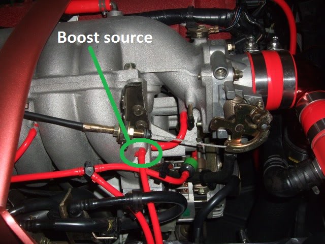
I was originally using the brake booster hose as a read source of boost for my boost gauge and e440 MAP sensor so without a check valve in place, the air volume of the intake manifold was effectively doubled - amazing the car ran as well as what it did; lucky for me I use a lot of engine braking. I'm amazed that GT AUTO garage didn't pick this up when they tuned the car or MIDAS when they installed my Wilwood front brakes!

Anthony's not a fan of using the brake booster hose as a read source of boost because when the one way valve opens under braking, the reported boost levels are completely screwed up. This is more of an issue for aftermarket ECUs or those using EBCs since they react quicker and "go nuts" during this phase.

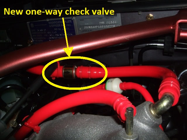
I bought a one-way check valve from Repco and replaced the boost source T-connector tap with it:
Image


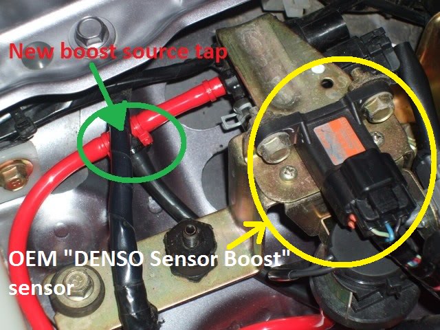
For a boost reading, Anthony suggested tapping the hose that goes to the OEM DENSO "Sensor-Boost" sensor so I moved the T-connector tap to there:
Image

Image


The car runs MUCH smoother now and maxes at 153rwkw which I'm happy with, previously it was 147rwkw - trivial as this difference is, it's nice to crack the 150rwkw barrier on an accurate dyno :P


My aftermarket ECU experience confirms the general rule of thumb regarding aftermarket ECUs, "First find your tuner, then purchase their preferred ECU.". ECU tuning is a cross between "black magic" and an art so you really need a tuner that knows the ECU inside out to get the best out of it.


Originally posted by Aussie Stig, Sat Nov 26, 2011 4:47 pm[

Do you want to post the dyno results and bask in the glow of a good tune?
The fact that it is running better shows that you are on to a good thing. Awaiting further developments....


Originally posted by Lokiel, Sat Nov 26, 2011 5:44 pm[

Yup, will post dyno chart after next tune.

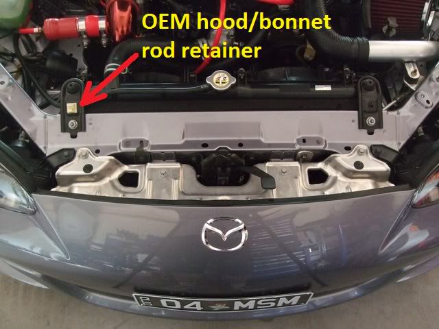
After my radiator coolant boilover, which popped the radiator cap off, I had coolant everywhere in my engine bay which caused the foam filling the gap between the radiator and front of the car chassis to get quite ratty. I thought that the Beatrush Radiator Cooling Panel might help fill this gap instead.

Here's the BEFORE photo:

Image


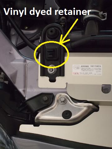
Since I had to remove the two black radiator mounting brackets, I figured that I may as well "fix" that horrible/cheap white OEM bonnet rod retainer with black vinyl dye.

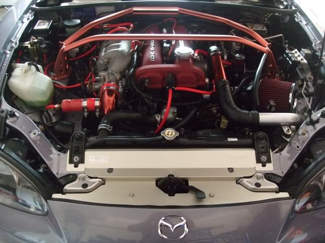
Here's the AFTER photos:

Image

Image


There is still a small gap between the radiator and the panel so the original foam under the panel is still needed so I think I'll replace the foam with rubber.

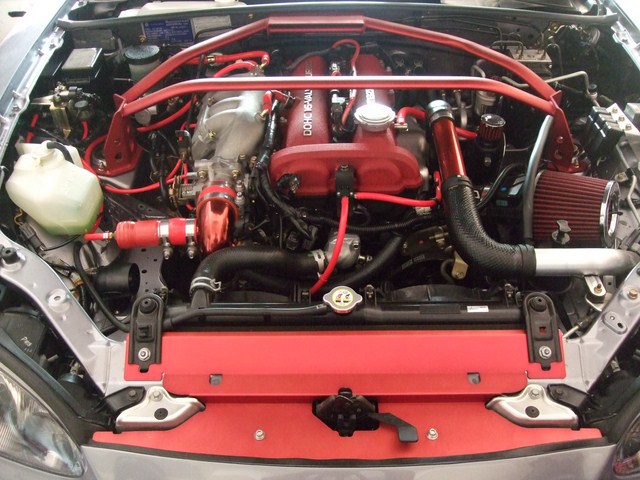
The OEM bonnet rod retainer looks much better now (ie. "less cheap" and more stealthy) but I'm sorely tempted to paint the Cooling Panel in VHT Red Fire engine metallic to match the TB Elbow and AEM intake pipe (and eventually the front strut brace) - probably not a good idea since it would be highly prone to scratching.


Originally posted by Crapweasel, Fri Dec 02, 2011 9:39 pm[

Nice work all round, I'm impressed!

Welcome to the 150+ club by the way!
Don't worry about dying, worry about not living!
Garage Thread: http://www.mx5cartalk.com/forum/viewtopic.php?f=57&t=76716

User avatar
Lokiel
Forum legend
Posts: 4126
Joined: Thu May 28, 2009 2:39 pm
Vehicle: NB SE
Location: Brisbania

Re: Lokiel's "Gina" (once a 2004 Titanium SE) Recreated AGAIN

Postby Lokiel » Tue Jun 05, 2018 7:51 pm

Originally posted by Lokiel, Sun Sep 24, 2017 3:56 pm

Originally posted by Lokiel, Sat Dec 03, 2011 10:55 pm[

I've always been concerned about how little fresh air actually gets to my radiator ever since installing my Cooling Pro intercooler. Not only does air have to pass through that, it must also pass through the A/C condensor before reaching the radiator.

I decided to purchase a BEGI Air Scoop (see http://www.bellengineering.net/product_info.php?cPath=4_26&products_id=71) because, according to the "propaganda":

"The 'Air Scooper'. It gathers air from beneath the car and channels 40% more air flow directly into the radiator. It helps to make the stock (or aftermarket) radiator cool more efficiently. The Scooper for the 1.8L bolts to the frame. All mounting hardware included."

40% more air flow, and fresh air at that, sounded like a good thing!

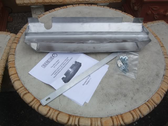
Here's the kit contents and how it's supposed to be mounted:

Image

Image


Here's my initial test fitting (note that the splash guard, valance and lower air deflector/director "plate" must be removed to install the air scoop):

Image


The test fitting revealed the following issues:

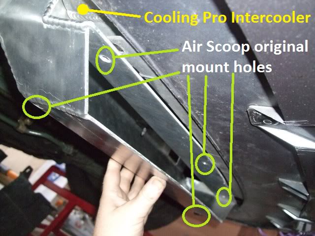
1. My Cooling Pro Intercooler must be deeper than what BEGI expected because the top 3 mount holes are at least 20mm behind the bumper's OEM bolt holes that they're supposed to mount to.

2. The three holes in the lower bumper, and matching holes in the valance and air deflector plate, were originally mounted to the OEM intercooler's lower bracket which had to be removed to fit the Cooling Pro so there was nothing solid to bolt the air scoop into anyway!

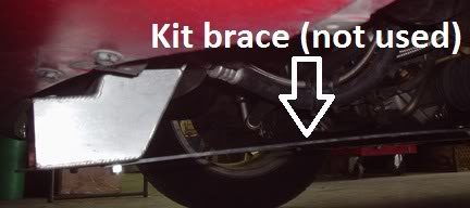
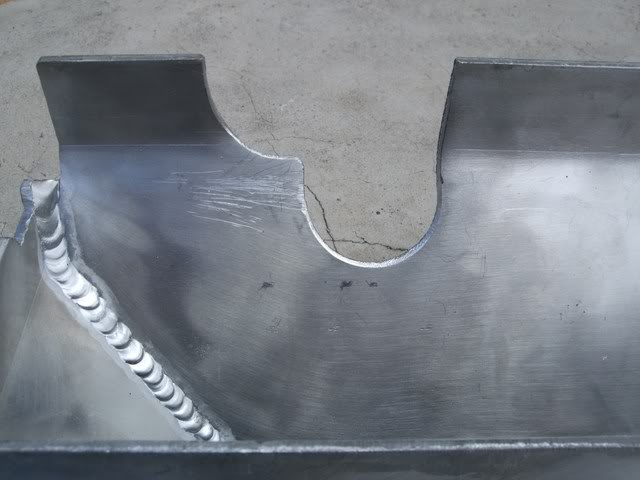
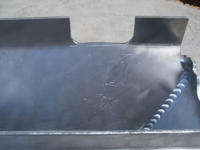
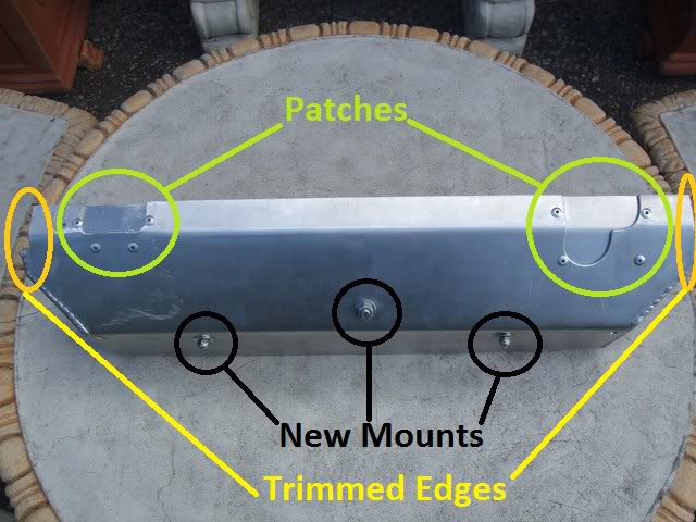
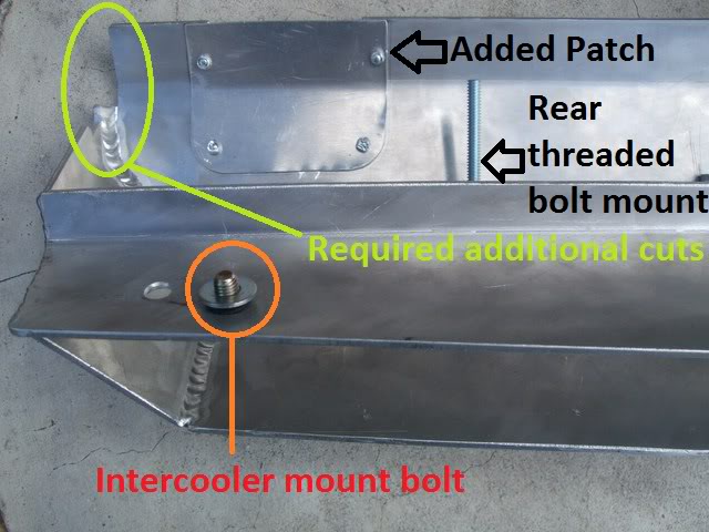
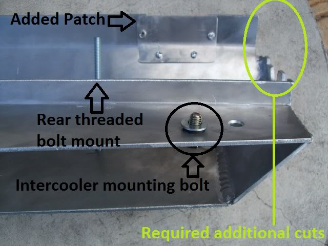
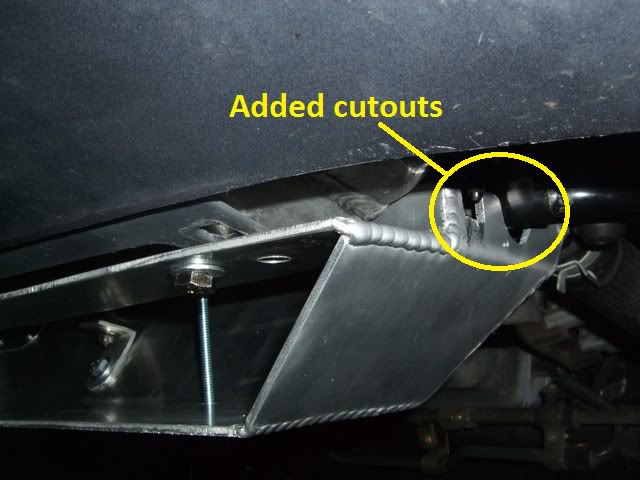
3. The two rear cut-outs on the air scoop aren't needed at all on an SE/MSM and the starboard one is so large that air would just rush straight through it. About 5mm needed to be cut off both rear edges to allow it to fit within existing bracing (you can see these cuts above the welds in these photos).
Image

Image

These holes would need to be patched!

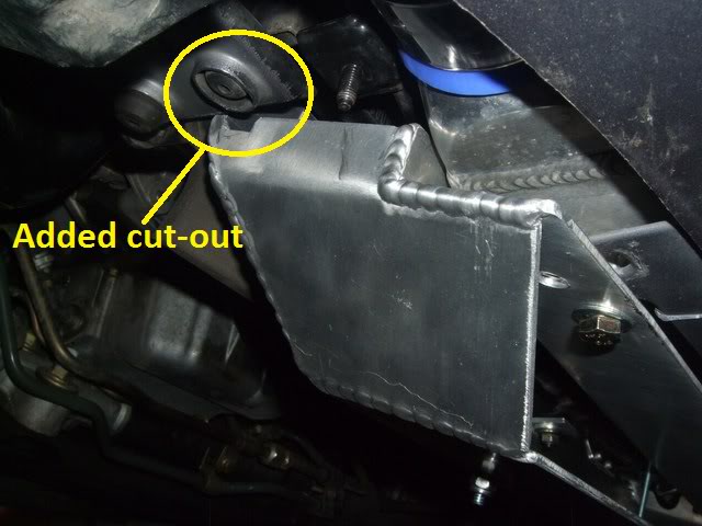
4. Since the air scoop needed to be mounted further back (about 20mm back), additional cuts on the left and right sides would be needed to fit over existing bolts, brackets and bars.

5. I really didn't want to use those long aluminium rods to mount the air scoop since I want to make some sort of undertray/splash guard.

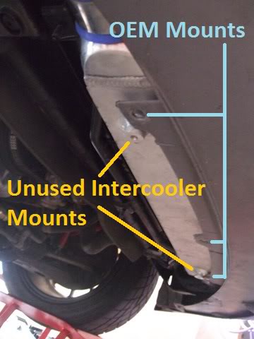
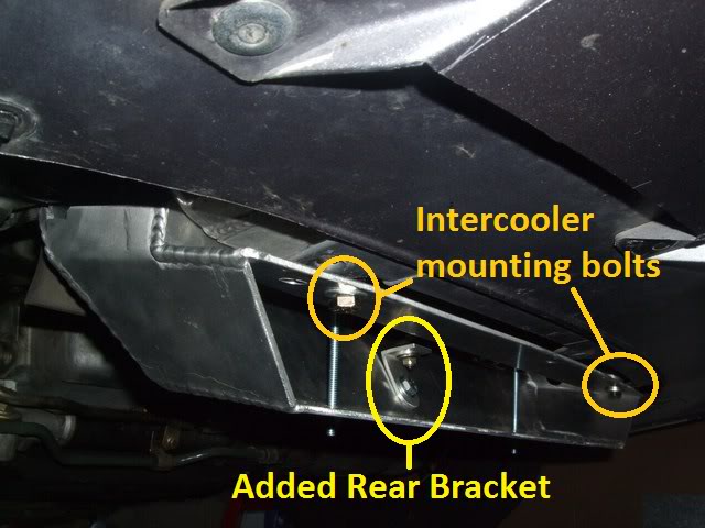
The intercooler has 2 unused bolt points so I decided to use those to mount the air scoop and drilled two new holes into the top front of the air scoop for these:
Image


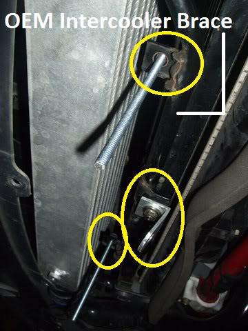
Under the car there is a round bar that runs in front of the radiator and has 5 mount points that the OEM intercooler bracket mounted to. I decided to use the three middle ones as rear mount points (the outer mount points contain pre-mounted bolts which can't be used since they're too close to the outside edges of the air scoop so you can't tighten a nut onto them):
Image

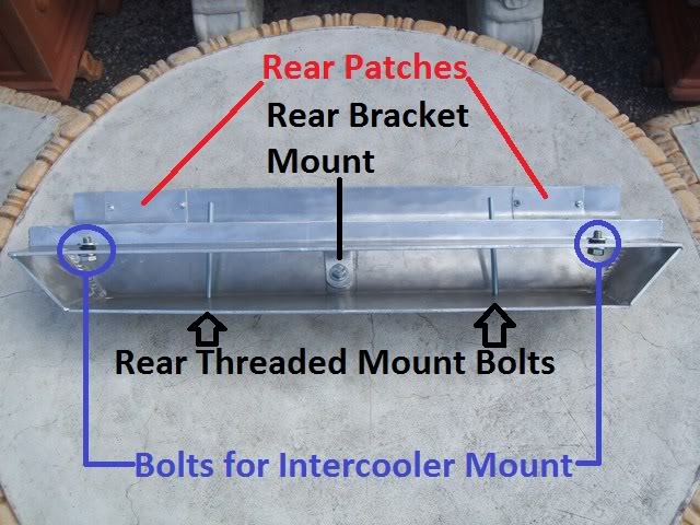
For the rear centre mount, I made an aluminium bracket (circled-centre) since it had a pre-mounted bolt.
I cut a threaded rod into two lengths and use these to attach to the bottom of the scoop (using nylock nuts for security) so that the intercooler wouldn't be bearing most of the weight. The two intercooler bolts and the rear centre bracket alone are actually strong enough to mount the air scoop securely, but not strong enough for my peace of mind.

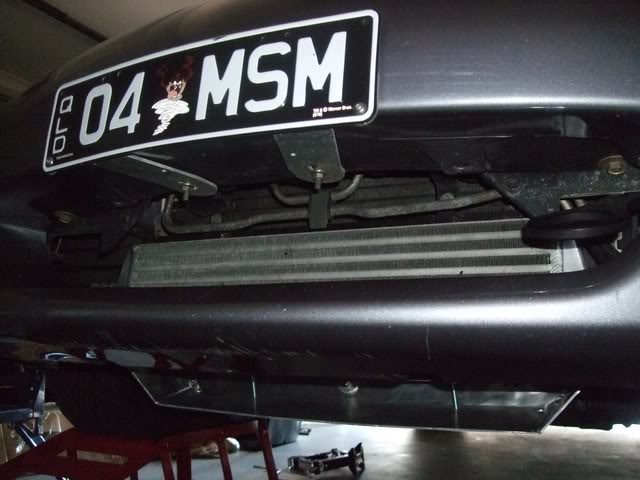
Here's a summary of all the air scoop modz required:
Image

Image

Image

Image


...and this is how it looks when mounted:
Image

Image

Image

Image


My air scoop mounting is a little higher, further back, and more angled than the BEGI mounting.

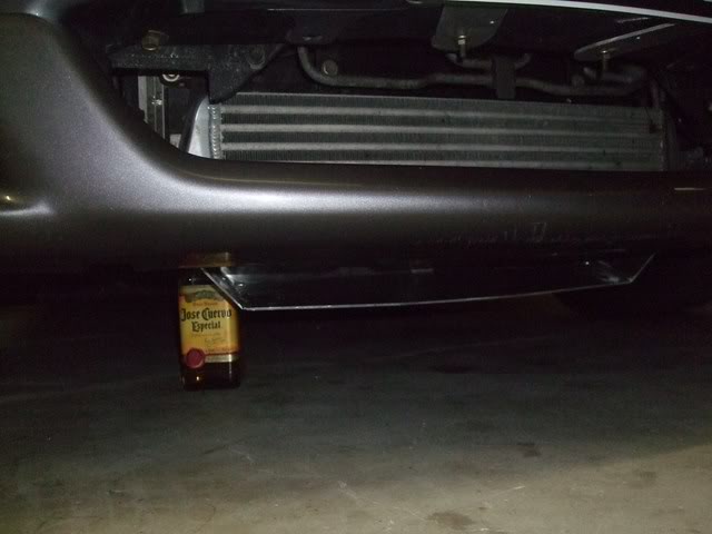
At the moment, the air scoop sit 110mm above the ground so I'm going to have to approach speed bumps and dips with extreme caution. I didn't have a can of Coke as a scale reference so used a bottle of Jose Cuervo Tequila instead (note: this photo was taken before the 2 tie rods were added):
Image


This install was a LOT of work. IMO, BEGI should simply sell the air scoop with NO cutouts or pre-drilled holes and I suspect that they would actually do so if you asked since it's less effort for them to produce that way.

I'm happy with this mod since there's no way it can't be effective, but now I have to do something about the undertray, not only does it help to keep water out of the engine bay, it also helps to channel air through the radiator.


Originally posted by Aussie Stig, Sun Dec 04, 2011 12:14 am[

Aiy Carumba! I hope you put the contents of that Tequila bottle to good use.
It's so low maybe you should call it a pooper scooper :lol: :lol:


Originally posted by Lokiel, Sun Dec 04, 2011 9:36 am[

Aussie Stig wrote:Aiy Carumba! I hope you put the contents of that Tequila bottle to good use.
It's so low maybe you should call it a pooper scooper :lol: :lol:


I've scraped the air scoop already backing out of a driveway on a hill so this may turn out to be a "Track Day Only" mod :(

- luckily it's easy to install/remove.
Don't worry about dying, worry about not living!
Garage Thread: http://www.mx5cartalk.com/forum/viewtopic.php?f=57&t=76716

User avatar
Lokiel
Forum legend
Posts: 4126
Joined: Thu May 28, 2009 2:39 pm
Vehicle: NB SE
Location: Brisbania

Re: Lokiel's "Gina" (once a 2004 Titanium SE) Recreated AGAIN

Postby Lokiel » Tue Jun 05, 2018 7:51 pm

Originally posted by Lokiel, Sun Sep 24, 2017 3:57 pm

Originally posted by Lokiel, Sun Dec 04, 2011 9:22 pm[

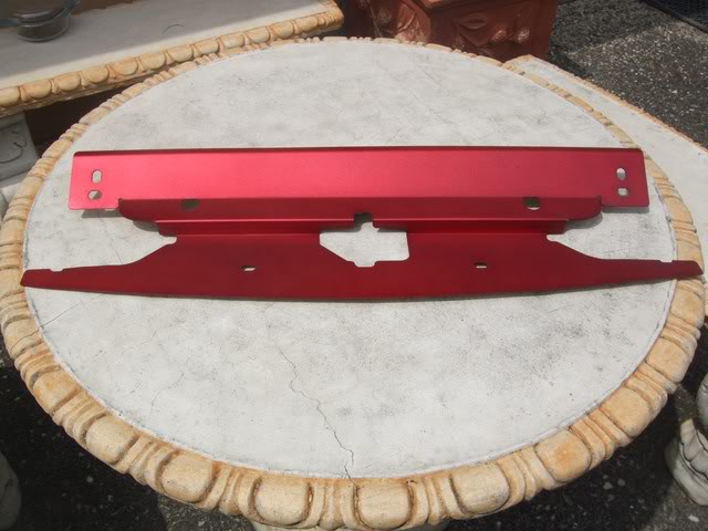
I wondered what the Beatrush radiator panel would look like in VHT's Red Anodised Colour Coat (same colour I painted the Flyin' Miata Throttle Body elbow and AEM CAI metal pipe) and Rupewrecht had a 2nd hand one for sale so I figured, why not try it? (I didn't want to risk it on the brand new panel, just in case I thought it would look like crap)

After a bit of a cleanup, here's what it looks like painted:
Image


...and here are comparison shots of the new Beatrush panel vs the painted 2nd-hand panel:
Image

Image

- I like it, definitely fits my red engine bay theme!

Close-up of the install:
Image


VHT's Red Anodised Colour Coat is designed to colour chrome so it wasn't surprising that painting the aluminium panel didn't look the same colour as the Flyin' Miata Throttle Body elbow and AEM CAI metal pipe. It is the colour I'd hoped that the front strut brace would turn out so I'll definitely be painting the strut brace to match it at some point.


Originally posted by Okibi, Mon Dec 05, 2011 12:12 am[

Looks like a freshly anodised part from those pics, might have to give it a go myself.
Don't worry about dying, worry about not living!
Garage Thread: http://www.mx5cartalk.com/forum/viewtopic.php?f=57&t=76716

User avatar
Lokiel
Forum legend
Posts: 4126
Joined: Thu May 28, 2009 2:39 pm
Vehicle: NB SE
Location: Brisbania

Re: Lokiel's "Gina" (once a 2004 Titanium SE) Recreated AGAIN

Postby Lokiel » Tue Jun 05, 2018 7:52 pm

Originally posted by Lokiel, Sun Sep 24, 2017 3:57 pm

Originally posted by Lokiel, Fri Dec 30, 2011 7:13 pm[

This Xmas break I finally got the time and good weather to re-paint my Carbing 3-point front strut brace in VHT's Red Anodised Colour Coat to match my Beatrush radiator panel and am just posting now:

Before (not "red enough", too orange for my liking):
Image


After ("red enough" now):
Image
Image


Now when I open the bonnet, the red Beatrush radiator panel really hits you "BAM" in the face - the re-painted front strut brace fits the red theme better too!

I think I'm done now "Exhausting the reds" (Eddie and the Cruisers II - bad acting/script, great music).


I also removed the front air scoop after posting it at http://www.mazda-speed.com/forum2/index.php/topic,24999.0.html and gaining some useful information. The key point made was that by ducting air under the intercooler and onto the radiator, what was previously a low pressure area (ie. directly behind the intercooler), was now a positive pressure area, which means that less air would flow through the intercooler, making the intercooler less effective. In a turbocharged car, cooling charged air is more more important so I removed the scoop.

Ideally, the intercooler should be a large as the radiator and A/C's condenser and the air should be channelled to pass through the intercooler+condenser+radiator "sandwich" in turn so that there are no low or high pressure areas that affect air flow. The OEM SE/MSM now looks like it was more of a token effort on Mazda's part given how small it was and I now think I really need a taller intercooler since a lot of air must simply flow over the top of it. A Mishimoto M-Line intercooler would seem to be an ideal fit: http://www.jscspeed.com/catalog/Universal_Parts/Universal_Cooling_Components/Mishimoto_Universal_Intercoolers.html

Given how low the front air scoop was, it was surprising that it didn't scrape as much as I feared it would. Reversing out of driveways was the biggest problem, it scraped EVERY time. Occasionally it would scrape when driving forwards out of a driveway but speedbumps weren't a problem - apart from the "Evil One" at the QLD Cannon Hill car park (between Kmart and the Kmart garage).
Don't worry about dying, worry about not living!
Garage Thread: http://www.mx5cartalk.com/forum/viewtopic.php?f=57&t=76716

User avatar
Lokiel
Forum legend
Posts: 4126
Joined: Thu May 28, 2009 2:39 pm
Vehicle: NB SE
Location: Brisbania

Re: Lokiel's "Gina" (once a 2004 Titanium SE) Recreated AGAIN

Postby Lokiel » Tue Jun 05, 2018 7:52 pm

Originally posted by Lokiel, Sun Sep 24, 2017 3:58 pm

Originally posted by Lokiel, Wed Feb 22, 2012 10:52 pm[

I've wanted to install an oil cooler in my car for a while now so about a month ago started on the task.

First up I removed my foglights since I planned to mount the oil cooler behind the starboard foglight. There's not too many other mounting options in the SE since I have a large aftermarket intercooler, OEM A/C condenser and radiator all occupying the front of the engine bay so there's not a lot of room there, unlike behind the foglight - look at all that room:
Image

- I'll explain that yellow-circled thumb-fastener below.

I purchased a "spare" Works Engineering kit from Apu since he gave it rave reviews with regard to quality and said the banjo fittings made it easy to install - fitting oil hoses is one of the most common complaints so this was a bonus:
Image
Image
Apu was correct with regard to the quality of the kit; I was worried since the kit is badged as "Designed in the USA" which typically means it's actually manufactured in China but it's quite good and the block adapter comes with two O-rings (some of the well-known kits only have one O-ring).
The length of the hoses was about 4 times longer than I actually required, I could probably have mounted the oil cooler at the rear of the car!

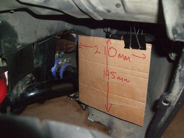
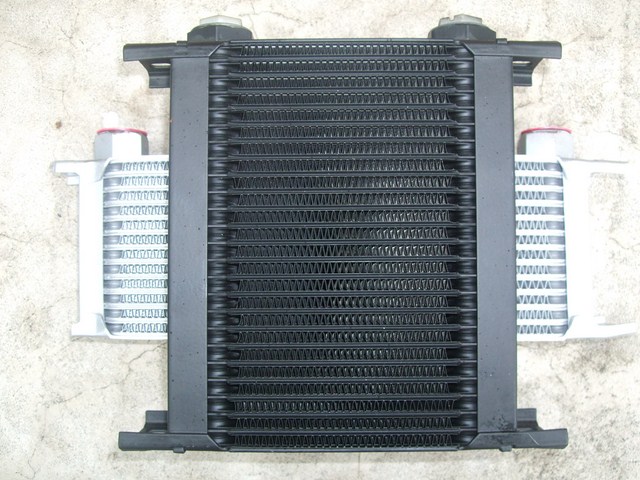
Unfortunately for me, the oil cooler was too wide to fit behind the foglight (that intercooler pipe is in the way), I needed something squarer rather than something wide and short. After a bit of hunting on the "internets", I found the Setrab STD Narrow 25-row Oil Cooler (L:210mm, H:193mm, D:50mm; 2xM22 connections). A quick template mock-up confirmed that this oil cooler was ideal:
Image


I needed the car operational while waiting for the new oil cooler and I didn't want to re-install the foglights only to remove them again so installed foglight blanks instead:
Image

Image

- I think they look better than the OEM foglights and bought these ages ago since foglights are useless in Brisbane anyway.

Here's the new Setrab oil cooler (top) vs the Works Engineering oil cooler (bottom):
Image

I also purchased the Setrab mounting kit, 2xM22->AN-10 barbs and 2xM22->AN-10 90 degree fittings to give me as many mounting/install options as possible.

Figuring out how to mount the cooler in the wheel well took a while, I didn't want to drill any new holes if possible and wanted to preserve as much of the undertray and wheel well liners as possible.

Initially I made a steel L-shaped bracket that attached vertically to the chassis (with 2x45 degree bends required to locate the cooler as far right as possible) and to the underside of the Setrab cooler so that the barbs were on top of the cooler. After reading this site http://www.racing-stuff.com/coolers.htm, I decided to rotate the oil cooler anti-clockwise 90 degrees since that's supposedly more efficient and will make it easier to drain the oil from the oil cooler when doing oil changes.
Lucky for me, the oil cooler is almost square, the barbs clear the intercooler pipe and will make routing the oil hoses a bit easier.

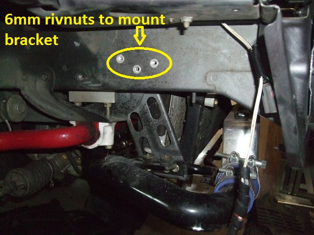
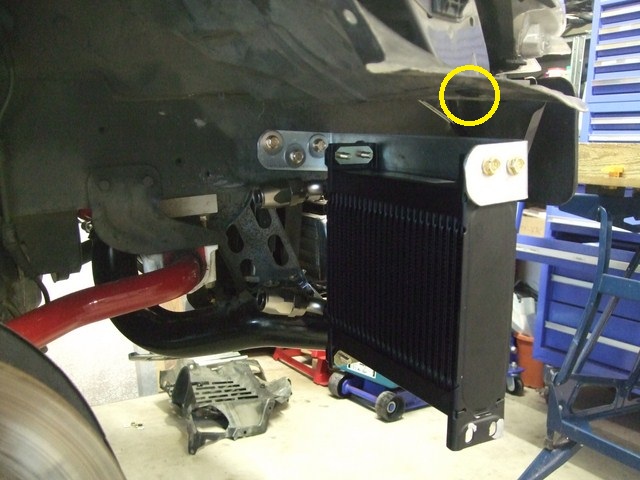
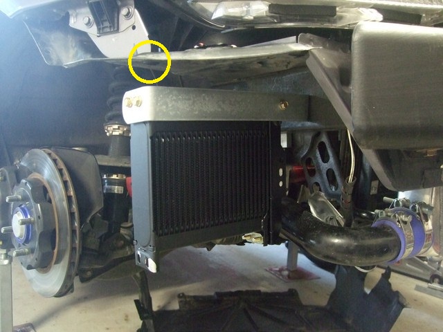
I made a new steel bracket and drilled 3x6mm rivnuts into the chassis to support the top of the cooler:
Image

Image

Image

- so what are those yellow circles about? Keep reading...

The bracket supports the oil cooler well enough but it does "bounce".
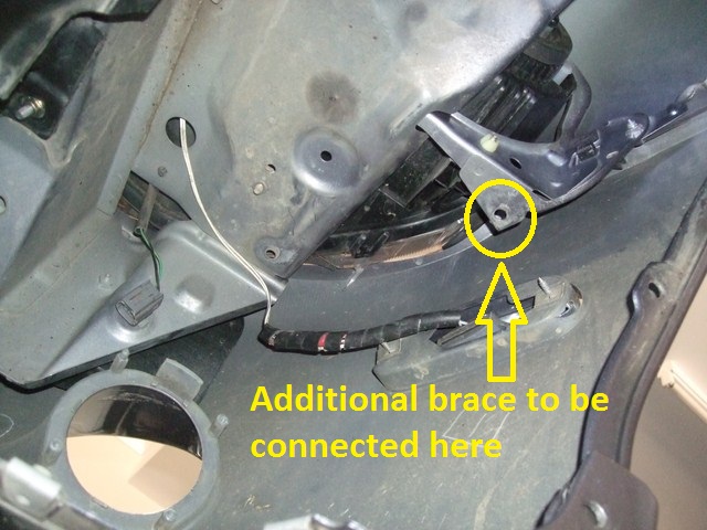
The "baby teeth" in my car have been long removed so I can use one of the starboard "baby tooth" bolt points to brace the lower port side of the oil cooler using another brace (this weekend's job).
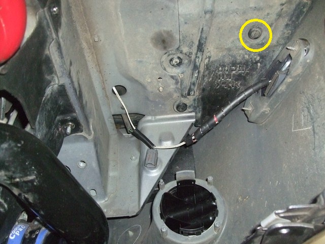
To brace the top starboard corner of the oil cooler, I'm going to add a bracket that mounts to the OEM wheel liner "thumb-fastener" circled in yellow below:
Image

- this is the same thumb-fastener referred to initially (and the other photos); this picture shows it with the wheel well liner removed. I'm going to use a bolt through this hole - it's not intended to bear weight but merely brace the starboard side of the oil cooler to minimise "bounce".

I plan on adding an aluminim shroud to funnel all air from the foglight opening through the oil cooler too (another job for this weekend).

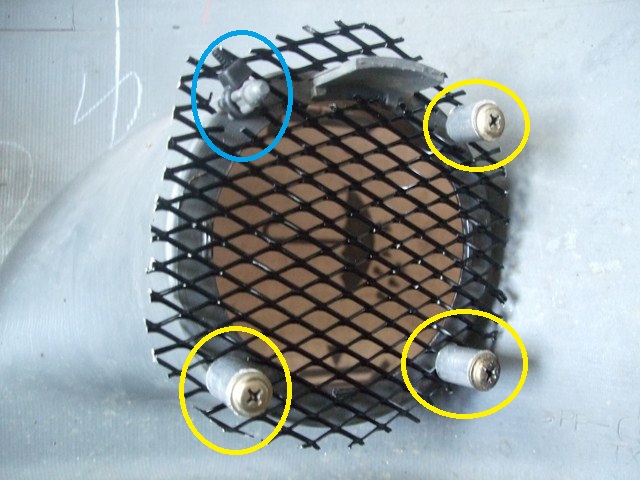
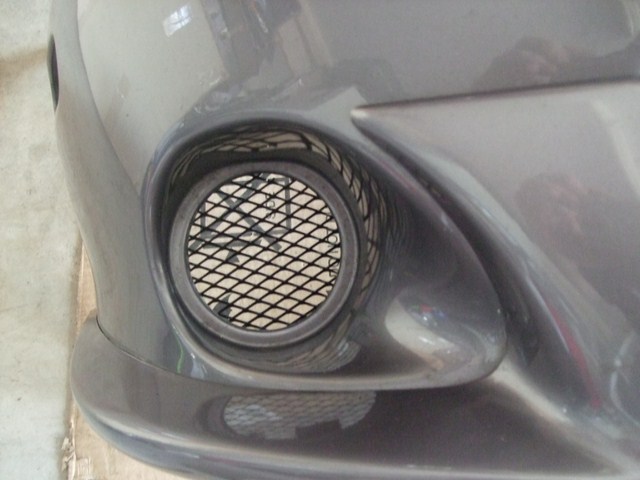
The "empty" foglights were covered using SuperCheap mesh. I used some 16mm aluminium round tubing and the 3xOEM screws (yellow) to secure the mesh to the bumper and a cable-tie for the 4th locator pin (blue):
Image

Image
Don't worry about dying, worry about not living!
Garage Thread: http://www.mx5cartalk.com/forum/viewtopic.php?f=57&t=76716

User avatar
Lokiel
Forum legend
Posts: 4126
Joined: Thu May 28, 2009 2:39 pm
Vehicle: NB SE
Location: Brisbania

Re: Lokiel's "Gina" (once a 2004 Titanium SE) Recreated AGAIN

Postby Lokiel » Tue Jun 05, 2018 7:53 pm

Originally posted by Lokiel, Sun Sep 24, 2017 3:59 pm

Originally posted by timk, Wed Feb 22, 2012 11:21 pm[

Good location for the cooler!

You realise you'll have to come to some track days to justify all this work! :lol:


Originally posted by Apu, Thu Feb 23, 2012 6:23 am[

That's a lot if detailed effort Lokiel! Just curious if the Works Engineering cooler wouldn't have fitted sideways?

All in looks like an excellent install!


Originally posted by Lokiel, Thu Feb 23, 2012 11:19 am[

saboteur wrote::You realise you'll have to come to some track days to justify all this work! :lol:


That's the plan this year and I'm hoping to get to the track in March. I still need to finish up this oil cooler mount, shroud, figure out how/where to mount the oil filter relocation block and am still waiting on my PLX sensors (oil temp, oil pressure, water temp, wideband O2 sensor) and gauge that I've ordered.

I planned to use the PLX DM-100 multi-gauge which can display 4 sensor values at a time, see http://www.plxdevices.com/gauges.php, so that I don't need "a bazillion" gauges in the cabin but that's out of stock for several weeks so I purchased the DM-6 Multi Gauge and Wideband Air Fuel Ratio Sensor Module Combo, http://www.plxdevices.com/wideband.php, for now. The DM-6 Multi Gauge only displays one sensor at a time but you can manually cycle through each connected sensor. I'm going to install the gauge in the existing A-Pillar AFR gauge position which is why I need to replace the Innovate LC-1 sensor with the PLX one.


Apu wrote:That's a lot if detailed effort Lokiel! Just curious if the Works Engineering cooler wouldn't have fitted sideways?
:


I trimmed the bottom mounts of the Works Engineering oil cooler but it still would't fit when mounted with the barbs on top unless it was tilted, it's just too wide and the intercooler pipe is in the way. Unfortunately when spun 90 degrees, it's too tall and I would have needed to trim all the mounts to get it to fit, leaving me with no way to mount it.

With the Setrab unit's face being almost square instead of a thin rectangle, air should flow more evenly and better through the yet-to-be shrouded cooler. The Works Engineering oil cooler has a thin rectanglular face so air redirected from the foglight entrance wouldn't flow as well through the extremities, reducing its cooling capacity.


Originally posted by Apu, Thu Feb 23, 2012 11:38 am[

That makes sense. I did consider mounting it behind the radiator, or in front of it...but am still considering a turbo so that would mean relocating it because of the intercooler.

Just some pondering as I was praying to the porcelain god...with the behind-the-foglight location - the foglight opening would be good at channeling air...but at speed, wouldn't it be funnelling air into a smaller area on the cooler? You'd want air to hit as much surface area on the cooler.

As for relocater kit location - would mounting on the strut bar work for you?

The other option is to mount it in the firewall cavity where the Nopro washer bottle would fit. No problem with oil spills!


Originally posted by timk, Thu Feb 23, 2012 11:46 am[

From my very limited knowledge of fluid dynamics, if you can smoothly duct from the foglight size to the full size of the cooler, the air will have a tendency to stick to the walls of the duct.

This should also lower the pressure, encouraging more air to enter the foglight hole.


Originally posted by Lokiel, Thu Feb 23, 2012 1:32 pm[

Apu wrote::
Just some pondering as I was praying to the porcelain god...with the behind-the-foglight location - the foglight opening would be good at channeling air...but at speed, wouldn't it be funnelling air into a smaller area on the cooler? You'd want air to hit as much surface area on the cooler.

As for relocater kit location - would mounting on the strut bar work for you?

The other option is to mount it in the firewall cavity where the Nopro washer bottle would fit. No problem with oil spills!


Regarding air flow and surface area: As far as I know (which is very little), air likes to take the path of least resistance so you want to present the largest surface area possible and ensure that all air passes through this surface (via ducting). At speed, the duct will become a high pressure area so air will be forced through every available vent in the oil cooler.

I'm open to all options with regard to mounting the oil filter relocator EXCEPT "the firewall cavity where the Nopro washer bottle would fit" because there is a NoPro washer bottle in the way :P


Originally posted by Apu, Thu Feb 23, 2012 2:07 pm[

Haha! Not much choices with an SE huh? Talk about tight!

I'm very keen to see how you will do the ducting!
Don't worry about dying, worry about not living!
Garage Thread: http://www.mx5cartalk.com/forum/viewtopic.php?f=57&t=76716

User avatar
Lokiel
Forum legend
Posts: 4126
Joined: Thu May 28, 2009 2:39 pm
Vehicle: NB SE
Location: Brisbania

Re: Lokiel's "Gina" (once a 2004 Titanium SE) Recreated AGAIN

Postby Lokiel » Tue Jun 05, 2018 7:53 pm

Originally posted by Lokiel, Sun Sep 24, 2017 3:59 pm

Originally posted by Lokiel, Sat Feb 25, 2012 8:44 pm[

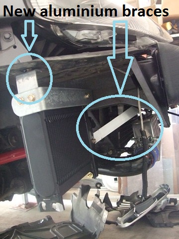
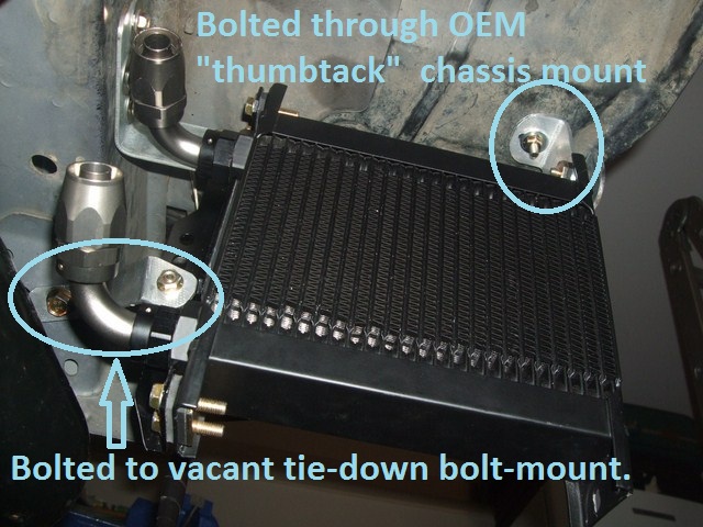
I finished off bracing the oil cooler today by making two aluminium brackets, the top starboard mount is bolted through an OEM "thumbtack" chassis mount which also holds the wheel splashguard in place, and the lower port side is mounted to a previously-vacant tie-down hook bolt point:
Image

Image


The aluminium braces are not weight-bearing brackets and were added to stop the cooler from "bouncing" - they work great, there's very little movement now unless you really yank the un-braced lower starboard corner.

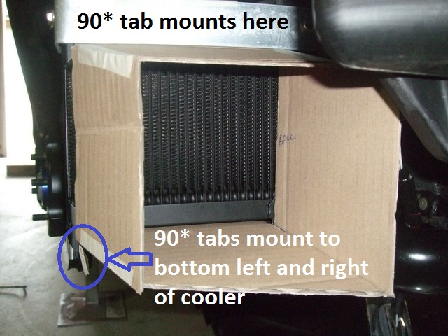
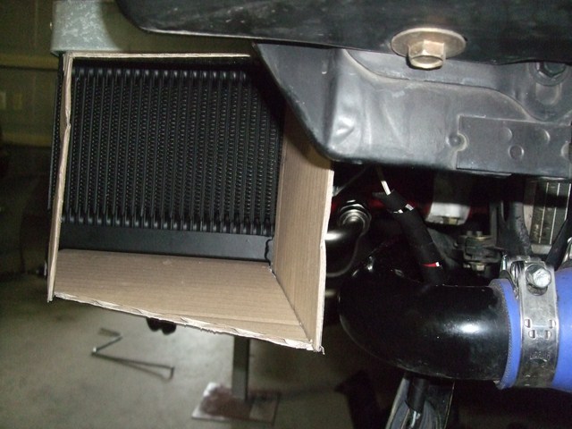
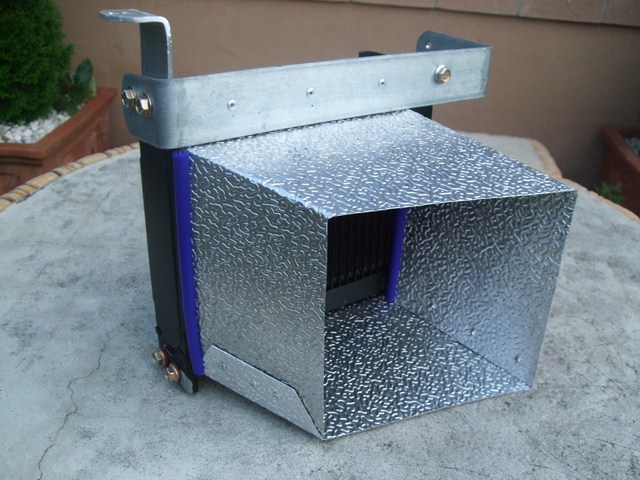
Even with the square-shaped oil cooler in place, there's a LOT of space around the cooler in the wheel well so a shroud is required to ensure that as much air entering the foglight as possible flows through the oil cooler rather than around it. I spent about 2 hours making cardboard mockups of the shroud to ensure that I got it right since I don't want to waste a sheet of aluminium screwing up. Here's what I came up with:
Image

Image


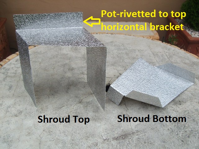
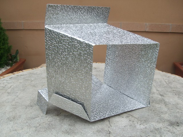
The top of the shroud has a 90* tab that will be pot-rivetted to the top steel brace.
The bottom of the shroud extends to the back of the oil cooler and has 2x90* tabs that will be bolted to the oil cooler's 2 bottom port and starboard mounting tabs.

There's about 10mm of clearance between the bumper and the front starboard side of the shroud which is angled so that the foglight is comfortably within its centre so I'm confident that all possible air will be directed through the oil cooler since it will become a high pressure area when in motion.

Luckily for me, this mockup can be cut from a single aluminium sheet and will only require pot-rivetting one of the sides to form the box - that's tomorrow's job (I didn't want to rush it trying to finish it today).


Does anyone know if it's safe for me to put a rubber/silicon hose edging on the rear vertical edges of the shroud to seal it against the oil cooler or will they melt?


Originally posted by Lokiel, Sun Feb 26, 2012 10:08 pm[

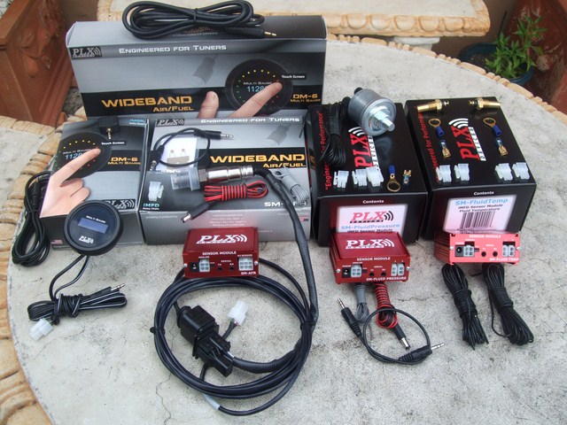
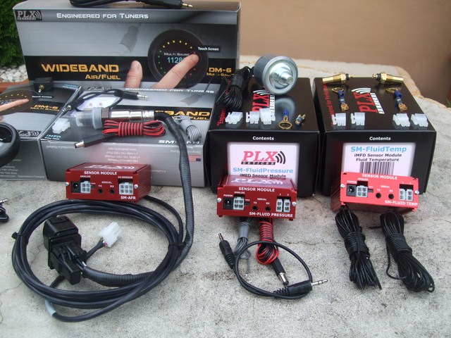
I got a bit distracted today with the delivery of my PLX sensors (Wideband O2, Oil Pressure, Oil Temperature and Water Temperature) and Gauge (DM-6):
Image

Image

- going to be a lot of work to install :(

I wanted to install oil pressure and temperature sensors in conjunction with my oil cooler but didn't want to clutter up the car, or find space for, the associated gauges. PLX have a DM-100 sensor that can display up to 4 sensors simultaneously in digital format so that seemed like a good choice. I planned to replace my existing A-pillar mounted AFR sensor with the DM-100 so I decided to switch to the PLX sensor too which, unlike the Innovate LC-1 sensor, doesn't need periodic fresh air calibration which is a good thing (removing the sensor bung from the exhaust is a B-I-A-T-C-H-!-!-!). That left one more sensor to be displayed so a real water temperature sensor was the obvious choice.
Unfortunately for me, the DM-100 is out of stock for several months so I opted for the Wideband+DM-6 gauge package. Multiple sensors can be daisy-chained to the DM-6 gauge and it can cycle through them, one at a time, with each press of the gauge. The package isn't bad value since it means the gauge only costs an additional US$50. I may even keep it when I get the DM-100 - if I can fit it somewhere.

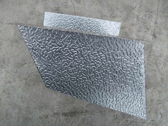
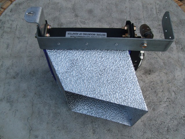
After that distraction, I continued to fabricate the oil cooler shroud. Originally I was going to cut it as one piece but realised that the tab needed to pot-rivet the box wouldn't fit so I made it in 2 pieces, a top and bottom:
Image

Image


This top-down view shows how much shround angle was required to centre the foglight in the mouth of the shroud:
Image


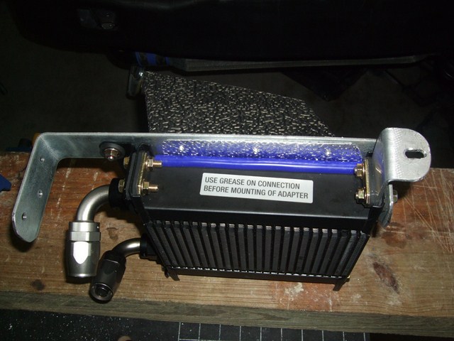
I decided to add split silicon hose to the rear vertical edges of the shroud, they help seal the shroud against the cooler and provide padding between them:
Image

Image

- Yeah, I screwed up, the top starboard bracket is mounted the wrong way - lucky the Loctite wasn't added yet.

There was a small gap between the top horizontal bracket and the cooler so I added split silicon hose to fill it:
Image

- Yeah, the top starboard bracket is still mounted the wrong way.

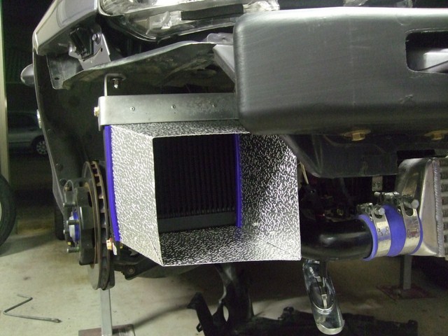
Here's the oil-cooler assembly mounted on the car:
Image

Image

Image

- note that the top starboard bracket is NOW mounted the right way!

Next weekend comes the hard part, figuring out how to route the stainless steel hoses and where/how to mount the oil filter relocation block.


Originally posted by charlie_91, Sun Feb 26, 2012 10:24 pm[

awesome work. very clean install


Originally posted by NitroDann, Mon Feb 27, 2012 12:30 am[

Apu wrote: the foglight opening would be good at channeling air...but at speed, wouldn't it be funnelling air into a smaller area on the cooler? You'd want air to hit as much surface area on the cooler.


Some common misconceptions about cooling there.

Lets looks at the size of a stock radiator, not how big is the opening? its about 1/3rd of the size of the rad.

Look at a radiator head on, how much of what you see is radiator, and how much is actual gaps air can flow through, the gaps, are 1/3.

Follow me?

Dann
Don't worry about dying, worry about not living!
Garage Thread: http://www.mx5cartalk.com/forum/viewtopic.php?f=57&t=76716

User avatar
Lokiel
Forum legend
Posts: 4126
Joined: Thu May 28, 2009 2:39 pm
Vehicle: NB SE
Location: Brisbania

Re: Lokiel's "Gina" (once a 2004 Titanium SE) Recreated AGAIN

Postby Lokiel » Tue Jun 05, 2018 7:53 pm

Originally posted by Lokiel, Sun Sep 24, 2017 4:00 pm

Originally posted by Lokiel, Sat Mar 03, 2012 11:41 pm[

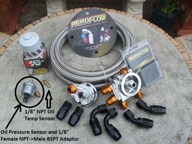
I finally got all of the components required to install the GREDDY Oil Filter Relocation Block Thermostat:

Image

Starting from the top and going clockwise:
* 4.5m AeroFlow 10-AN Stainless Steel hose (probably could have gotten away with 2.5m)
* Trust/Greddy Oil Filter Relocation block with built-in thermostat
* 2xAeroFlow 10-AN 45* barbs (these connect to the Trust/Greddy engine block)
* 2xAeroFlow 10-AN 90* barbs (these connect to the Oil Cooler)
* 2xAeroFlow 10-AN straight barbs (these connect to the Trust/Greddy oil relocation block)
* Trust/Greddy Oil Filter Relocation block
* PLX 1/8" NPT Oil Temperature sensor
* 1/8" NPT Female -> 1/8" BSPT Male brass adaptor (http://www.speco.com.au part#543-31)
* PLX 1/8" NPT Oil Pressure sensor
* K&N HP-1009 Oil Filter

The "problem" with the Trust/Greddy blocks is that they use 1/8" BSPT-28 (British Standard Pipe Thread) sensor fittings whereas my PLX sensor fittings are 1/8" NPT-27 (National Pipe Thread) - this probably explains why not many people have used the Trust/Greddy blocks in the US since NPT fittings are the standard.
NPT threads are tapered and are the standard in the US. BSPT fittings, referred to as "PT fittings" in Japan, are used in England and Japan - Trust/Greddy is a Japanese company. Because of the different thread sizes (28 vs 27) you cannot simply tap from one to the other and you need to use an adaptor (Note: 1/8" BSP-28 male barbs can be screwed into 1/8" NPT-27 female sockets but it is a very loose fitting and definitely NOT airtight - don't do it!).

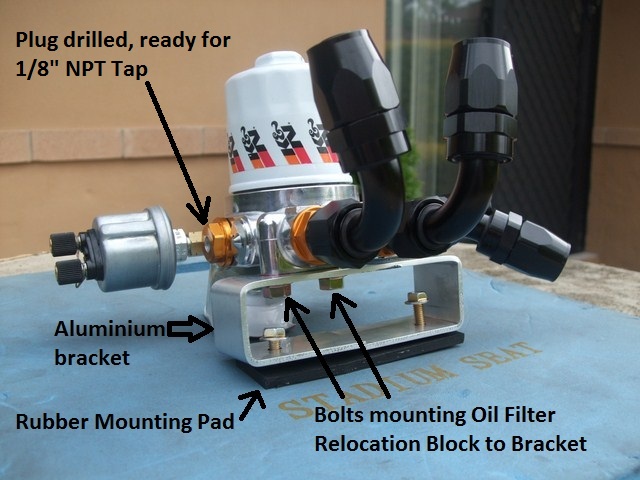
I'm using the 1/8" NPT Female -> 1/8" BSPT Male brass adaptor to mount the PLX Oil Pressure sensor and have drilled-out the Trust/Greddy M18 plug to tap it with a 1/8" NPT-27 tap for the PLX Oil Temperature sensor.

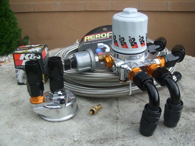
Here's how all the components are fitted, except the Oil Temperature sensor:
Image

The two 90* barbs connect to the Oil Cooler.
The two 45* barbs on the right connect to the two straight barbs on the Trust/Greddy engine block and are spun 180* when installed in the engine bay.

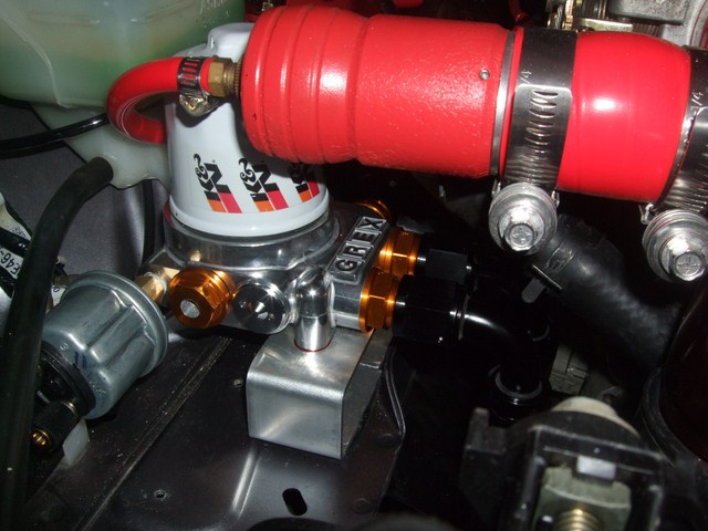
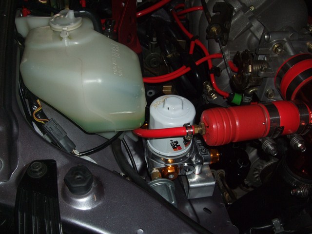
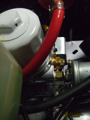
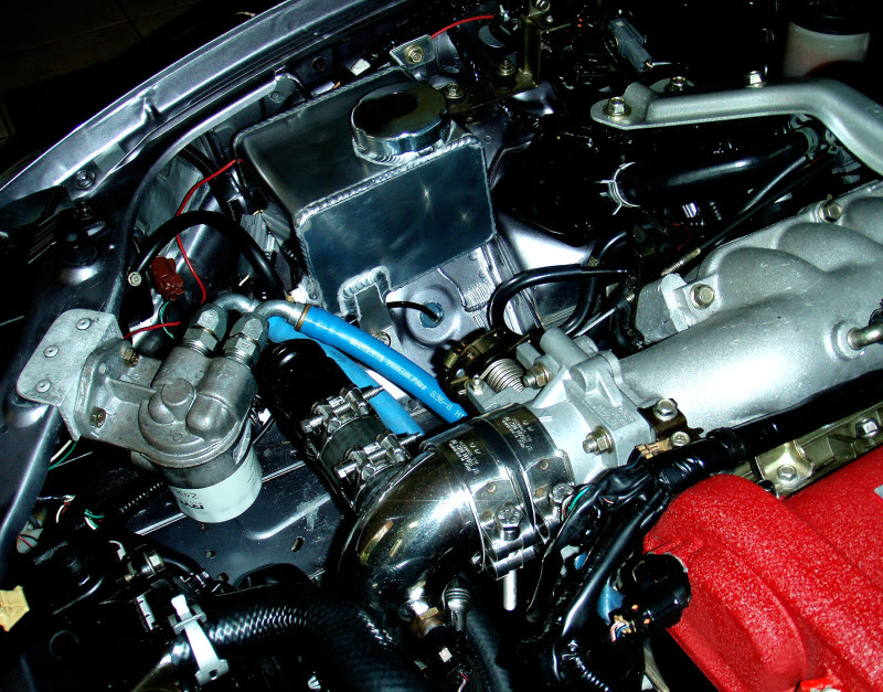
I don't have much space in my engine bay and the only place to mount the Oil Filter Relocation block is next to the radiator overflow bottle and behind the BOV. Luckily for me, there was already a threaded M6 mount point in that vicinity and another OEM hole I could use with a M6 rivnut (sailaholic introduced me to rivnuts and I can't believe I've lived without them for so long). I needed to elevate the block though because there is a 45* OEM bracket in the way (used to mount the Charcoal Cannister) that prevents one of the oil hoses connecting to the engine block mount without kinking. To make the bracket look tidy I decided to make the bracket as a "box" - the oil relocation block needed to be mounted high enough that it allowed me to screw the bolts from "the inside" of the box:
Image


Here's the block mounted in the engine bay, fittings secured with Permatex High Temperature Thread Sealant and bolts secured with Blue Loctite:

Image

The yellow circle indicates the two 45* barbs that connect to the block on the engine - you can see the OEM 45* brace just below the two red hoses. The barb on the left clears this brace by about 5mm.
The green circle indicates the two 90* barbs that connect to the Oil Cooler.

Image

This photo shows that the bottom of the bracket is not perfect - it sits flat on top of the rubber mount but it's "off" by a couple of mm ( my 90* angled bracket bends weren't perfect :( )

Image


The AN vice jaws I ordered haven't arrived yet :(

Image

These vice jaws make it easier to fit the stainless steel hoses to the AN fittings without damaging the fittings too much so I'll wait until they arrive before I install the hoses - next weekend's job.


Originally posted by MINX, Sun Mar 04, 2012 5:25 am[

Good work Simon.

Would be awesome if you could run the guages without the cooler for a while to set benchmark temps, then plumb in the cooler to see the difference.

Stu
Don't worry about dying, worry about not living!
Garage Thread: http://www.mx5cartalk.com/forum/viewtopic.php?f=57&t=76716

User avatar
Lokiel
Forum legend
Posts: 4126
Joined: Thu May 28, 2009 2:39 pm
Vehicle: NB SE
Location: Brisbania

Re: Lokiel's "Gina" (once a 2004 Titanium SE) Recreated AGAIN

Postby Lokiel » Tue Jun 05, 2018 7:54 pm

Originally posted by Lokiel, Sun Sep 24, 2017 4:01 pm

Originally posted by Steampunk, Sun Mar 04, 2012 9:19 am[

Lookin good Lokiel, nice'n'neat.
Have you given accommodation for easy removal of the bottom of the shroud to remove built-up debris? If it's all gonna be pop riveted, then a trap-door?


Originally posted by Lokiel, Sun Mar 04, 2012 10:31 pm[

^
Unfortunately I didn't think that far ahead Andrew - hopefully I can clean it out through the fog light grill using a vacuum cleaner and a custom coat hanger.

I didn't get as much done today as I'd hoped :(

sailaholic dropped off his tap&die set last night which included a 1/8"-NPT27 tap so I finished tapping the M18 plug today and installed the oil sensors, connecting them to a 6-pin blade plug (the oil temperature sensor has 2 connectors; the pressure sensor has 3 - one is an alarm indicator when the pressure drops below 11psi that I can hook up to a buzzer or LED).

Image


I needed to use a washer on the oil pressure sensor barb (see right side of brass connector above) to ensure that the sensor's ring connector was securely mounted and not spinning freely - that turned out to be a lucky break because the gap between the oil pressure sensor housing and the oil temperature sensor's connector is only about 1-2mm.The sensors are mounted securely to the Trust/Greddy block so there is no change of them contacting each other when driving.

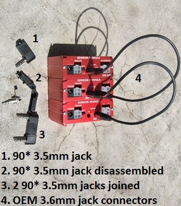
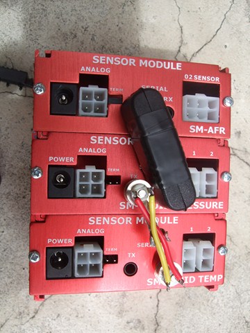
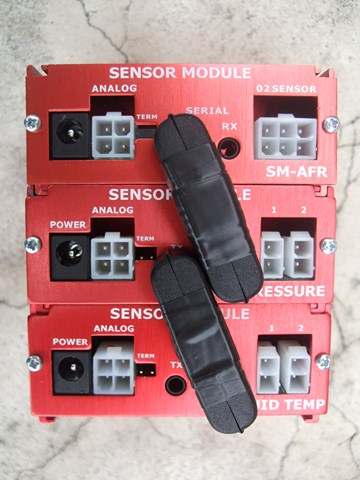
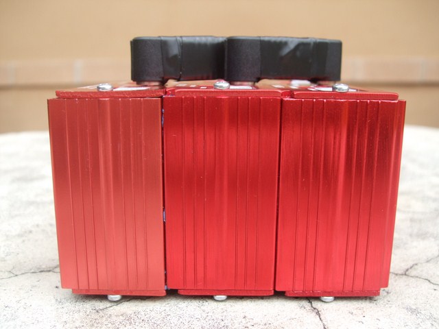
The PLX sensor module cases are made of extruded aluminium and are designed to interlock. Unfortunately 2 of them required me to sandwich the cases between two blocks and belt them together with a rubber mallet about a dozen times - car modding, Jeremy Clarkson style. Obviously I'd disassembled the sensors before doing this. These two cases aren't going to be separated again - EVER. The other case slid on with ease so I decided to use some gasket sealant in the tracks to hold it firmly in place. Initially it didn't look like it would work because it seemed that all the gasket sealant simply squeezed out as I joined the cases and the cases easily slid apart. After several hours, the cases were locked securely so there must have been just enough gasket sealant still in place to lock the cases together.

The PLX sensor modules and multi-gauges are designed so that they can be daisy-chained together and any sensor can be displayed on any of their multi-gauges. To do this, PLX supplied 250mm 3.5mm jacks that connect from one Tx socket to the next Rx socket in the daisy chain. This looks pretty messy so I decided to use some 90* 3.5mm jack connectors from Jaycar instead:

Image

Image

Image


You can see from the profile shot that it's much tidier (you can also see some of the gasket sealer):
Image


Unfortunately each sensor module requires its own power connector too :(
Ideally I'd like to make a power-rail that connects all modules by simply plugging in the rail but I can't find any 90* power connectors similar to the 3.5mm jack connectors.

When I figure out where to mount these sensors (probably in the passenger cabin or glovebox) I may get a better idea of how to power the module.


Originally posted by timk, Sun Mar 04, 2012 11:01 pm[

I'm loving the attention to detail. Thanks for being so verbose with your install!
Don't worry about dying, worry about not living!
Garage Thread: http://www.mx5cartalk.com/forum/viewtopic.php?f=57&t=76716

User avatar
Lokiel
Forum legend
Posts: 4126
Joined: Thu May 28, 2009 2:39 pm
Vehicle: NB SE
Location: Brisbania

Re: Lokiel's "Gina" (once a 2004 Titanium SE) Recreated AGAIN

Postby Lokiel » Tue Jun 05, 2018 7:54 pm

Originally posted by Lokiel, Sun Sep 24, 2017 4:02 pm

Originally posted by Lokiel, Sat Mar 10, 2012 9:58 pm[

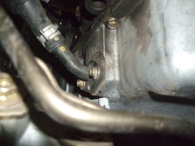
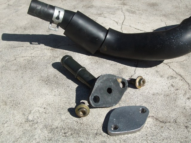
I got a late start today so started by draining the oil, removing the manifold->engine block brace (you need to do this on an SE/MSM to access the oil filter) and removing the OEM oil catch can oil return line shown below:

Image


On SEs/MSMs, the OEM oil catch can is mounted on the front strut brace on the starboard side; oil is returned to the oil pan via the oil return line shown above and the can is vented back into the intake. Unfortunately this setup can cause oil to be sucked up into the can and blown into the intake when boosting over 12psi (it's more a problem with left turns than right according to some).

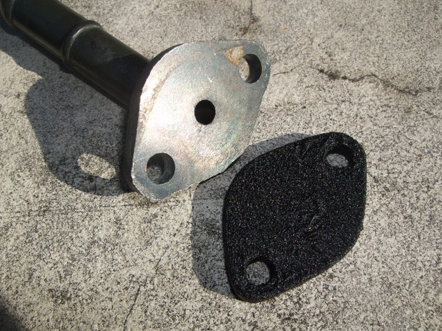
I've replaced my OEM front strut brace with a Carbing 3-point brace and the oil catch can with a Track Dog Racing oil catch so simply plugged the top of the hose with a 19mm plug. Since the OEM oil catch can oil return line is in the way for the oil filter relocation/cooler kit, I decided to remove it completely and make a blanking plate from W50mmxD3mm galvanised steel, using the OEM barb as a template:
Image


Blanking Plate painted in Wrinkle Black (rear side left unpainted):
Image


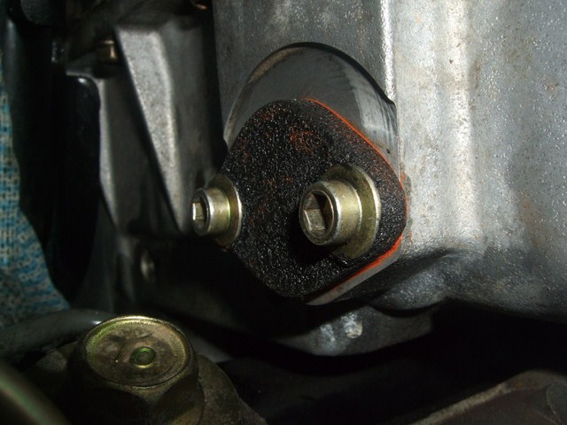
The REPCO guys recommended Loctite Copper Maxx Silicone instead of a gasket:
Image
"Hi-Temp (+316*C) RTV Silicone gasket maker.
Eight times more flexible than conventional gaskets.
Especially formulated for 4-cylinder, turbocharged or performance engines."

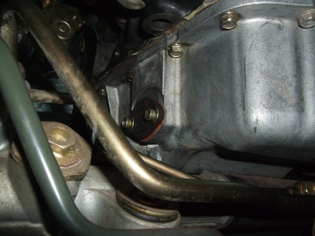
Here's the blanking plate mounted (got a bit messy with the Loctite Copper Maxx Silicon on my fingers when installing it):
Image

Image


The silicone takes 24 hours to cure fully so I figured I can take the rest of the weekend to finish the oil cooler install.

I mounted the oil filter relocation kit's engine block and can confirm that this is a real BUGGER of a job to tighten the damn thing fully, there's almost no room to wriggle a wrench in there and I needed to use locking pliers since I didn't have a wrench large enough (the GREDDY block uses something larger than 24mm - I only know this since 24mm is my largest socket size).

I also cut the stainless steel hoses to length and assembled them. The aluminium AN vice jaws make this job a LOT easier and leave the fittings undamaged - I don't recommend doing this job without them and am glad I waited for them.
Generic stainless steel hose assembly Instructions: https://www.pegasusautoracing.com/document.asp?DocID=TECH00027
AeroFLow catalog instructions (see top of page 79): http://issuu.com/aeroflow/docs/af_cat_4_web_111111/5

Tomorrow's jobs: Fit the stainless steel hoses (not looking forward to that job) and complete the oil change.


Originally posted by bootz, Sat Mar 10, 2012 10:19 pm[

Interesting to speculate that by the time you have finished with Gina she will be ready for Le Mans. :mrgreen:
Don't worry about dying, worry about not living!
Garage Thread: http://www.mx5cartalk.com/forum/viewtopic.php?f=57&t=76716

User avatar
Lokiel
Forum legend
Posts: 4126
Joined: Thu May 28, 2009 2:39 pm
Vehicle: NB SE
Location: Brisbania

Re: Lokiel's "Gina" (once a 2004 Titanium SE) Recreated AGAIN

Postby Lokiel » Tue Jun 05, 2018 7:54 pm

Originally posted by Lokiel, Sun Sep 24, 2017 4:03 pm

Originally posted by Lokiel, Sun Mar 11, 2012 8:02 pm[

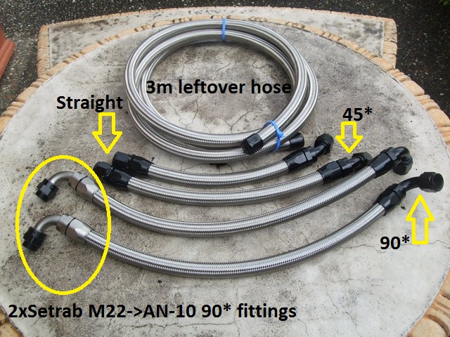
I started the hose installation today, here's the assembled hoses, along with the 3m of leftover stainless steel hose (I overestimated how much I'd need and suspected I may screw up a few times so ordered extra - never thought I'd be so efficient at assembling stainless steel oil hoses?):
Image

- apologies for the state of the outdoor setting, we had a heavy downpour shortly before this photo was taken so it looks quite grotty here.

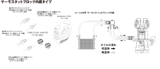
Here's the GREDDY installation instructions - kudos to the Japanese guy that drew the diagram, you don't even need to be able to read Japanese to figure out how to hook it up:
Image


The problems started pretty much straight away.

I decided to fit the hoses from the oil filter relocation block to the engine block first since the hoses on the engine block would be the hardest to get at. Unfortunately for me, stainless steel hoses don't bend much at all and the straight hose fittings I planned to mount to the engine block would not co-operate and thread onto the engine block barbs at all. The fittings are aluminium and the last thing you want to do is force these since they will cross-thread easily, not something you want on oil lines.

No worries I thought, I'll just spin the hoses around 180* and fit the 45* fittings to the engine block instead of the straight fittings. This worked a treat, it only took me about 30 minutes to get both 45* fittings temporarily screwed onto the engine block (it's REALLY awkward to get at those fittings).

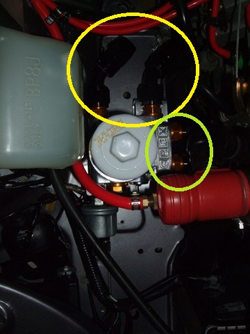
The return hose (circled in yellow on the right in the photo below) fitted perfectly, no obstructions and only needing a mild curve down to the block:
Image


Unfortunately the incoming hose on the left would not fit because of the OEM brace - this is why I needed to use the 45* connector in the first place :(. I kicked myself for not over-ruling my initial thoughts on ordering 2 additional 45* fittings in the first place just in case the straight fittings wouldn't work.

There was nothing else to do except order another two 45* fittings :evil:. I couldn't just order one and keep the straight fitting on the return hose because the two hoses would not fit onto the relocation block at the same time. The hoses themselves aren't obstructed between the blocks and don't need to bend much so stainless steel hoses are perfect for this route (ie. nothing to rub against and can be kept short).

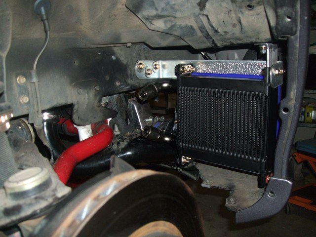
After this let-down, I started on the oil cooler hoses:
Image


There were 2 BIG problems with these hoses:

1. The 2x90* Setrab fittings are IMPOSSIBLE to thread onto the Setrab oil cooler with the stainless steel lines installed and the oil cooler mounted - the oil cooler would need to be removed and the fittings threaded onto it. Luckily I ordered 2xSetrab M22->10-AN adapters for this very reason, but not an additional 2x90* 10-AN fittings since I over-ruled myself on these too as part of the earlier decision :(. FM use these adapters on their kit and I suspect that it's for the same reason. I had to order another 2x90* 10-AN fittings.

2. The hoses need to route up into the engine bay and I intended them to do so by passing behind that brace (on top of the sway bar) in the photo above. When sizing the hoses individually, this was quite feasible, but with the two hoses fitted simultaneously there was a LOT of rubbing everywhere, which is BAD since stainless steel hoses effectively saw through whatever they touch, and the two hoses together just wouldn't flex enough. Damnit - I had to order some nylon-shielded 10-AN hose too. The nylon hose is more flexible than stainless steel braided hose and won't damage what it contacts - only ordered 2m of the stuff.

So today was pretty much wasted :(

Ah well, at least I learned 2 valuable lessons:

1. Only use stainless steel hoses if the routes don't require much hose bending and don't contact other surfaces (or can be prevented from contacting them) and

2. When fabricating a custom-kit, have as many options available on hand as you can, otherwise your project is going to be compromised or late.


Originally posted by Lokiel, Sun Mar 18, 2012 7:58 pm[

FINALLY! I finished the oil cooler install today, WooHoo! (most of it was actually done yesterday, I just had to put it all back together today).

It took a couple of tries to get the length of the filter->engine block hose lengths correct with the 2 new 45* barb fittings. Stainless steel hoses are a pain in the arse to fit if they're too long and impossible if they're too short; I had to make them slightly longer than optimal to allow me to thread the hoses onto the oil filter block - threading the barbs can be a time-consuming task. I'm happy with the final result, the hoses don't touch anything but the manifold->engine block brace will never again be installed.

I assembled the nylon hoses and noted that they're MUCH more flexible. Surprisingly I found it easier to make the Stainless Steel hoses - when you remove the tape after you've cut the nylon-covered hose, the ends fray out like an "Afro" and you need to give it a haircut - any "hairdresser car" comments will be ignored.
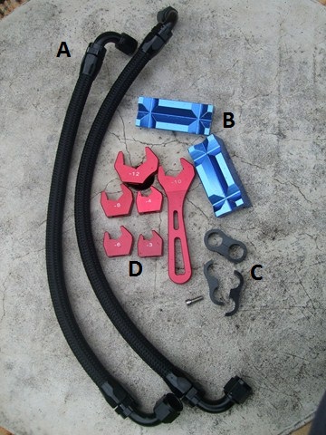
Image

A - Nylon hoses with 90* barbs
B - AN Aluminium Vice Jaws
C - Aluminium AN-10 hose separators (only used one)
D - Aluminium AN Spanner Set

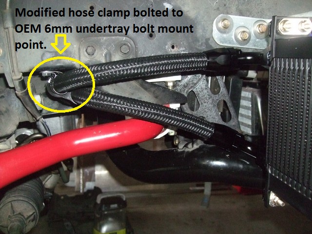
The flexibility of the nylon-clad hoses made routing the oil cooler hoses a cinch. I modified a hose clamp and bolted the top hose to the 6mm OEM undertray mount point and used a hose separator to secure the lower hose to the top hose. This keeps them separated at their closest point and ensures that the lower hose is clear of the sway bar.
Image

The clamp is not load bearing, it's there to prevent the hose from moving.

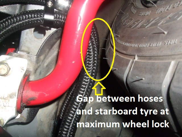
I actually had to do a minor bit of re-work with the above setup when I thought I should test whether or not the tyre would touch the hoses at maximum lock - it did so I had to tighten the hoses slightly. Now there's about 15mm of clearance, not a problem since the hoses do not move at all:
Image


The wheel liner needed to be modified to accommodate the new oil cooler hoses, here's the before and after shots:
Image

Image

As you can see, I lost a mount point in the N/W corner and one in the S/W corner but it's still held firmly in place.

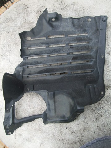
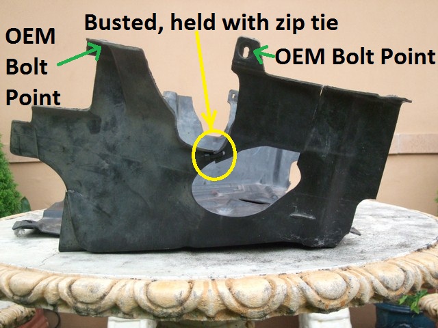
The next stage was to modify the undertray. I was already using a zip-tie to hold some of it together so wasn't too concerned about cutting it up. Here's the before and after shots:
Image

Image

That top left OEM Bolt Point is now used by my modified hose clamp to secure the top oil cooler hose.

I triple-checked/tightened everything, re-filled the oil and gave it a few test starts to check for leaks - I've heard too many horror stories of hose leaks after oil filter relocation installs. My "anality" was good so far, the engine ran smoothly with no leaks - near as I can tell, I used about 4.5L.

Here's how it looks with everything assembled - I used a zip-tie to secure the rear section of the undertray to an OEM brace to stop it flapping about:
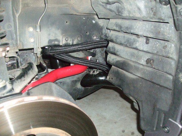
Image


I wasn't too keen on the exposed nylon hoses so clad them in some split loom (split on the underside to prevent moisture accumulation):
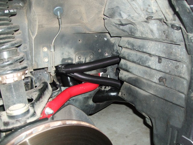
Image


Once the car was back in one piece I took it for a run, stopping regularly to check everything and going again. One thing that does concern me now is that the oil filter is now 7mm away from the radiator overflow bottle:
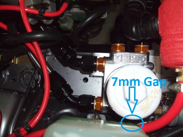
Image


The oil filter gets quite hot so will this melt the radiator overflow bottle or is there enough gap for this not to be a problem?

If it is a problem, I will need to get an aluminium unit.

Next weekend I need to install the sensors to see how effective the oil cooler is (ie. drive the car, note the temperature, stop, note the temperature change, drive and note the temperature change).
Don't worry about dying, worry about not living!
Garage Thread: http://www.mx5cartalk.com/forum/viewtopic.php?f=57&t=76716

User avatar
Lokiel
Forum legend
Posts: 4126
Joined: Thu May 28, 2009 2:39 pm
Vehicle: NB SE
Location: Brisbania

Re: Lokiel's "Gina" (once a 2004 Titanium SE) Recreated AGAIN
Postby Lokiel » Tue Jun 05, 2018 7:55 pm

Originally posted by Lokiel, Sun Sep 24, 2017 4:04 pm

Originally posted by Okibi, Sun Mar 18, 2012 11:26 pm[

Sounds like a good excuse for a nice alloy overflow bottle. :mrgreen:


Originally posted by MINX, Mon Mar 19, 2012 9:00 am[

Like mine?
Image


Originally posted by Okibi, Mon Mar 19, 2012 9:53 am[

I love yours, i'll take one! :mrgreen:


Originally posted by MINX, Mon Mar 19, 2012 10:00 am[

Okibi wrote:I love yours, i'll take one! :mrgreen:


Sure - ask here http://miataroadster.com/canton_racing_products/canton_racing_products_coolant_expansion_reservoirs/canton80276/i-464280.aspx


Originally posted by hks_kansei, Mon Mar 19, 2012 11:26 am[

Surely melting won't be an issue since it's filled with fluid?

I seem to recall a science experiment where you can boil water in a paper cup, because the cup is full of water.

Something like that, I'm not a scientist.


Originally posted by Lokiel, Mon Mar 19, 2012 2:30 pm[

A reservoir like this Weapon R Coolant Reservoir on the left would look even cooler, AND it has a level meter:

Image

- doubt it would fit though :(


Originally posted by bruce, Mon Mar 19, 2012 2:51 pm[

You could try hiding the coolant reservoir (like Okibi was thinking).
Or just shove a bit of insulating material in between.
Or maybe not worry about it (I don't think the plastic would melt - it's used to engine bay temps).


Originally posted by bootz, Mon Mar 19, 2012 6:19 pm[

The amount of time and work taken qualifies this to be an ubercooler. :beer:
Don't worry about dying, worry about not living!
Garage Thread: http://www.mx5cartalk.com/forum/viewtopic.php?f=57&t=76716

User avatar
Lokiel
Forum legend
Posts: 4126
Joined: Thu May 28, 2009 2:39 pm
Vehicle: NB SE
Location: Brisbania

Re: Lokiel's "Gina" (once a 2004 Titanium SE) Recreated AGAIN
Postby Lokiel » Tue Jun 05, 2018 7:55 pm

Originally posted by Lokiel, Sun Sep 24, 2017 4:05 pm

Originally posted by Lokiel, Sun Mar 25, 2012 10:15 pm[

I spent Saturday running errands, taking care of my neglected hedges which have gone berserk with the rain we've had, so didn't get time to do much work on the car. It was great to actually drive the car again and some of my errands took much longer than expected because I took the long way everywhere just to enjoy the drive.

Today I planned to get the wiring done for the PLX oil pressure+temperature and water temperature sensor modules.

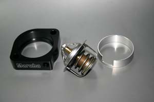
About a year ago I bought the Maruha 78Thermostat and Water Temperature Sensor Adapter kit in preparation for this:
Image
See http://www.maruhamotors.co.jp/miata/parts/watertempsensor.html

The problem with the adapter was that it too had a BSPT-28 thread so I tapped that out to an NPT-27 thread to match the PLX sensor. I'm not worried about leaks because I had to tap quite deep into the adapter for the sensor to go in as far as I wanted and it was originally only tapped to a shallow depth. I'm actually going to use the Loctite Copper Maxx Silicone instead of a thread sealant since it is sensor-safe which should seal the threads well enough.

There are 7 wires in total that need to be routed from the engine bay sensors to the PLX sensor modules, 2 per sensor and a 3rd for the oil pressure alarm indicator. The firewall hole that most people use to route the boost hose through was not going to accommodate 7 additional wires so I decided to use the symmetrical one on the other side of the engine bay; this isn't a bad option since the sensor modules are going to be mounted on that side in the passenger cabin anyway. The problem with this firewall hole is that it's a pain in the butt to route wires through because you first need to punch a hole through the firewall padding which has a hard covering over top of the wadding, then you need to remove the blower unit and cooling unit under the dashboard so you can see where the hell the wire threaded through the firewall hole went (it tends to get tangled up somewhere behind these units and you can't see where it's gone).

I figured I'd get all the interior ripped out, including the blower unit and cooling unit, in the morning and finish the wiring in the afternoon. I'd been warned that removing these units was a pain and that I'd need to remove the passenger side airbag which concerned me since I was wary of marring the dashboard and of the airbag blowing my head off.

I removed all nuts/bolts I could see on the blower unit but it was still firmly in place. After consulting the MAZDASPEED Tech Guides, I saw that there was another nut on top of the unit and found the only way to access it was by removing the passenger-side airbag - "Ah, that's why everyone told me the airbag needed to be removed!".

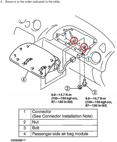
Removing the passenger-side airbag was a pain:
Image

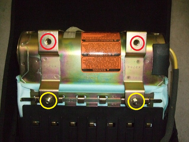
There are 2 nuts, tagged as "2" in the above picture and 2 bolts, tagged as "3" in the above photo, that need to be removed to slide out the airbag module. The two mounted bolts that the front nuts connect to must be pushed up and out of the airbag brackets to allow the module to slide out. These kept slipping back into their brackets :( I ended up shoving 2 screwdrivers in the rear bolt hole brackets which lifted the airbag module enough to slide it out.

The red-circled threaded bracket holes are the rear of the airbag module; the yellow-circled mounted bolts were the bolts that needed to be pushed up to slide out the airbag module:
Image


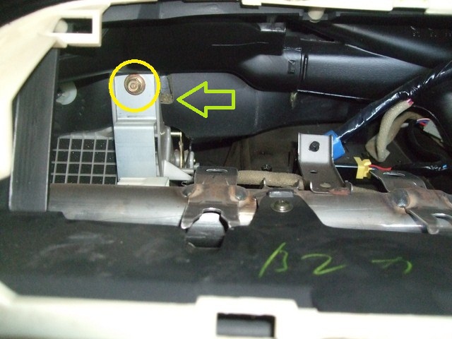
The photo below shows the top blower unit nut, circled, that needs to be removed and the depth of the firewall padding, pointed to by the arrow, that needs to be cut through to thread the wiring:
Image


Once this was done I pushed a coathanger through the firewall hole to see where it came out and found that I didn't need to remove the blower and cooling units completely, there was enough play in the blower unit to be able to reach the coathanger and direct it where I needed.

After several attempts to pull the wires back up through the firewall from the footwell, it became apparent that there was no way I was going to be able to get all 7 wires through at once and even individually I couldn't get more than 2 through. I taped the 7 wires together, spiral twisted them together to get some rigidity and pushed them through the firewall from the engine bay - this worked great and I kicked myself for not doing it earlier.

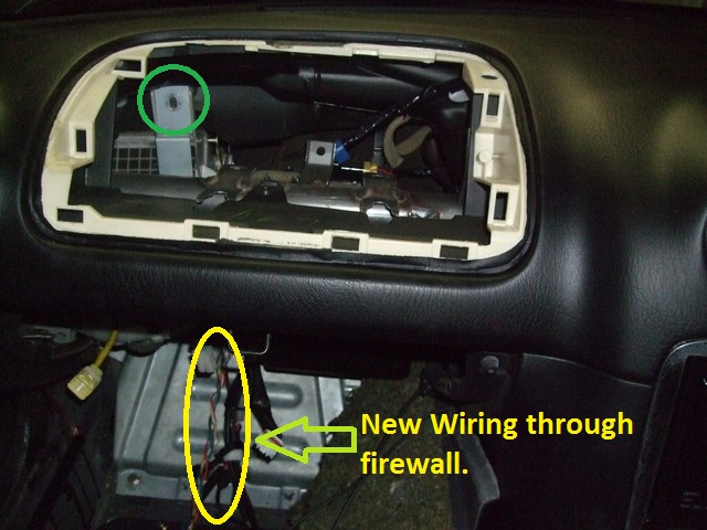
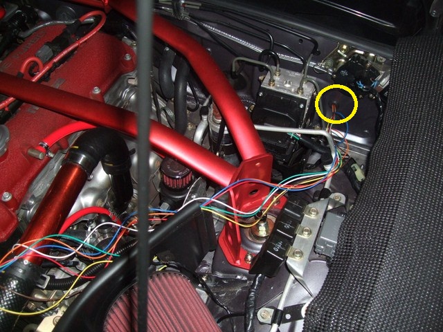
Circled ("elipsed" if you're pedantic) in yellow below are the new wires:
Image


After looking through my stock of grommits to fill out the firewall hole and protect the wires, I realised I could simply drill a hole in the OEM firewall plug/grommit to thread the wires through - it was practically made for it:
Image


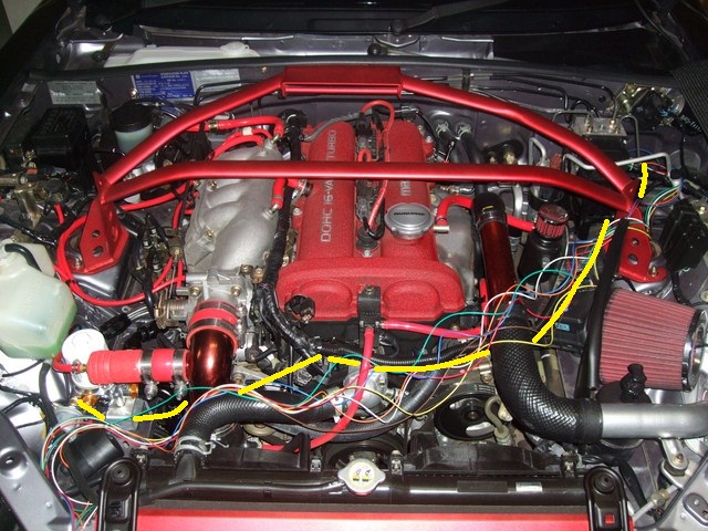
The yellow line below shows my proposed wire routing which will be clad in split loom. The split loom in front of the engine, above the yellow line will be replaced with a longer loom that extends to the firewall. There will be a second split-loom section that extends from the sensors on the left to the right hand side of that 3rd line from the left. This should keep it all nicely shielded and "invisible":
Image


So much for getting it all done in the afternoon!

Unfortunately I probably won't be able to do much until next weekend, which is when I planned to install the Maruha adapter and replace the Innovate LC-1 with the PLX Wideband sensor - the rest should be a cinch?
Don't worry about dying, worry about not living!
Garage Thread: http://www.mx5cartalk.com/forum/viewtopic.php?f=57&t=76716


Return to “MX5 Garage Chat”

Who is online

Users browsing this forum: No registered users and 106 guests