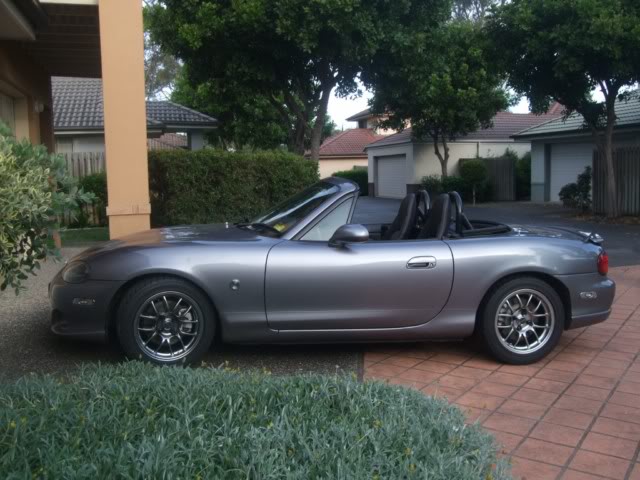
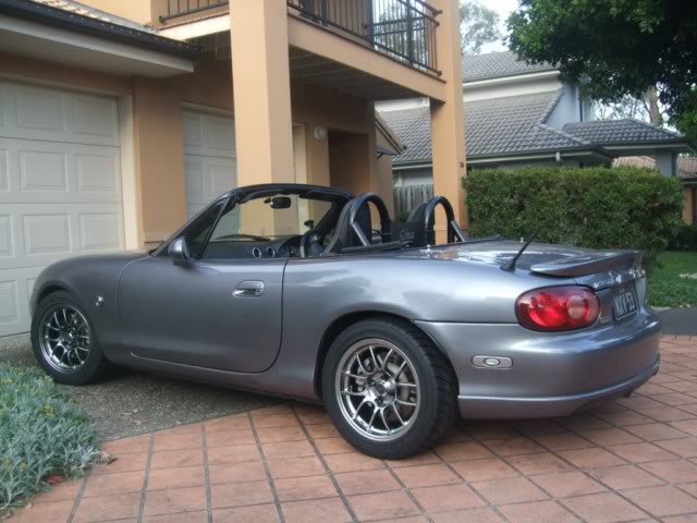
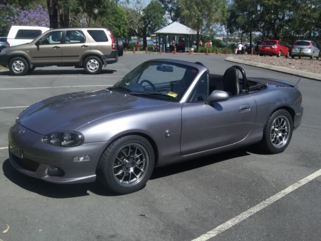
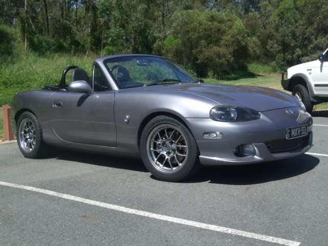
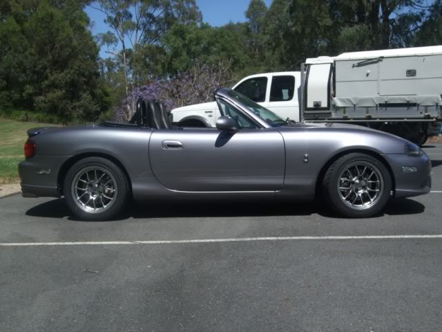
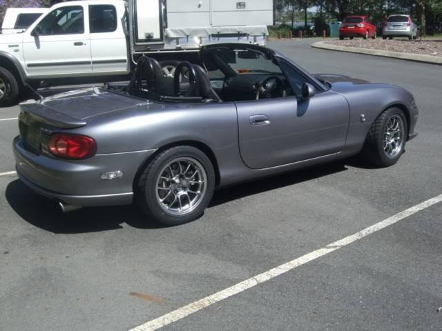
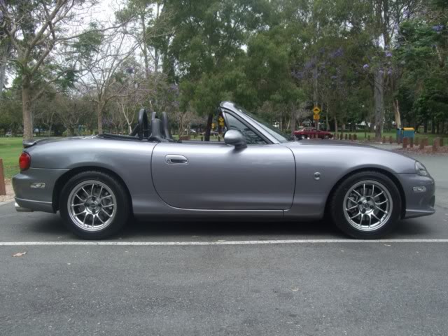
Lokiel's "Gina" (2004 Titanium SE)

Chat to do with your MX5/Miata/Eunos Garage Ride(s).

Moderators: timk, Stu, zombie, Andrew, The American, Lokiel, -alex, miata, StanTheMan, greenMachine, ManiacLachy, Daffy

User avatar
Lokiel
Forum legend
Posts: 4126
Joined: Thu May 28, 2009 2:39 pm
Vehicle: NB SE
Location: Brisbania

Re: Lokiel's "Gina" (once a 2004 Titanium SE) Recreated AGAIN

Postby Lokiel » Tue Jun 05, 2018 7:37 pm

Originally posted by Lokiel, Sun Sep 24, 2017 3:34 pm

Originally posted by Lokiel, Sun Oct 31, 2010 10:47 pm[

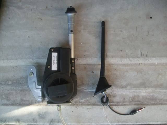
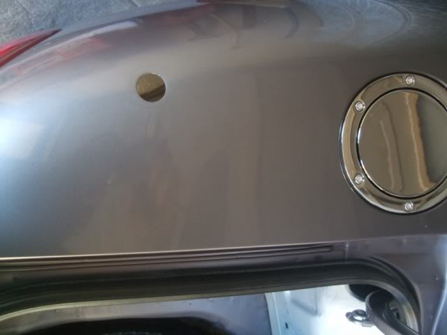
I never liked the OEM antenna, it's too big and my Pioneer head unit seems to think it must be up if I'm using USB/iPod input so the damn thing is up most of the time. The Shark Attack II fixed antenna from Lo Custom looks almost OEM so I decided to install it (see http://www.locustom.com/miata_fender_install.htm).

Here's what the OEM antenna unit looks liked compared to the Shark Attack II:
Image

Got rid of some weight there too - a nice bonus.

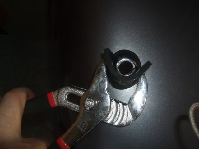
The Lo Custom instructions state "Remove the factory power antenna by removing the external mast fastening nut and the 10mm nut on the bracket. Unplug the antenna cable and the wiring harness". Unfortunately they didn't say how to remove the external mast fastening nut and I was paranoid about scratching the paint. In the end it turned out to simple using a strip of rubber and wide-jawed pliers, the external nut came off quite easily:

Image

Image


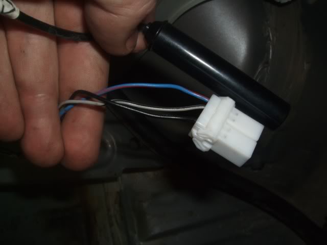
Here's a closeup of the car's antenna and power connectors; the Shark Attack II's power wire must be connected to the 12V power pin, which is the middle grey/black wire:
Image


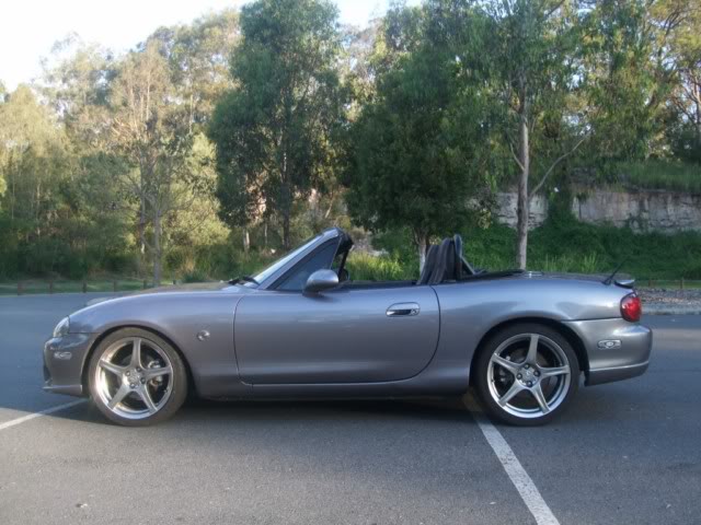
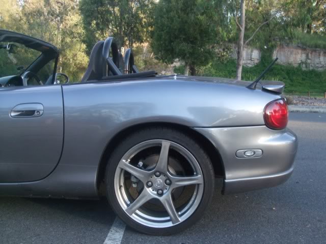
And here's what it looks like installed:
Image

Image


Radio reception is just as good as the original antenna.
Don't worry about dying, worry about not living!
Garage Thread: http://www.mx5cartalk.com/forum/viewtopic.php?f=57&t=76716

User avatar
Lokiel
Forum legend
Posts: 4126
Joined: Thu May 28, 2009 2:39 pm
Vehicle: NB SE
Location: Brisbania

Re: Lokiel's "Gina" (once a 2004 Titanium SE) Recreated AGAIN

Postby Lokiel » Tue Jun 05, 2018 7:37 pm

Originally posted by Lokiel, Sun Sep 24, 2017 3:35 pm

Originally posted by Lokiel, Wed Nov 03, 2010 7:19 pm[

The 6ULs I pre-ordered over 2 months ago have FINALLY arrived and I had them fitted today - WOO HOO!!!

Here's a couple of preliminary shots taken around 5:30pm, just after taking it for a spin and before it got too dark:

Image

Image


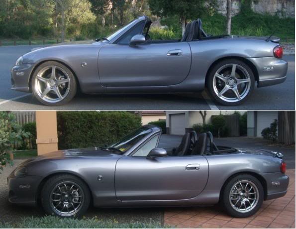
Rims: Nickel 15x8 6ULs
Lug Nuts: Black 949racing
Tyres: Toyo Proxes R1R 225/45/15
Alignment: FM alignment - see http://www.flyinmiata.com/tech/alignment.php

Initial Impression: It's going to take me a while to get used to the new look. I'm glad I previously installed the BC Coilovers and lowered the car to avoid the "4WD look" when you drop rim size and increase the sidewall. The ride is MUCH softer in terms of soaking up the bumps which is what I wanted but the steering is not as sharp - obviously due to the new sidewall width and tyre flexing. A side-effect of the sticky tyres that I wasn't expecting was that they pick up a lot of gravel that gets shed in the wheel well - it gets quite noisy.


Originally posted by Lokiel, Sat Nov 06, 2010 1:36 pm[

Took some photos of the new 6UL 15x8 "shoes" today:

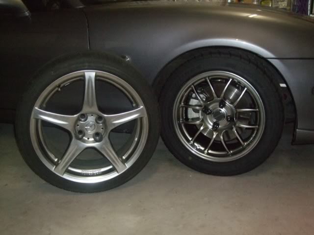
Original 17x7 Racing Harts vs 949racing 6UL 15x8s:
Image


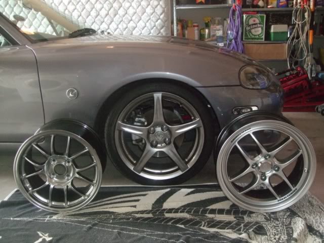
949racing 6UL 15x8s vs Racing Hart 17x7s vs Enkei SC14 16x7:
Image


17x7 Racing Harts vs 949racing 6UL 15x8:
Image


Image

Image


Alas, stupid truck that pulled up in the background while I was taking photos:
Image

Image


For additional offset/guard photos, see http://mx5cartalk.com/forum/viewtopic.php?f=30&t=33060&start=255


Originally posted by Lokiel, Sun Nov 14, 2010 12:13 pm[

I installed my Flyin' Miata Frame Rails yesterday with the help & guidance from Stuart/MINX - first time I've ever installed anything in the car without referring to instructions while doing a job. It's a big help just having a second set of hands to hold the bolts in place on top when tightening the nuts from underneath so thanks a lot for that Stuart.

One "gotcha" to be aware of when installing the frame rails is that the two pre-drilled frame rail holes in the driver's side brace that are used to support the brake line bracket are too small for the supplied screw so should be drilled out to the correct size prior to installation. The frame rails are stainless steel too so this is pretty tough on drill bits - I'd hate to do it with them installed on the car and the drill bit gets red hot.

The frame rails really work well. When using the scissor jack under the front pinch weld to allow me to remove my main jack from the front, the only wheel touching the ground was the opposite rear wheel (the other rear wheel was substantially airborne). I'd have no hesitation about jacking one side of the car up in the middle of the frame rail.


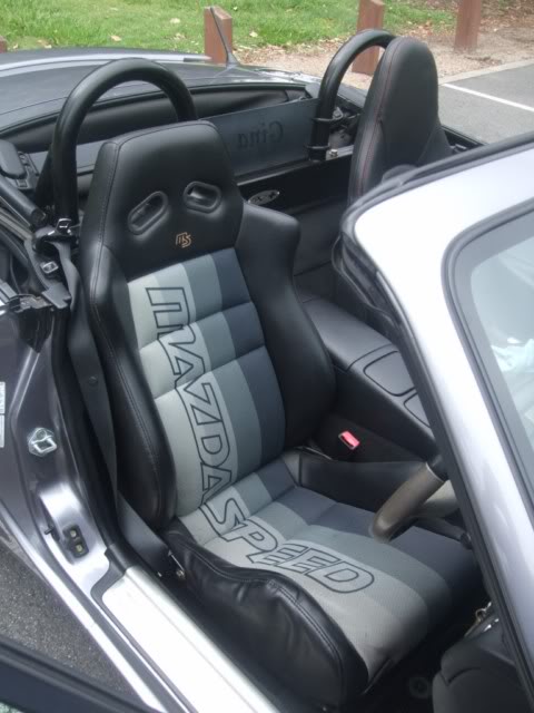
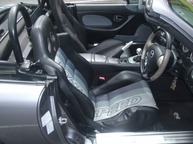
Since the seats needed to be removed for the job, I'd purchased a Black MazdaSpeed seat from Rupewrecht (see http://www.astinagt.com/forums/showthread.php?s=8fc70e75b2a2f35d75503948322067da&t=10668 ) that I installed yesterday too. After coming from a Mitsubishi Starion, who's seats had 7 different adjustments, I was never happy with the OEM seat's lack of lumbar and lateral support, especially on long drives. I didn't want racing seats because they're a bugger to get in and out of and the MazdaSpeed seats didn't look as cumbersome (plus they go really well with my re-coloured door trim and remove the "too-much black" look of the interior).

The seat was 2nd hand from Japan and one side of the seat cushion was a little crushed from entering and leaving the seat I assume (this was mentioned in Rupewrecht's site). Rupewrecht actively "trolls" the Japan Yahoo auction site and imports goods so it's worth looking at his site from time to time and let him know if you're looking for anything special - Yahoo Japan is all in Japanese and many sellers won't sell O/S (possibly due to language issues) so Rupewrecht is a great middle-man and usually responds to requests within a day.

Here's what the seat looks like installed (you can see the crushed side cushion):
Image

Image


Normally I'd have the seat belt over the right lateral wing but moved it aside for these shots.

I really need to get the steering wheel re-trimmed now to German Grey to match the door trim and seat better. Does anyone know a trimmer in Brisbane who can do this?

Here's a profile showing the height of the MazdaSpeed seat vs the OEM seat (and the Nickel 6ULs which took FOREVER to arrive):
Image


The seat is very snug when you first sit in it. After about a minute or two it gets much more comfortable as you settle into the seat and you really feel the lateral and lumbar support hugging you in. The seat's outer "wings" under the thighs are a little too tight though and I'm hoping that they'll reform under my weight to a more comfortable position - they really don't need to be that high and I prefer the shallower OEM seats in that aspect. It's not as easy to get in and out of as I'd hoped (the driver-side thigh "wings" is the issue - it shouldn't be that high) but I don't think it's as bad as a racing seat.

At its lowest point, the seat sits lower than the OEM seat but it angles upward toward the front so seems higher.
Don't worry about dying, worry about not living!
Garage Thread: http://www.mx5cartalk.com/forum/viewtopic.php?f=57&t=76716

User avatar
Lokiel
Forum legend
Posts: 4126
Joined: Thu May 28, 2009 2:39 pm
Vehicle: NB SE
Location: Brisbania

Re: Lokiel's "Gina" (once a 2004 Titanium SE) Recreated AGAIN

Postby Lokiel » Tue Jun 05, 2018 7:38 pm

Originally posted by Lokiel, Sun Sep 24, 2017 3:36 pm

Originally posted by Lokiel, Sun Nov 21, 2010 8:04 pm[

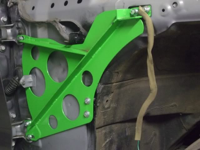
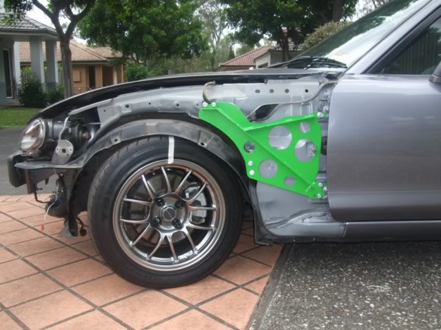
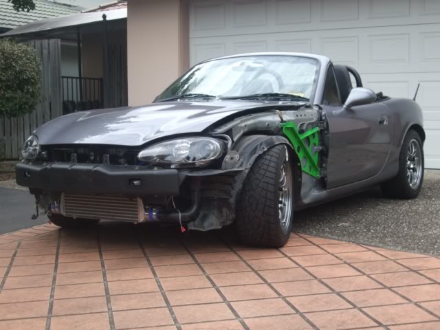
I installed my Boss Frog "Frog Arms" on the weekend.

The Boss Frog instructions aren't too bad but are generic so I did a bit of web-surfing to find out what "gotchas" there may be associated with an NB installation. The "Boss Frog Frog Arms Installation Thread" on miata.net (see http://forum.miata.net/vb/showthread.php?t=332166&highlight=frog ) is a pretty good resource for this. Many mentioned that it's not necessary to remove the front bumper assembly - unfortunately this was not the case for me :( so I updated the thread (see #129) to describe why and what I needed to do (ie. it's a useful guide to removing the front fenders on an NB).

Image

Image


I just like this photo since Gina has never been this "nekked" before:
Image


The install took a lot longer than I'd hoped because:
1. I'd never removed the fenders before and had to figure out how to do it (no "Idiot's Guide" on the web for an NB),
2. I had to remove that bloody front bumper AGAIN! (I spent a LONG time trying to avoid the need to remove it before giving up and just doing it),
3. There is some grinding/cutting required,
4. I had to wait for the rust-proofing to dry,
5. I got really hungry and needed to cook a decent meal,
6. I HAD to watch the end of the movie I started watching while cooking and eating lunch,
7. Adjusting the doors takes a few trial and error attempts (the car needs to be level and supported on its wheels to do this properly so you need to put the wheels back on and take it off the stands and jack) and
8. You need to jack the car up again, put it on stands, and remove the wheels to complete the fender installation.

The Frog Arms do make a difference to the chassis front rigidty and are definitely worth the effort to install them. I recommend that you read the miata.net thread too if you're planning to install them (especially my comment regarding the need to purchase 6 larger washers for the door bolts since the Boss Frog door washers aren't big enough).
Don't worry about dying, worry about not living!
Garage Thread: http://www.mx5cartalk.com/forum/viewtopic.php?f=57&t=76716

User avatar
Lokiel
Forum legend
Posts: 4126
Joined: Thu May 28, 2009 2:39 pm
Vehicle: NB SE
Location: Brisbania

Re: Lokiel's "Gina" (once a 2004 Titanium SE) Recreated AGAIN

Postby Lokiel » Tue Jun 05, 2018 7:38 pm

Originally posted by Lokiel, Sun Sep 24, 2017 3:37 pm

Originally posted by bootz, Sun Dec 12, 2010 6:12 pm[

The Nickel 6ULs are so cool. 8)
and is that a JDM s/steel handbrake & gearknob?
You will have to spill the fender removal secret :lol:


Originally posted by Lokiel, Wed Dec 15, 2010 2:37 pm[

bootz wrote:The Nickel 6ULs are so cool. 8)
and is that a JDM s/steel handbrake & gearknob?
You will have to spill the fender removal secret :lol:


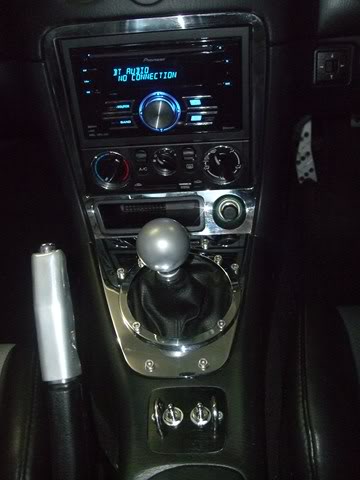
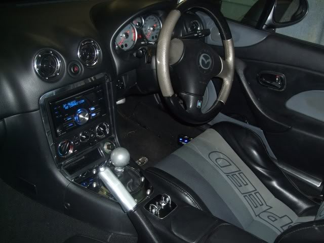
The gear knob and handbrake lever are chrome Voodoo pieces. Voodoo chrome handbrake levers seem to come and go; sometimes every vender has them, other times nobody has them so if you want one you may have to wait a while. The handbrake lever is nice and chunky; every other one I've tried since seems too thin now.

I'd actually recommend the Pearl Voodoo knob over the chrome one. Initially the chrome knob used to blind me since it's round and managed to reflect directly into my eyes whenever there was direct sunlight on it.It's now dulled to a pearl finish, I assume due to oil from my hand, so no longer reflects sun into my eyes - I don't polish it since I prefer the "pseudo-Pearl" finish.

See http://forum.miata.net/vb/showthread.php?t=402640&highlight=nb+fender for NB fender removal information. I created this as a new thread since it's buried in the Frog Arms installation thread - the information is now easier to find in its own dedicated thread when using miata.net's search function.


Originally posted by bootz, Wed Dec 15, 2010 10:09 pm[

Fender removal thread very well put together, thanks.


Originally posted by bootz, Fri Dec 24, 2010 1:36 am[

Lokiel wrote:After driving around a week with my new BC coilovers, I developed an irrational fear of speed humps after the rear bottomed out on a few of them so I decided to raise the rear end 0.5" above the front as recommended by Davex3 (Keith Tanner from FM recommends 0.5", ranging from 12" front and 12.5" rear to 12.5" front and 13" rear).

When I installed the coilovers, I left them at their original settings since I'm going to replace the rims+tyres soon anyway and didn't want to waste time "dicking about" with them too much. The original settings were in fact Front: 315mm(12.4"), Rear:310mm(12.2") so the rear WAS too low as pointed out above.

Since I was happy with the front I adjusted the rears to 327mm(12.7") - or damn close to that.


The positive comments owners are saying about BC coilovers!
Could you tell me where the measurements that you describe are taken from. I'm assuming its from the ground to somewhere on the suspension??


Originally posted by Lokiel, Fri Dec 24, 2010 12:44 pm[

The ride height measurements are taken from the centre of the wheel hub to the highest point of the fender's wheel arch (not the highest point in the wheel well) when the car is supporting its own weight (ie. the car is not on stands or a jack).

This measurement represents the "settled height" of the car on the shock absorber's springs.

Not sure why people don't just measure from the ground to the top of the fender's wheel arch - just a convention I guess?


Originally posted by NMX516, Fri Dec 24, 2010 6:20 pm[

Lokiel wrote:Not sure why people don't just measure from the ground to the top of the fender's wheel arch - just a convention I guess?


Because different wheel and tyre sizes, plus tyre pressures etc etc will vary the results. The measurement between centre of the wheel and top of the wheel arch is always reliant on the suspension height, which is what you're measuring. It's a consistent, reliable method of comparing ride heights.


Originally posted by Lokiel, Fri Dec 24, 2010 11:47 pm[

Thanks for that - pretty obvious now that you've explained it Image
Don't worry about dying, worry about not living!
Garage Thread: http://www.mx5cartalk.com/forum/viewtopic.php?f=57&t=76716

User avatar
Lokiel
Forum legend
Posts: 4126
Joined: Thu May 28, 2009 2:39 pm
Vehicle: NB SE
Location: Brisbania

Re: Lokiel's "Gina" (once a 2004 Titanium SE) Recreated AGAIN

Postby Lokiel » Tue Jun 05, 2018 7:38 pm

Originally posted by Lokiel, Sun Sep 24, 2017 3:37 pm

Originally posted by Lokiel, Sun Dec 26, 2010 12:09 pm[

After I pre-purchased my Frog Arms from Good-win Racing, Brian went out of his way to repackage them into a smaller box and used an alternate delivery service which saved US$203 in shipping, leaving me with that in credit (the original Boss Frog packaging must have been way over the top for it to account for that much difference).

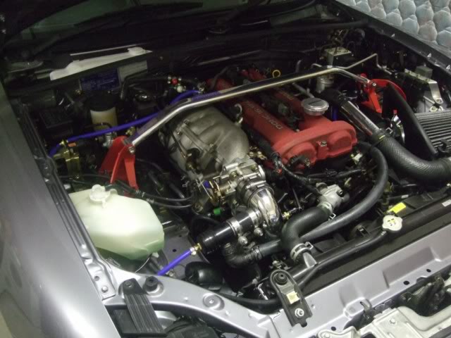
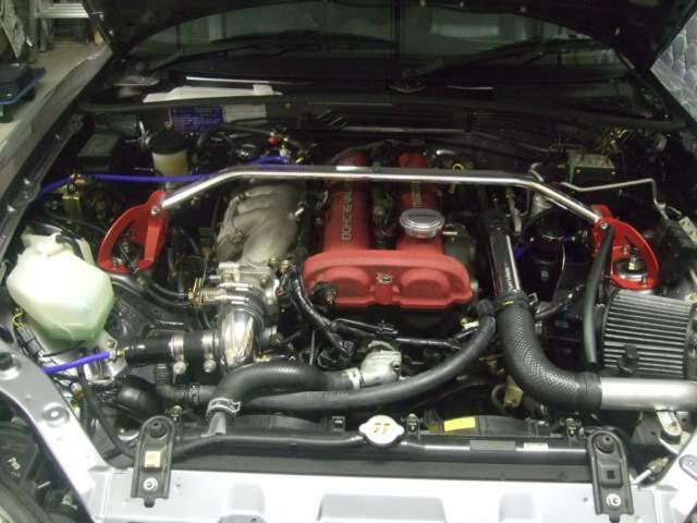
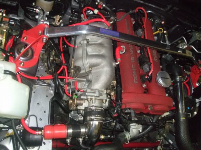
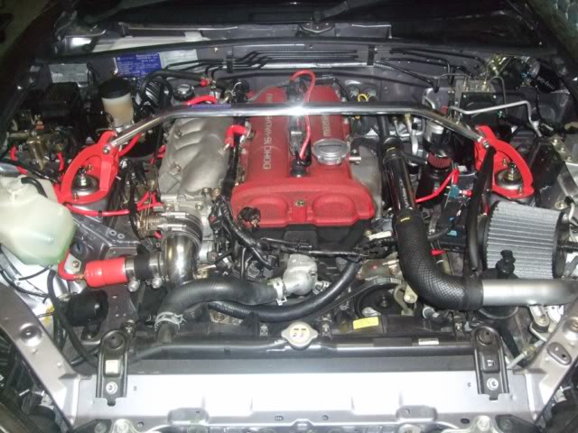
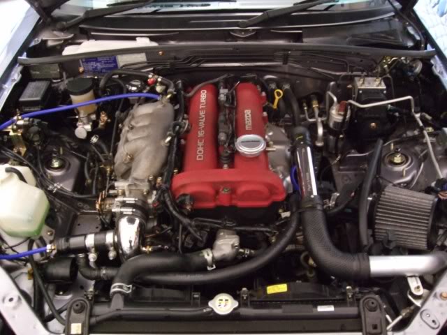
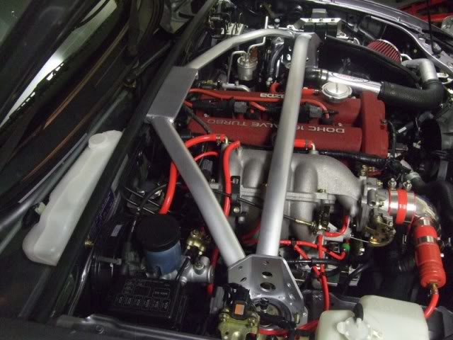
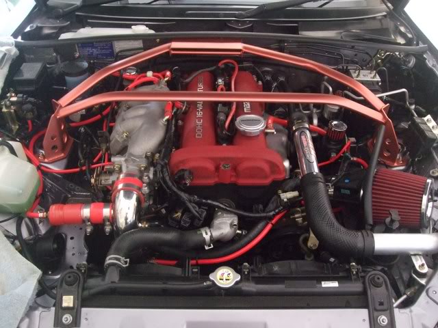
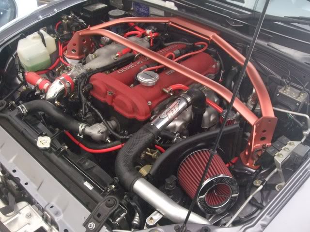
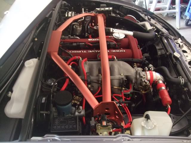
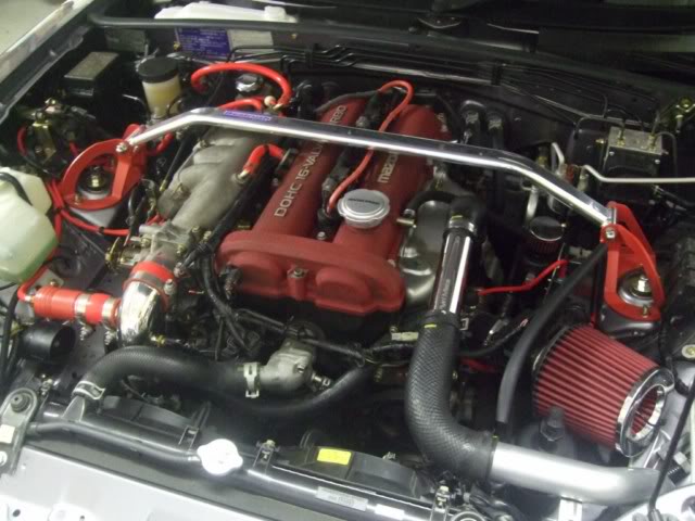
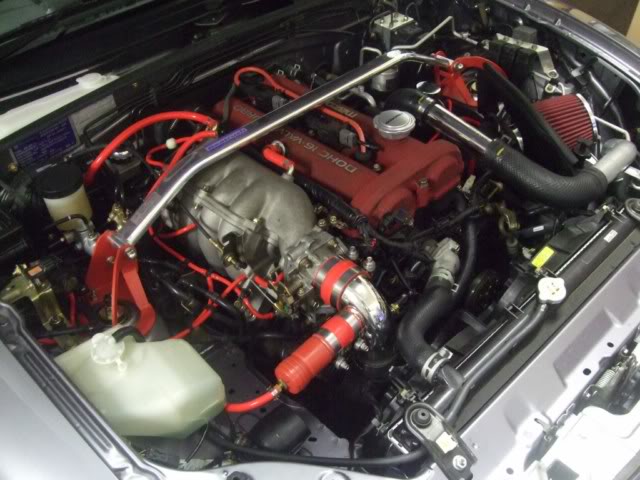
I didn't really need anything but have wanted to replace my blue silicon hoses for a while now since they look out of place in the engine bay so I ordered some RED ones to match the rocker cover and my front strut brace - it's Xmas time too so they make great Xmas decorations (the bonus being that I don't have to waste time pulling them down after Xmas) . I also orderd the Magnecor KV85 Ignition Wires to make up the difference - they come in RED too!

Here's what the engine bay looked like originally, I really didn't like those blue silicon hoses:
Image

Image


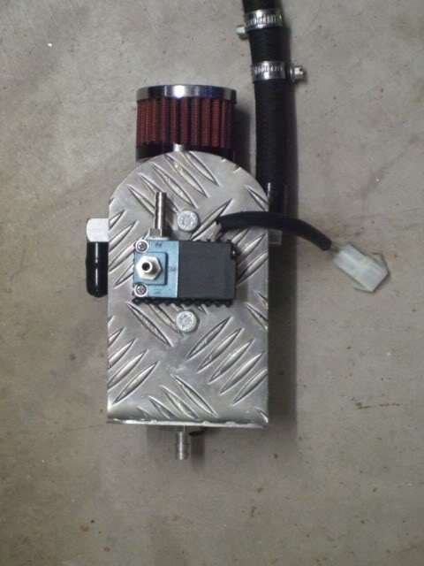
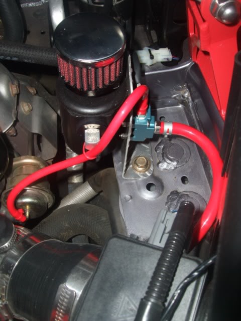
When I was doing the "hot-side" air hoses, I realised that the rear of my DIY oil catch-can bracket would make a perfect place to mount the EBC's solenoid - initially I just put a rubber pad behind it and zip-tied it to the strut tower brace so it was a bit "dodgy":
Image


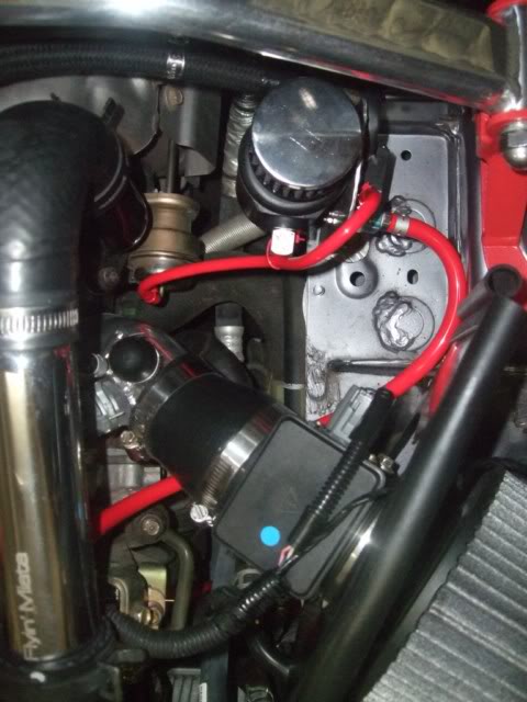
Here's the "hot-side" red silicon air hoses connected to the EBC solenoid:
Image

Image


After updating the "cold side" air hoses:
Image


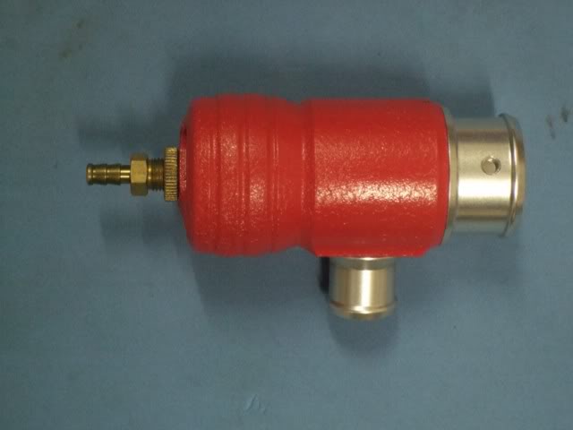
Looking at the engine bay once I'd finished, I thought to myself "Hmmmm, I still have that can of Wrinkle Red spray, I wonder what the black GFB BOV would look like in red?" Well, it looks like this:
Image

Image


While I had the BOV off, I decided to re-route the BOV's blow-off hose to tuck it out of view (see top 2 photos of this post). Previously I routed it in front of the TBI and on top of the driver-side radiator fan. Now I've tucked it behind the TBI and underneath the radiator hose - much neater:
Image


Now I think I need to find a red silicon hose to fit between the BOV and TBI and a red air filter to complete the "red theme".


Originally posted by bootz, Tue Dec 28, 2010 1:10 pm[

That is a damn nice looking engine bay.
Don't worry about dying, worry about not living!
Garage Thread: http://www.mx5cartalk.com/forum/viewtopic.php?f=57&t=76716

User avatar
Lokiel
Forum legend
Posts: 4126
Joined: Thu May 28, 2009 2:39 pm
Vehicle: NB SE
Location: Brisbania

Re: Lokiel's "Gina" (once a 2004 Titanium SE) Recreated AGAIN

Postby Lokiel » Tue Jun 05, 2018 7:39 pm

Originally posted by Lokiel, Sun Sep 24, 2017 3:38 pm

Originally posted by Lokiel, Thu Dec 30, 2010 8:03 pm[

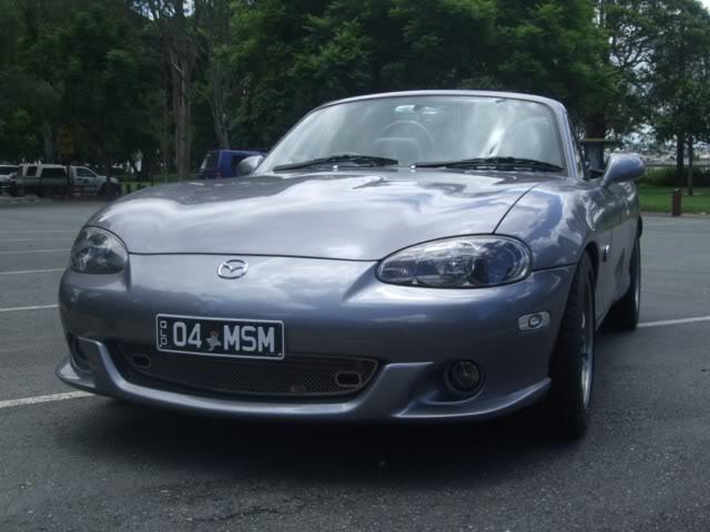
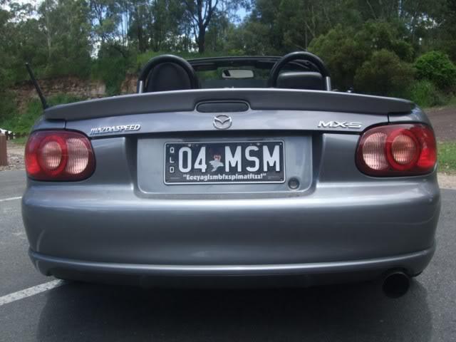
I've had these new plates on my car for a while now, but unfortunately the crappy weather has prevented me from taking any photos until now:

Image


Image


- in case you can't really see him, that's "Taz" (Warner Brother's Tasmanian Devil) on the number plate.

FYI: In the US, the SE is known as the Mazdaspeed Miata (MSM). Due to our regulators here, which deem that "speed" or "racing" badging promotes reckless driving, it couldn't be called that here and was re-designated the "SE" (in the US, there is also an "SE", a non-turbo model, which leads to some confusion). Toyota Racing Division got around this by simply using the initials "TRD" which I can't help but read as "TuRD" when I see it - I've got a mate who gets really pissed off that I always refer to his "pride and joy" Supra as "The TuRD" :mrgreen:

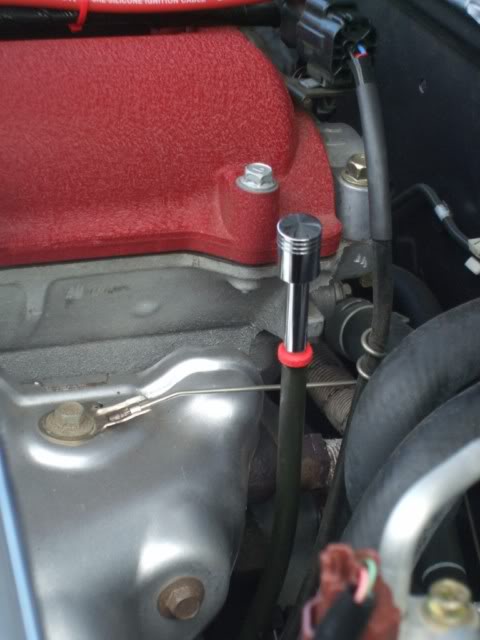
I hated the tacky plastic yellow dispstick which looks so out of place in our engine bays - what other components are yellow besides stickers and wires? Here's an old photo with the front strut brace removed that shows you what I mean:

Image


I was thinking about replacing it with this one from I.L. Motorsport:

Image

The problem is that this one costs almost 20 British pounds and I didn't feel that strongly about it - for that money I'd prefer to just break out the Wrinkle-Red spray can again! While I was at Supercheap, I spotted a pair of chrome piston-style old-school door lock knobs and thought "They'd look cool as a dipstick knob!" so I bought them (about $15). I cut and filed the dipstick handle as shown in the picture above, stuck a soldering iron down the piston shaft to get it really hot to expand it a bit, then using pliers and a hammer, tapped the dipstick into the shaft so that it's really tight. This left a bit of the yellow plastic still visible so I "fixed that" with my "good old can" of Wrinkle-Red spray (sure am geting my money's worth out of that can). It looks pretty "schmick" I reckon:

Image


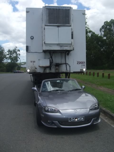
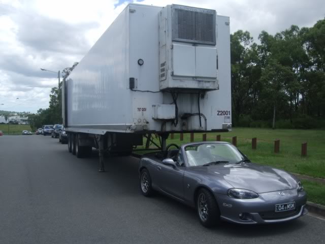
I'm planning on doing a trip up the QLD coast early next year and figured I might need to take a bit more stuff than will fit in the car so decided to "size up" some trailers:

Image

Image


- might need a little bit more grunt though?


Originally posted by bootz, Tue Jan 11, 2011 4:18 pm[

bootz wrote:
Lokiel wrote:After driving around a week with my new BC coilovers, I developed an irrational fear of speed humps after the rear bottomed out on a few of them so I decided to raise the rear end 0.5" above the front as recommended by Davex3 (Keith Tanner from FM recommends 0.5", ranging from 12" front and 12.5" rear to 12.5" front and 13" rear).

When I installed the coilovers, I left them at their original settings since I'm going to replace the rims+tyres soon anyway and didn't want to waste time "dicking about" with them too much. The original settings were in fact Front: 315mm(12.4"), Rear:310mm(12.2") so the rear WAS too low as pointed out above.

Since I was happy with the front I adjusted the rears to 327mm(12.7") - or damn close to that.


So reading this are you happiest with 12.4 frt and 12.7" rear


Originally posted by bootz, Tue Jan 11, 2011 4:20 pm[

Lokiel wrote:After driving around a week with my new BC coilovers, I developed an irrational fear of speed humps after the rear bottomed out on a few of them so I decided to raise the rear end 0.5" above the front as recommended by Davex3 (Keith Tanner from FM recommends 0.5", ranging from 12" front and 12.5" rear to 12.5" front and 13" rear).

When I installed the coilovers, I left them at their original settings since I'm going to replace the rims+tyres soon anyway and didn't want to waste time "dicking about" with them too much. The original settings were in fact Front: 315mm(12.4"), Rear:310mm(12.2") so the rear WAS too low as pointed out above.

Since I was happy with the front I adjusted the rears to 327mm(12.7") - or damn close to that.


So reading this are you still happiest with 12.4" frt and 12.7" rear?


Originally posted by Lokiel, Tue Jan 11, 2011 5:10 pm[

bootz wrote::
So reading this are you still happiest with 12.4" frt and 12.7" rear?


I have remained at this height but should probably go up to 12.5" and 12.9" since there is still one speed bump I have to go slowly over and on an angle (it's in my townhouse complex damnit - occasionally I forget and drag over it :evil:).
Don't worry about dying, worry about not living!
Garage Thread: http://www.mx5cartalk.com/forum/viewtopic.php?f=57&t=76716

User avatar
Lokiel
Forum legend
Posts: 4126
Joined: Thu May 28, 2009 2:39 pm
Vehicle: NB SE
Location: Brisbania

Re: Lokiel's "Gina" (once a 2004 Titanium SE) Recreated AGAIN

Postby Lokiel » Tue Jun 05, 2018 7:39 pm

Originally posted by Lokiel, Sun Sep 24, 2017 3:38 pm

Originally posted by Lokiel, Sat Feb 05, 2011 11:09 pm[

As part of my engine bay's "red air hose theme", I wanted to replace the drab grey AEM air filter with a red one:

Image


Originally I looked at a K&N air filter but that wasn't red enough and where I needed to drill a hole to insert the air temperature sensor was hard plastic rather than soft rubber so I would have needed to fix a rubber grommit on the opposite side to hold the sensor firmly in place (The AEM filter's "cap" is rubber and the air temperature sensor is simply forced through a small hole in the centre which holds it securely in place). At ~$130 for the K&N filter, I decided to see what other options existed.

While searching eBay I found the 3A Racing filter which had an interesting link from Auto Salon Magazine, Issue 51, January 2007 that compared many of the leading air filters, including the 3A Racing air filter, K&N filter and AEM filter. See http://www.australianauto.com.au/HTML/Images/Air%20Filter%20Shoot%20Out.pdf

It was surprising to see how badly the AEM filter rated with regard to air flow against the other filters. The 3A Racing filter was ranked 2nd in filtration and 1st in air flow so I figured that had to be worth a few extra "killer-wasps" AND it only cost $40 DELIVERED from eBay so why not?

Here's the filter installed - it matches the rocker cover colour quite well too!

Image


The filter's 3" inlet is slightly larger than the AEM's but it clamps down well enough on the AEM barb using its included clamp.

A 5/16" drill bit was used to drill a hole for the air temperature sensor into the centre of the A3 Racing filter which is rubber rather than plastic so there was no need to use a rubber grommit on the other side to secure the sensor in place.

The "butt dyno" couldn't really tell any difference in power but it does seem quieter than the AEM filter which is probably because the A3 Racing filter is cloth which is thicker than the synthetic material used on the AEM filter.


Those of you that have been paying attention may have noticed in the previous photo that I also replaced the black hoses on the TBI elbow with red ones, here's another view:

Image


The wrinkle-red BOV now looks like it's integrated into the joining TBI elbow silicon hose.

I also purchased a 19mm red radiator hose to replace the black one from the BOV to the air intake but decided that I preferred the more stealthy black instead.

Finding the right sized 90 degree red silicone hoses (ie. 1 3/8" turbo outlet 90 degree hose and subsequent 1 5/8" 90 degree hose to intercooler) has proven almost impossible, they only seem to come in 1/4" graduations so I will either need to go up or down in size by 3mm.


Originally posted by bootz, Tue Feb 08, 2011 4:23 pm[

Wow, you could hang this engine bay over the mantlepiece! :D
Don't worry about dying, worry about not living!
Garage Thread: http://www.mx5cartalk.com/forum/viewtopic.php?f=57&t=76716

User avatar
Lokiel
Forum legend
Posts: 4126
Joined: Thu May 28, 2009 2:39 pm
Vehicle: NB SE
Location: Brisbania

Re: Lokiel's "Gina" (once a 2004 Titanium SE) Recreated AGAIN

Postby Lokiel » Tue Jun 05, 2018 7:40 pm

Originally posted by Lokiel, Sun Sep 24, 2017 3:39 pm

Originally posted by Lokiel, Sun Feb 20, 2011 11:47 pm[

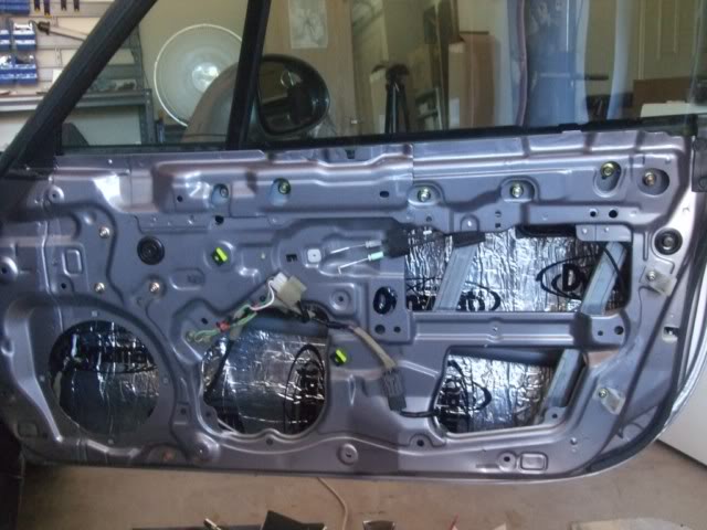
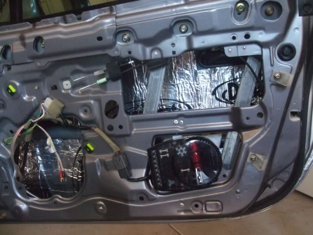
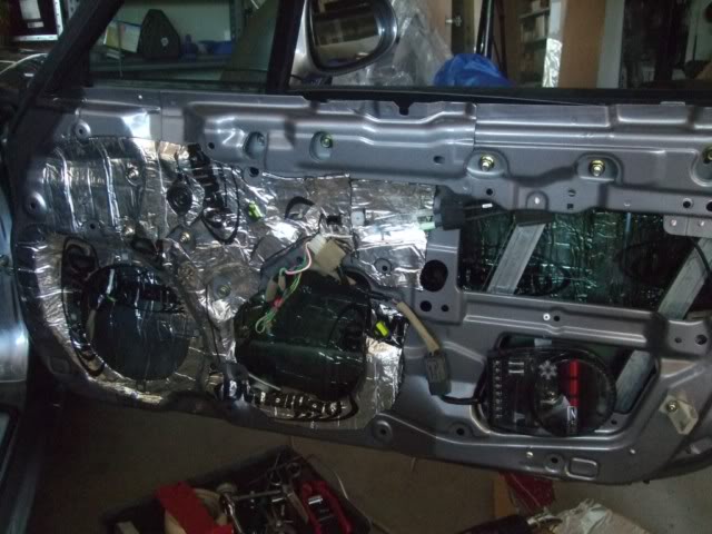
I've been getting a lot of rattling in my driver-side door which really bugged me on a recent QLD MX5 Car Club run so I decided to track it down once and for all, and while I was there, do some Dynamatting.

I could only find 2 large sheets of Dynamat Extreme (from Autobarn), not the Dynamat door kit I was looking for. The salesman told me it was the same stuff, just in a large sheet - the door kit contains several smaller-sized sheets.

After removing the door trim, I removed the plastic waterproof skin and started scraping of the horrible black tar from the door (some refer to it as "gorilla snot" which is quite apt since it's a BI*CH to get off and takes forever). A combination of turpentine and degreaser finally did the trick and I degreased the surfaces to be covered just to be sure.

I covered the inside of the outer door with 5 large sections cut from the 2 sheets:
Image

This was pretty easy since the surface is flat and is really only obstructed by the door's crash bar which can be seen in the lower 2nd and 3rd cutouts.
It's easiest to make paper templates and cut the Dynamat from the template. I didn't have any newspaper available and didn't want to buy one so after a bit of rmumaging around in the garage, I found that I'd actually accumulated a LOT of Xmas wrapping paper rolls since I usually buy a few rolls each year and end up with heaps left over. Xmas wrapping paper works perfectly for this :P

I started out using an "entry-level hot air gun" to heat and roll the Dynamat which didn't last too long before it decided to cut out. OK, I'll be honest, it was actually a hairdryer so I went to Bunnings and bought a real hot air gun which made the job a LOT easier. Just remember NOT to turn it up too high and be very careful when getting close to wires and plastic/rubber grommets since they will melt.

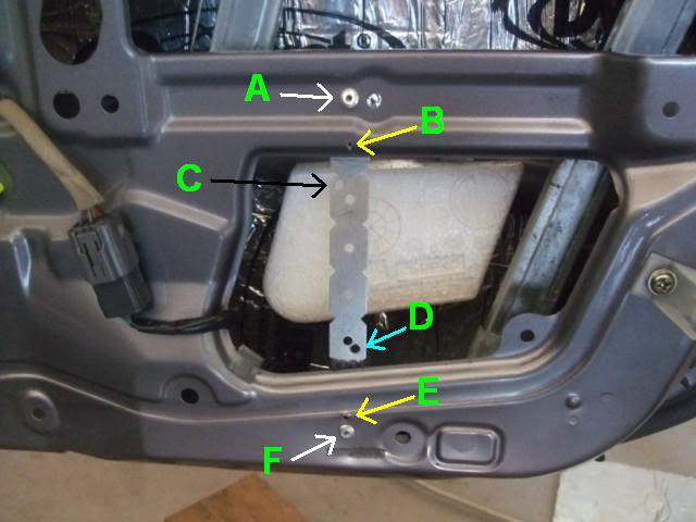
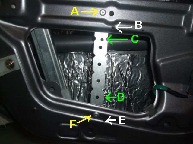
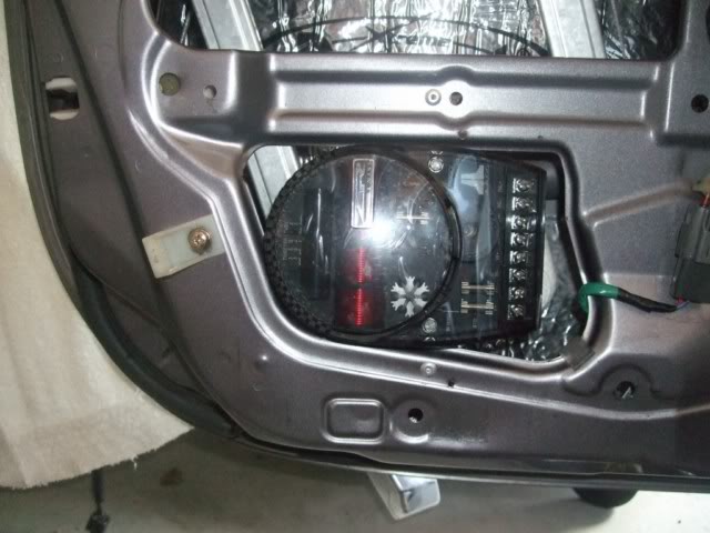
The rattling turned out to be caused by a screw which had worked loose from the speaker's crossover mounting bracket. When I first got my car, I had an alarm fitted to it and some JL Audio speakers at the same time. The slack buggers simply drilled two holes in the door frame (see B and E in the photo below of my new bracket) and used a short bracket from E to reach the bottom of the crossover unit:
Image


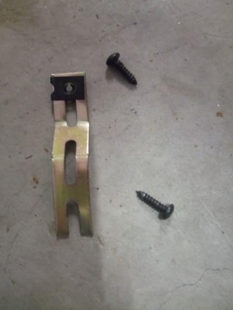
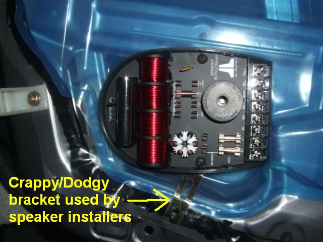
Here's the bracket they used:
Image

The top screw was used to attach to the crossover unit and the bottom to the door. It was this bottom screw which had worked loose so the crossover unit was simply swinging on the top screw - the bottom of the bracket was banging around making all the noise.

I pot-rivetted a new bracket to A & F in the 2nd photo above and drilled C & D in the bracket to mount the crossover unit. C & D needed to be at an angle to allow the crossover unit to fit securely in the cavity:

Image

The crossover unit is bolted to the bracket using 2 nylock nuts so they're not coming out in a hurry.
In hindsight, I could actually mount the crossover unit more to the right and lined up correctly because the door bracket hole to the bottom right of the crossover unit is not actually used.

The real "fun" was cladding the inner surface. I didn't simply want to clad the entire surface since I may one day want access to those door bolts and you need to ensure that all door trim slots are still clear to re-mount the door trim. The best way to do this is to use lots of small sections and cut each to measure. This takes ages :(
Image

I've got enough left to do the rest of the door this way but I lost interest about this time and I realised that my garage seat isn't really padded enough to sit down on for long periods of time. I'm not sure adding any more Dynamat will make a difference anyway.

I re-installed the original plastic water barrier and door trim and took Gina for a spin to test it out. The driver-side door is MUCH quieter and now I can hear the passenger side door rattling when I hit bumps - looks like that will be next weekend's job :( The door really feels solid now when driving.

Shutting the door now gives a satisfying THUD, as opposed to the original tinny rattling thud so that's a good thing.

As far as improving the quality of music goes, I don't really think it did much - with the top down I reckon you'd be hard pressed to pick it.

Definitely not a "Bang for Buck" audio enhancement but the car feels much more solid with Dynamat in the doors.
Don't worry about dying, worry about not living!
Garage Thread: http://www.mx5cartalk.com/forum/viewtopic.php?f=57&t=76716

User avatar
Lokiel
Forum legend
Posts: 4126
Joined: Thu May 28, 2009 2:39 pm
Vehicle: NB SE
Location: Brisbania

Re: Lokiel's "Gina" (once a 2004 Titanium SE) Recreated AGAIN

Postby Lokiel » Tue Jun 05, 2018 7:40 pm

Originally posted by Lokiel, Sun Sep 24, 2017 3:39 pm

Originally posted by Lokiel, Sat Feb 26, 2011 9:53 pm[

I installed the passenger side Dynamat today.

The following picture shows the crappy/dodgy way the crossover unit was originally mounted.
Image


After doing the driver-side door, I decided to mount the crossover more within the cutout since the recessed tab isn't actually used to mount the door trim and it makes a good brace for the rear of the crossover unit.
Image

Once again, the bracket was mounted by drilling 2 new holes (A&F) and pot rivetting the bracket to the door. I only had to drill one new hole in the bracket (C) for the crossover unit and used an existing bracket hole for the bottom mount (D). You can see the original holes used by the installers to mount the crossover unit (B&E).

Here's the crossover unit mounted using 4mm bolts+washers and nylock nuts, looks better than the driver-side (damn, that's going to bug me until I re-do it like this one):
Image


Originally posted by bootz, Sun Feb 27, 2011 1:27 pm[

uncited wrote:Here's the crossover unit mounted using 4mm bolts+washers and nylock nuts, looks better than the driver-side (damn, that's going to bug me until I re-do it like this one):


Now that may be a tad extreme :lol: . Really enjoy your projects.


Originally posted by Lokiel, Sun Feb 27, 2011 11:44 pm[

bootz wrote::
Now that may be a tad extreme :lol: . Really enjoy your projects.


Thanks.

I like to read up on whatever job I plan on doing and appreciate reading other people's posts regarding installations, especially when they include pictures and "gotchas" - hopefully others find my contributions useful.

Manufacturers often leave out details (possibly because they think certain steps are obvious) and even simple omissions can make a job more difficult than it needs to be. Comments from "DIYers" are extremely helpful, just read the Miata.net forum regarding the installation of Boss Frog "Frog Arms" for an example of this, there's a LOT of information in there that isn't in the installation instructions.

The more DIY information available the better! There's no way I would have attempted many of these projects 10 years ago without the information that is available to us now.
Don't worry about dying, worry about not living!
Garage Thread: http://www.mx5cartalk.com/forum/viewtopic.php?f=57&t=76716

User avatar
Lokiel
Forum legend
Posts: 4126
Joined: Thu May 28, 2009 2:39 pm
Vehicle: NB SE
Location: Brisbania

Re: Lokiel's "Gina" (once a 2004 Titanium SE) Recreated AGAIN

Postby Lokiel » Tue Jun 05, 2018 7:41 pm

Originally posted by Lokiel, Sun Sep 24, 2017 3:40 pm

Originally posted by Lokiel, Sat Mar 19, 2011 7:19 pm[

I quite like the old-school window chrome toggle switch mod that some NA guys have done so I thought I'd see what it looks like in an NB.

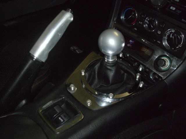
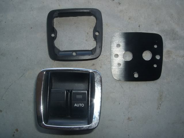
Here's what my OEM window switches look like with a chrome surround:
Image


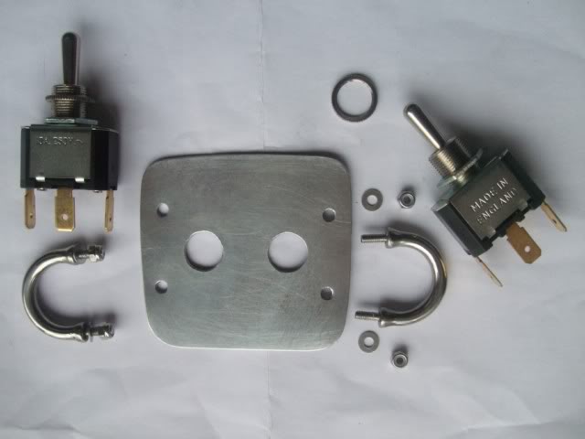
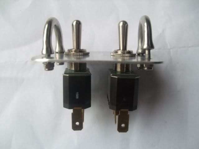
I bought a couple of DPDT momentary switches and chrome guards and made the base-plate from aluminium to fit the existing window switch slot (took forever to get right with lots of filing required):
Image


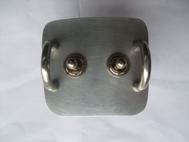
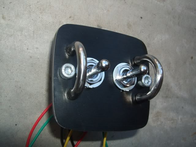
Here's what it looks like assembled:
Image

Image


Note that I haven't tightened the nylock nuts on the chrome guards since I want to paint the aluminium base plate in either chrome or black and I still need to drill holes to mount Allen bolts (matching the chrome gear lever surround) for fixing the window switch in place.

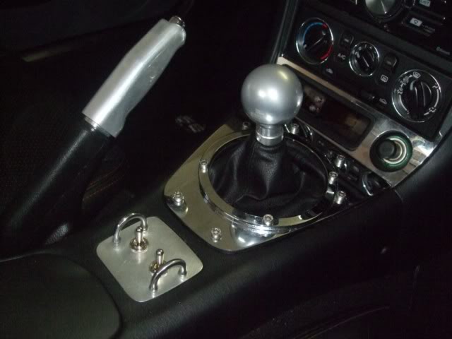
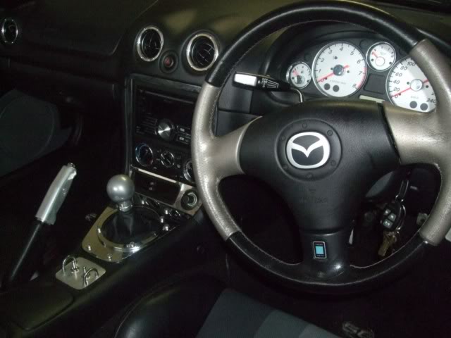
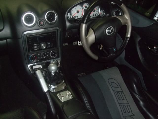
Here's what it looks like installed:
Image

Image

Image


I still need to wire it up and have another window switch that I will butcher for its socket to allow me to connect the OEM plug to.

Any opinions on the switch?
ie.
1. Paint the aluminium plate chrome (won't have to worry about scratches)
2. Paint the aluminium plate black (scratches will be a problem)
3. The OEM switch looks better
4. You've got WAY too much chrome already, you need help!


Originally posted by Crapweasel, Sat Mar 19, 2011 7:35 pm[

Interesting mod Simon - my vote would be with:

5. Get it powdercoated in silver to match the gear knob & handbrake. That way the chrome is to the front, rather than strting to creep to the back of the car.


Originally posted by MINX, Sat Mar 19, 2011 8:52 pm[

Good job Simon.
Def has potential.
The colour/surface just needs some continuity with either the chrome or brushed.
Gotta watch too many changes in finishes.

What about Wrinkle Red? :lol:


Originally posted by Lokiel, Sat Mar 19, 2011 9:18 pm[

Davex3 wrote::
It think it would look cool either brushed or brushed and anodized black or grey.

Black brushed hard anodized aluminium makes me happy in pants.
:


I like the black brushed hard anodized aluminium idea and have an old Shuttle PC case in that finish that I can butcher!


Originally posted by bootz, Sun Mar 20, 2011 1:48 am[

Lokiel wrote:
Davex3 wrote::
It think it would look cool either brushed or brushed and anodized black or grey.

Black brushed hard anodized aluminium makes me happy in pants.
:


I like the black brushed hard anodized aluminium idea and have an old Shuttle PC case in that finish that I can butcher!


Out with the dremel and give it a go!
Don't worry about dying, worry about not living!
Garage Thread: http://www.mx5cartalk.com/forum/viewtopic.php?f=57&t=76716

User avatar
Lokiel
Forum legend
Posts: 4126
Joined: Thu May 28, 2009 2:39 pm
Vehicle: NB SE
Location: Brisbania

Re: Lokiel's "Gina" (once a 2004 Titanium SE) Recreated AGAIN

Postby Lokiel » Tue Jun 05, 2018 7:41 pm

Originally posted by Lokiel, Sun Sep 24, 2017 3:41 pm

Originally posted by Lokiel, Sun Apr 10, 2011 8:26 pm[

I'm currently in the process of installing an Adaptronic e440 SE/Mazdaspeed ECU.

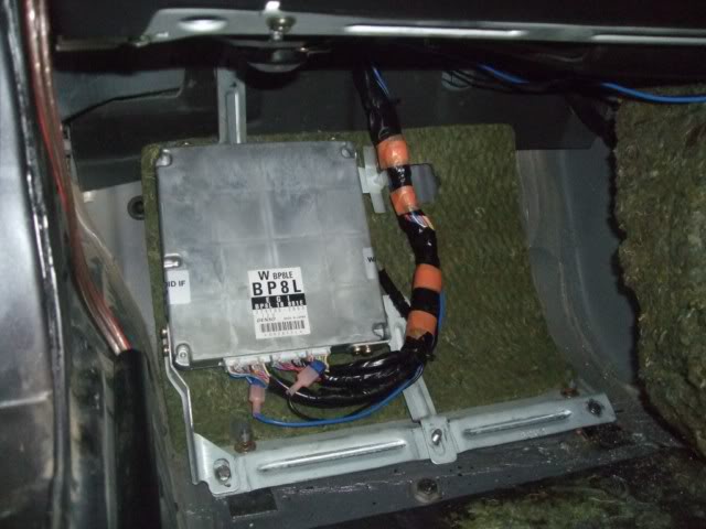
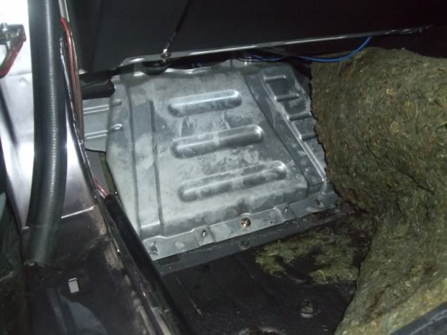
Here's where the ECU is located in RHD cars, the passenger footwell, under the carpet:
Image

Image

The top photo shows the cover plate, the lower shows the ECU under that cover plate.
Note that to remove the cover plate, you'll need to either grind off the lower two outer-most bolts or use your Dremel to cut a slice into them so that you can undo them with a screwdriver.
Those blue wires, "vampire clipped" to the ECU wires, were for my Flyin' Miata O2 Mod - these have now been removed since they are no longer required with the Adaptronic - WHOOPIE!

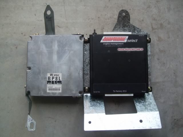
I decided to mount the e440 next to the ECU since it looks like there's plenty of room:
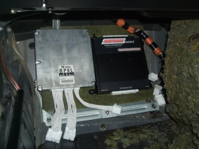
Image

The white harnesses from the OEM ECU were included with the e440 but, as you can see, unfortunately they're about 120mm too short. I spoke to Andy from Adaptronic and he's sending me some longer ones. The Americans need longer harnesses and I suspect most Aussies will too. I really didn't want to lengthen these myself, 4-8 wires is OK, but not 30 or so.

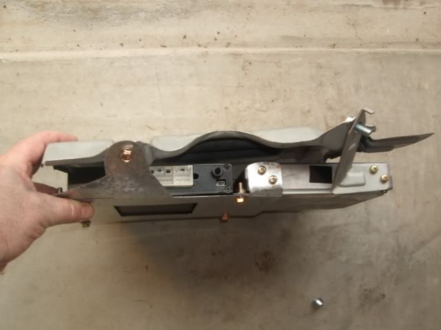
This photo shows how the OEM ECU is mounted against thecover plate:
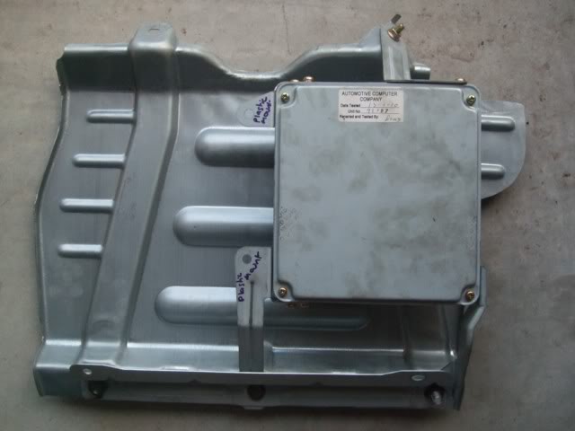
Image

The bracket on the top left is not actually mounted to the cover plate, it's merely used as a brace for the OEM harness.

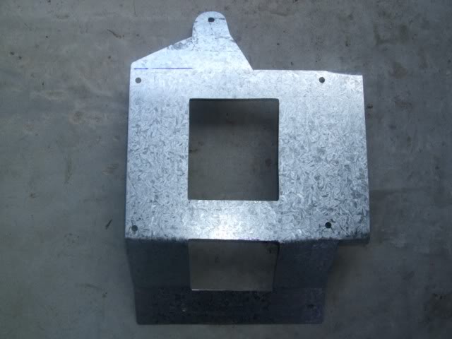
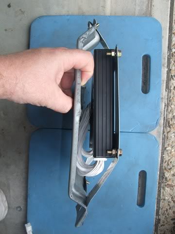
I decided to get rid of the 2 left side brackets and use the new bracket I was making to mount the OEM ECU to. Originally I planned to make the new bracket from aluminium but when I went to Bunnings, I found that the $34 sheet of aluminium I needed only cost $12 in galvanised iron so galvanised iron it was! Here's the new bracket, front and rear view:
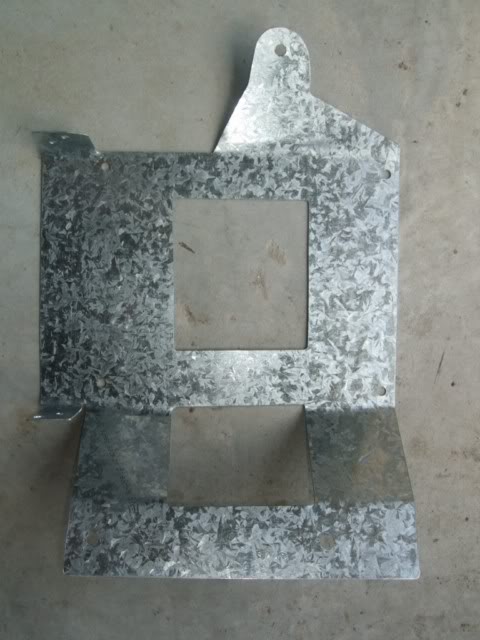
Image

Image

I may yet make those interior cutouts even larger, the bracket is strong enough to do so (my original template was made assuming I was using aluminium so I needed more rigidity). I may also "skinny-up" the top bracket too since it's strong enough in galvanised iron.

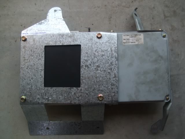
Here's the e440 mounted to the new bracket, followed by the two ECUs mounted, and a rear view:
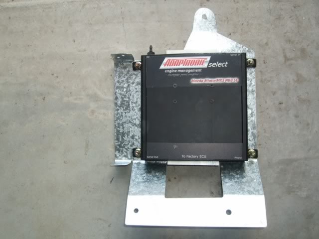
Image

Image

Image


This is what it looks like with the cover plate installed - everything's nicely tucked behind it:
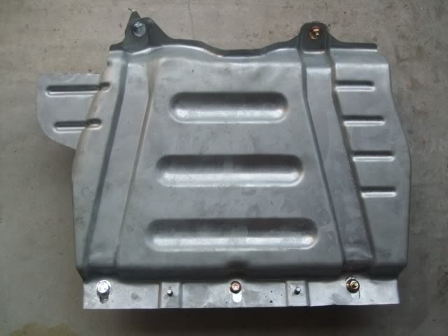
Image


Top view:
Image

Here you can see where the car's harness plugs into (white socket), the USB port (bottom right of e440) and MAP sensor port (top right of e440). The car's harness will need to be plugged in while the cover plate is off but there is room for it.

Bottom view:
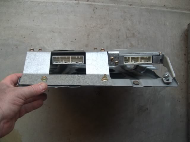
Image

The new harnesses will connect the 2 ECUs.

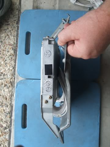
OEM ECU side view:
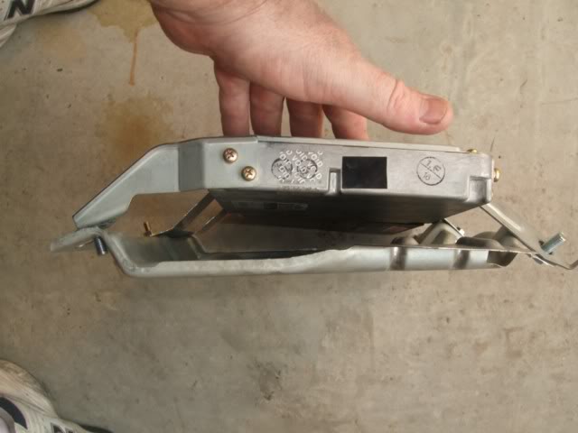
Image

This shows the OEM brackets for the OEM ECU.

e440 ECU side view:
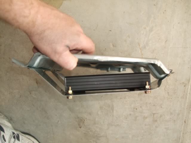
Image


Originally posted by bootz, Wed Apr 13, 2011 12:11 pm[

Very neat.


Originally posted by Mr Morlock, Sat Apr 16, 2011 7:05 pm[

Interesting- gal sheet for a pressed metal component- does it fail on the edges ( ie corrosion) ? Alu, ss , or metal later plated ( not practical for diy) might stand up longer - but agree prob academic. In the car industry everything is checked for salt spray resistance. Looks a neat job.


Originally posted by bootz, Sat Apr 16, 2011 11:15 pm[

Perhaps when you have assessed the changes you can post the effectiveness of the new ECU. I am also interested as to the process that initiated which is quite an expensive mod. Enjoying your thread :D


Originally posted by Lokiel, Sun Apr 17, 2011 8:28 pm[

Mr. Morlock: I must admit I hadn't considered bracket corrosion to be an issue since my passenger side footwell is dry - will keep an occasional eye on that though.

The longer ECU harnesses arrived this week:
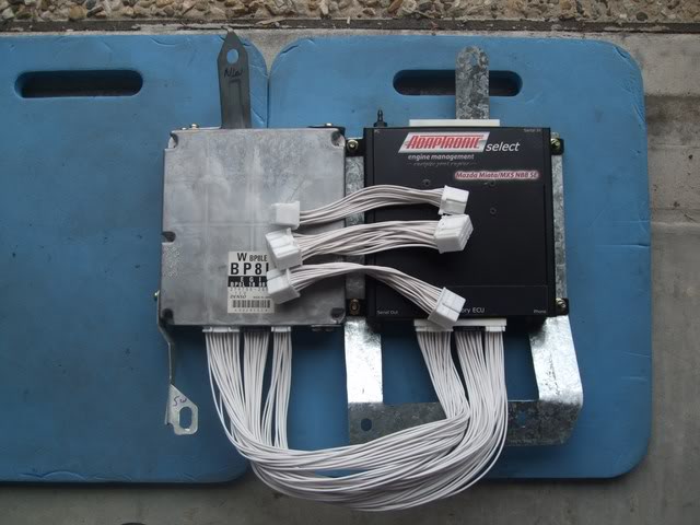
Image

These are 3 times longer than the original ones. I also lightened the new bracket by making the 2 inner "windows" larger and the top brace thinner. I also made the two bottom holes "longer" to allow it to be wiggled around a bit when mounting it.

Here's what they look like from a side view with the cover plate mounted on top:
Image

Image

As you can see, there's plenty of room to tuck the extra cable length.

Rear view with the cover plate mounted:
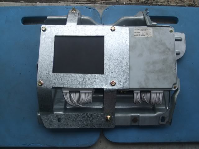
Image

When I mounted this in the footwell, I found that the bottom of the bracket was touching the bottom of the floor so I cut off 10mm from the bottom of it - I didn't want it to scratch through the footwell paint or screech when driving (metal on metal).

After that minor mod, I mounted it in the footwell. Here's what it looks like fitted, minus the cover plate:
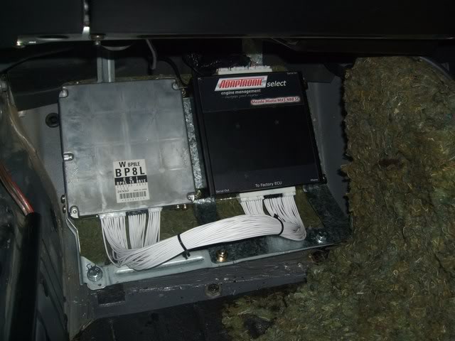
Image

It's pretty awkward getting it in there now since it's so wide. First you need to attach the OEM harness to the e440 ECU, along with the boost hose to the internal MAP sensor and connect the USB cable, otherwise you'll never be able to attach them (unless you're triple-jointed). I zip-tied the USB cable to the MAP sensor's rubber hose which should ensure that it doesn't fall out as easy.

Unfortunately my car has been sitting in the garage too long and the battery is now flat so I couldn't do any tuning today :(
Don't worry about dying, worry about not living!
Garage Thread: http://www.mx5cartalk.com/forum/viewtopic.php?f=57&t=76716

User avatar
Lokiel
Forum legend
Posts: 4126
Joined: Thu May 28, 2009 2:39 pm
Vehicle: NB SE
Location: Brisbania

Re: Lokiel's "Gina" (once a 2004 Titanium SE) Recreated AGAIN

Postby Lokiel » Tue Jun 05, 2018 7:42 pm
Originally posted by Lokiel, Sun Sep 24, 2017 3:42 pm

Originally posted by Lokiel, Sun Apr 17, 2011 8:52 pm[

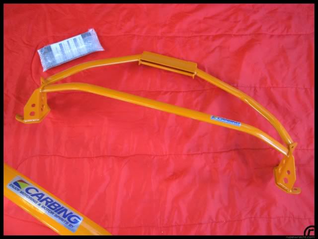
Been busy the last couple of weekends installing a Carbing 3-point front strut brace from Rupewrecht.

The brace came in the amazingly-awful "Taxi-orange" finish:
Image


I liked the brace but hated the colour (which is probably why Rupewrecht has had it in stock for so long).

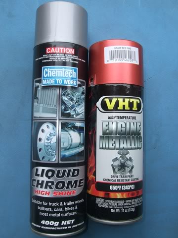
I couldn't decide between painting it chrome or metallic red so I figured I'd try both:
Image


First I sanded back the brace to its undercoat and got covered in orange dust, I looked like I'd "O'Ded" on Twisties; just as well I did it in the back yard. This took ages.

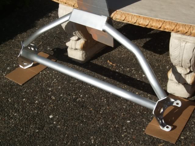
I didn't know what to expect from the chrome paint since I'd never used it before - it's more like silver paint but it does look good:
Image


Fitted to the car I wasn't so impressed since it looked too dominating and I thought red would look better:
Image

Image


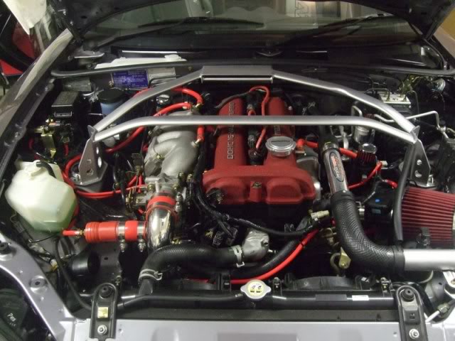
This weekend I resprayed it in VHT's Red Fire engine metallic. It wasn't as deep red as I would have liked (I had to special order it so bought it sight unseen, except for internet pictures) but it does look good so I'm happy with it.
Image

Image

Image


Rear firewall brace:
Image


With this 3-pt front strut brace, Frog Arms, Frame Rails and a Twin Hoop Roll Bar, I reckon I've got the chassis bracing covered - just as well I'm upgrading to the Adaptronic e440 ECU to compensate for the extra weight.


Originally posted by bootz, Tue Apr 19, 2011 12:03 am[

I thought the silver looked cool. 8)
Don't worry about dying, worry about not living!
Garage Thread: http://www.mx5cartalk.com/forum/viewtopic.php?f=57&t=76716

User avatar
Lokiel
Forum legend
Posts: 4126
Joined: Thu May 28, 2009 2:39 pm
Vehicle: NB SE
Location: Brisbania

Re: Lokiel's "Gina" (once a 2004 Titanium SE) Recreated AGAIN

Postby Lokiel » Tue Jun 05, 2018 7:42 pm
Originally posted by Lokiel, Sun Sep 24, 2017 3:42 pm

Originally posted by Lokiel, Sat Apr 23, 2011 9:28 pm[

bootz: Unfortunately a few others agree with you on the brace colour :( I'm not going to change back though!

Since I'm still waiting to get my Adaptronic e440 professionally tuned, the week prior to Easter was not a good time to try getting this done, I decided to finish off my retro power window switch mod using a black brushed aluminium plate as suggested by Davex3.

A few weeks ago, I got a non-functional power window switch from MX5 Plus in preparation for this mod, just in case it didn't turn out well. The problem with it turned out to be a common one, the plastic "claws" (2 per switch) that slide the encased circuit board switches up and down had snapped off so the external switches weren't sliding the circuit board switches up and down. The circuit board switches did move my windows up and down - didn't really matter, I wasn't using it anyway.

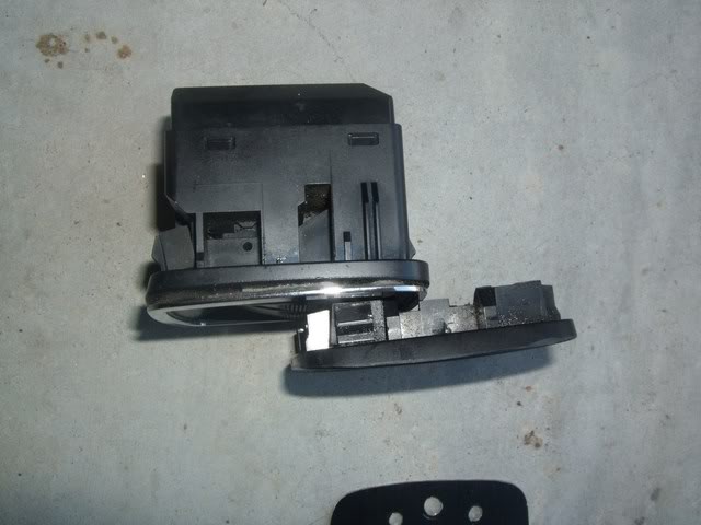
What I wanted from this power switch was its socket, so that I could plug the car's power window harness directly into it, and its top section so that I could mount the new face plate to it and secure it into position. I cut the switch down to about 10mm deep since this left the plastic locking pins on the unit. Here's the OEM version, top, and cut-down version, bottom:
Image


I Dremelled flat the two ridges that run parallel to the switches so that the new plate could sit flush, drilled 3 holes to bolt the plate to it (the position of the plastic locking pins and the amount of plastic left dictated the position of these 3 mounting holes), and Dremelled out the excess plastic to allow space for the 4 guard bolts:
Image

Note: The bottom mount hole wasn't centred and wasn't really necessary so I re-made another one without that extra mount hole.

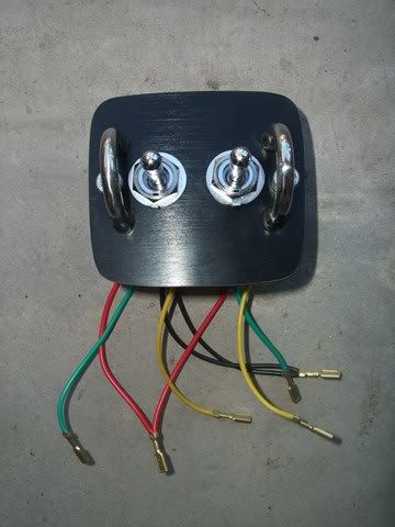
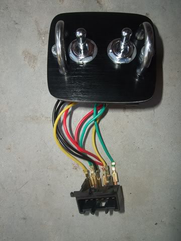
Here's a close-up of the new assembled unit:
Image


Figuring out the wiring was tricky, nothing on the web matched my OEM harness, possibly because we're RHD and everything I found was LHD.
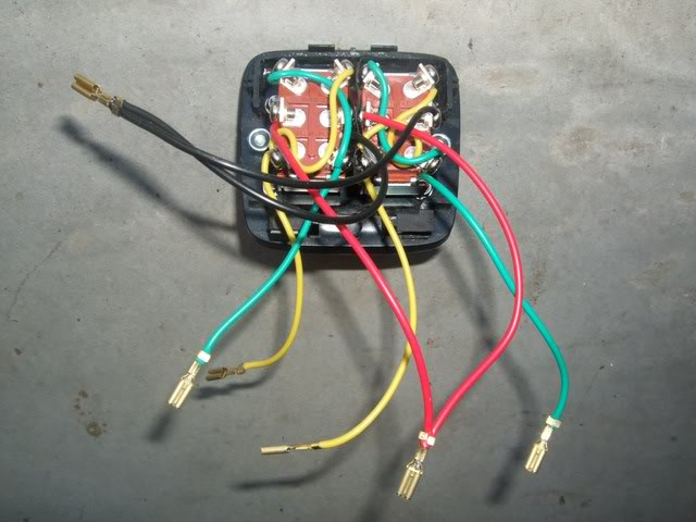
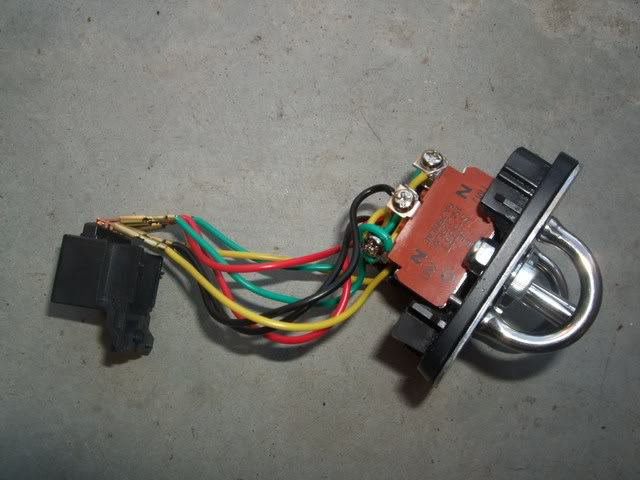
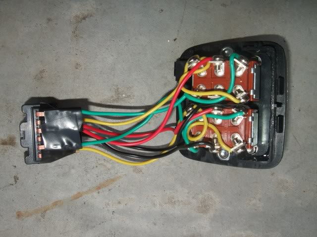
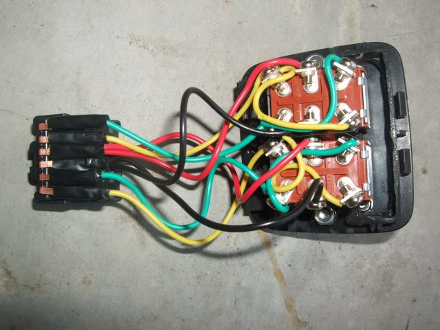
Here's how I wired it, OEM harness on left, my power window switch's socket on the right:

W/R -> Ydriver
G/R -> Gdriver
B -> B (Gnd)
R -> R (+12V)
R/G -> Ypassenger
R/B -> Gpassenger

Here's how I wired the two DPDT Toggle switch pins to my power window switch's socket::

(G)1 4(Y)
(R)2 5(B)
(Y)3 6(G)

Note:
Pins 1 and 6 are connected by (G) wire
Pins 3 and 4 are connected by (Y) wire
Pin 2 connected to (R), 12V
Pin 5 connected to (B), Gnd

Here's the bottom and top views of this:
Image

Image

Image


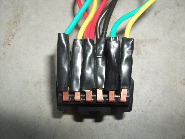
I pushed every 2nd pin on the socket forward and taped them in forward and rear groups to ensure that they wouldn't short out - the adjacent toggle-switch sides also are taped to prevent them shorting each other out since they're quite close:
Image

Image

Unfortunately when I hooked everything up, fitted the unit and turned the key, there was a faint buzz, followed by a burning smell and the windows didn't move. I recognised this immediately as a blown fuse and sure enough, the 30Amp Power Window fuse under the dash had blown, that'll teach me for doing something half-arsed :(

I pulled the window switch out and found that two of the front wrapped pins were in fact touching, probably when I was jiggling the unit into place. I taped each pin separately, visited SuperCheap for a few 30Amp mini-fuses, replaced the blown one and re-fitted the switch:
Image

Image


Now both windows worked properly and there was much rejoicing.

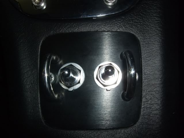
Here's a few shots of the unit installed in the car. The flash really shows up the unpainted aluminium edges of the black brushed aluminium face plate which you can't really notice otherwise - I'll have to paint those edges:
Image

Image

Image


The black brushed aluminium face plate does look good so kudos to Davex3 for that suggestion ( Wrinkle-Red was not an option :P ).
Don't worry about dying, worry about not living!
Garage Thread: http://www.mx5cartalk.com/forum/viewtopic.php?f=57&t=76716

User avatar
Lokiel
Forum legend
Posts: 4126
Joined: Thu May 28, 2009 2:39 pm
Vehicle: NB SE
Location: Brisbania

Re: Lokiel's "Gina" (once a 2004 Titanium SE) Recreated AGAIN

Postby Lokiel » Tue Jun 05, 2018 7:43 pm

Originally posted by Lokiel, Sun Sep 24, 2017 3:43 pm

Originally posted by Lokiel, Mon May 16, 2011 10:28 pm[

While waiting to get my car tuned after the Adaptronic e440 ECU install, Easter time is not a good time to get anything done quickly, my Innovate LC1 and G2 gauge turned up so I decided to install them prior to the tune.

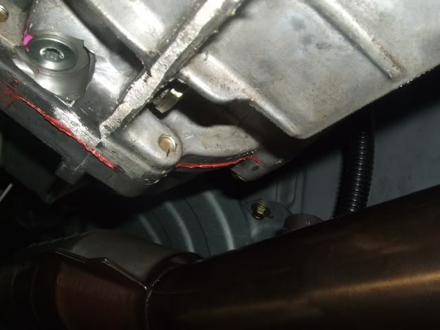
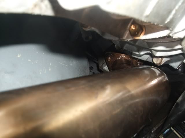
The Flyin' Miata downpipe has an O2 bung on top, just prior to the CAT so I needed to remove it to access the bung:
Image


Unfortunately I couldn't remove the top left nut at the top of the downpipe:
Image

There are 3 nuts that need to be removed, I could get to 2 of them but not reach this 3rd nut. I tried hooking up all my socket extenders, but by the time they reached the nut, there was too much flex to remove it (after this job I went and bought a couple of long extenders).

The O2 bung has a 10mm Allen key plug. With the aid of a long socket connected to the Allen key, lots of penetration oil, swearing, skinned knuckles and small turns, I was slowly able to undo the plug with the downpipe still mounted to the car. I don't recommend this to anyone, it takes forever, there's not much room in the transmission tunnel to turn the Allen key and it was all done with finger strength only!

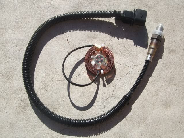
I added some split loom to the sensor cable just for some added protection:
Image

I was going to use the copper fan's heatsink in the centre of the photo since Innovate recommend a 100x100mm copper heatsink between the bung and sensor but decided against it, getting the sensor screwed into the O2 bung was going to be hard enough anyway.

The Innovate control unit was mounted to the PPF using zip ties and the wires, clad in spiral wrap, passed into the passenger footwell via the shift boot:
Image


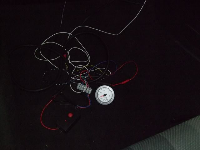
Since I wanted to mount the G2 AFR gauge in the A-Pillar, I temporarily hooked everything up in the passenger's footwell using a couple of electrical "candy bars":
Image


The LC1 sensor was calibrated, and this is how I drove it to the tuner (GT Auto Garage) and back.
Don't worry about dying, worry about not living!
Garage Thread: http://www.mx5cartalk.com/forum/viewtopic.php?f=57&t=76716

User avatar
Lokiel
Forum legend
Posts: 4126
Joined: Thu May 28, 2009 2:39 pm
Vehicle: NB SE
Location: Brisbania

Re: Lokiel's "Gina" (once a 2004 Titanium SE) Recreated AGAIN

Postby Lokiel » Tue Jun 05, 2018 7:43 pm

Originally posted by Lokiel, Sun Sep 24, 2017 3:43 pm

Originally posted by Lokiel, Mon May 16, 2011 11:27 pm[

I've wanted to install a boost gauge in my car's "dummy" oil pressure sensor ever since reading this article: http://www.mazda-speed.com/forum2/index.php/topic,13678.0.html (plus I hate my Autometer boost gauge, it lights up around the rim rather than shining through the gauge like the rest of my gauges).

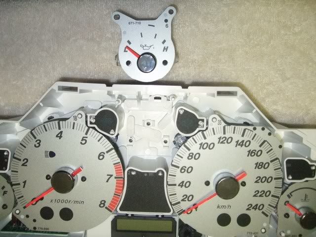
"Dummy" Oil pressure gauge removed:
Image


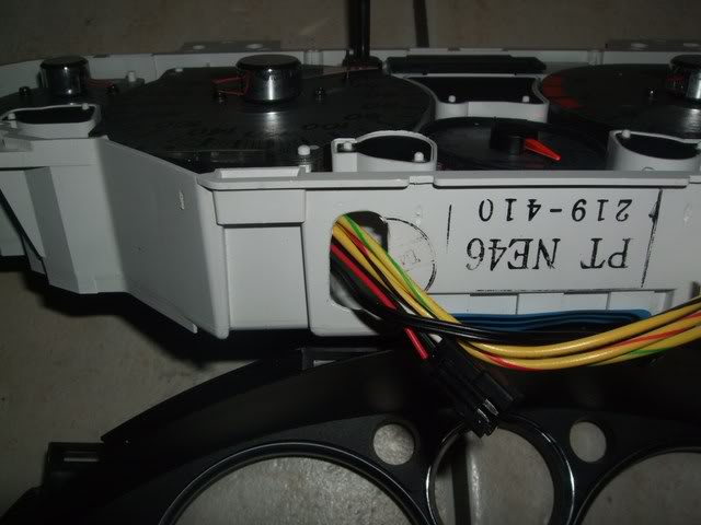
I've bought and tried several mechanical boost gauges but they're all too deep and require the rear of the cluster to be cut to provide an exit hole for the pressure barb - this would damage the rear printed circuit board so that's not an option.

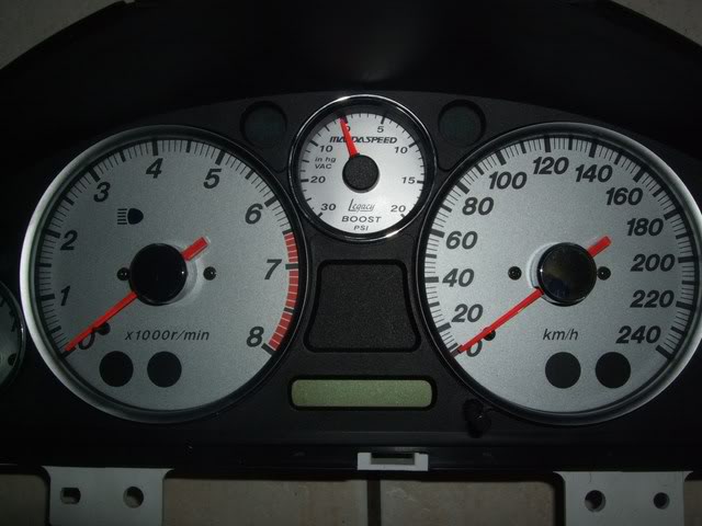
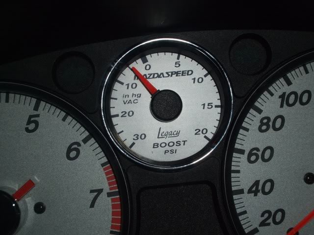
I finally decided to go all out and buy the electrical SpeedHut Legacy boost gauge while our dollar is so good. This gauge is much shallower than other gauges, has no pressure barb on it and you can customise the colour, font and dial text you want to match your other gauges. I opted for the text "MAZDASPEED" and they actually used the official MAZDASPEED font despite the fact that it wasn't actually an option - kudos for that!

Here's a SAAS mechanical gauge vs the SpeedHut gauge to illustrate the difference in depth:
Image


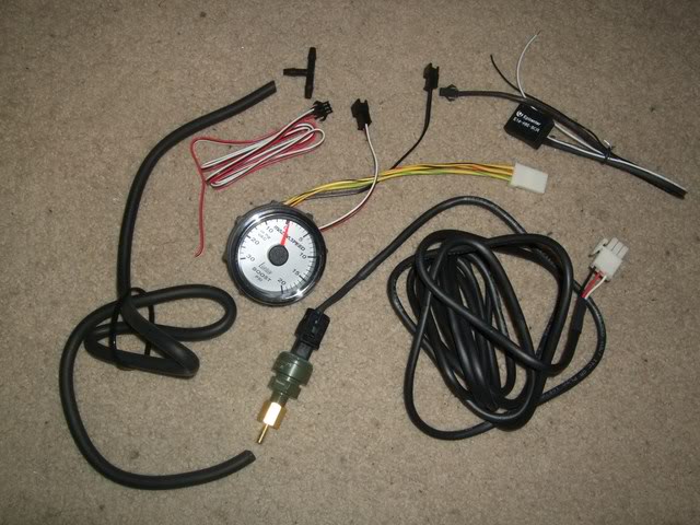
Here's the package contents - quite a bit more complicated than all the other mechanical boost gauges I have:
Image

The boost sensor cable, bottom right, must have been intended for a truck since it's about 20 times too long - I cut it down to 400mm.

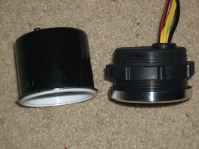
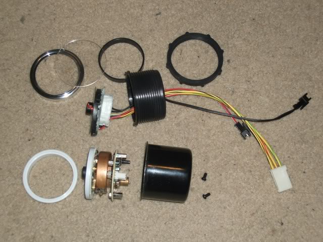
Unlike many gauges which need to be butchered to pull apart, the SpeedHut gauge comes apart by unscrewing its components:
Image


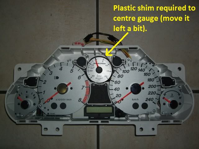
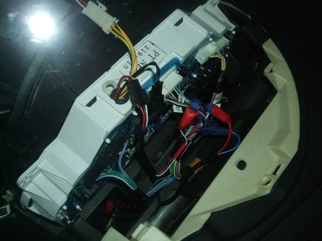
The thread on the SpeedHut's plastic housing needs a bit of filing-down in 4 places to allow it to be wedged into place. As '95MSM found, I needed to shift the gauge slightly to the left to centre it so used a plastic strip offcut. I drilled a couple of holes in the rear of the SpeedHut plastic housing and secured it to the rear of the cluster via two of the original screw holes using a zip tie.
Image

Image

Image


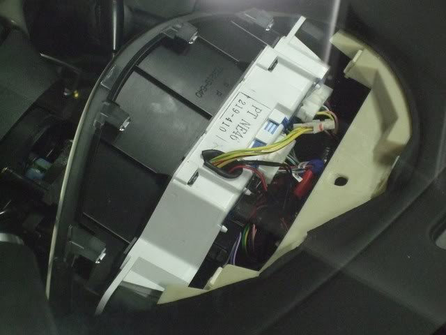
I had to cut a hole in the top of the cluster to exit the gauge's wiring:
Image


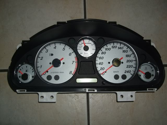
Here's the cluster all wired up, and screwed in:
Image

Image

I used vampire clips on the console harnesses to access the IGN, GND and lights +12V for the gauge (the lights +12V is needed for the gauge Needle - the instrument lights were tapped from the dimmer switch).

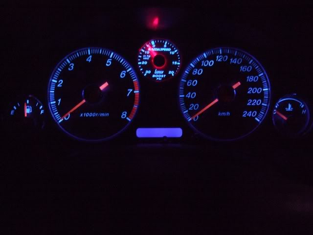
Here's what it looks like at night:
Image

The SpeedHut gauge is a little brighter than the other gauges since it has its own dedicated lighting but it's not too noticeable.

Unfortunately the gauge does not read zero initially, it's about 4 notches below, other than that it's fully functional:
Image

Image

I've sent SpeedHut a query on this since there's no obvious way of recalibrating it like the SpeedHut Revolution gauges.


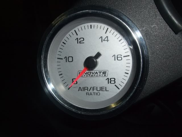
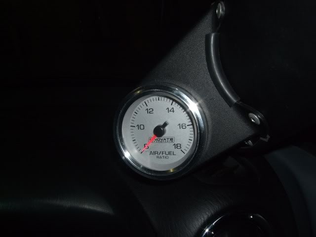
Now that I no longer need the Autometer boost gauge, I swapped the Innovate G2 AFR gauge into the A-Pillar pod:
Image

Image


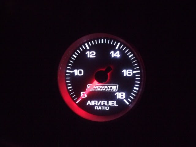
This gauge matches the silver face colour of my other gauges which goes black at night and shines with white lighting:
Image

I pulled the gauge apart to see if it was simple a matter of swapping an LED to change the backlight colour to blue but that's not the case :(
Eventually I may replace it with a matching SpeedHut gauge.
Unfortunately this gauge cannot be dimmed since its GND must be connected to the Innovate LC1's GND, it doesn't provide separate lighting wiring like most gauges
Since I had to butcher the gauge to get it apart, I was able to re-use the chrome ring from the SpeedHut gauge on the G2 gauge - initially it was a crappy metallic grey.

This took more effort than I figured it would, mostly due to figuring out the wiring and how to install it cleanly, but it's definitely worth it, I now have a boost gauge where Mazda should have put it in the first place!


Originally posted by PaulF, Tue May 17, 2011 12:32 am[

Looks great Lokiel, nice work!


Originally posted by bootz, Tue May 17, 2011 1:29 am[

I love the scrapping of the 'stupid' OP gauge, could anything be more useless. At the very least Mazda could have made it a voltmeter - would have made sense :?

uncited wrote:I pulled the gauge apart to see if it was simple a matter of swapping an LED to change the backlight colour to blue but that's not the case :(
Eventually I may replace it with a matching SpeedHut gauge.
Unfortunately this gauge cannot be dimmed since its GND must be connected to the Innovate LC1's GND, it doesn't provide separate lighting wiring like most gauges


I was wondering if you could get some hobby 'glass' paint for the bulb colour. It would also dim the bulb, maybe worth a try.


Originally posted by Lokiel, Tue May 17, 2011 1:28 pm[

bootz wrote:I love the scrapping of the 'stupid' OP gauge, could anything be more useless. At the very least Mazda could have made it a voltmeter - would have made sense :?
:
I was wondering if you could get some hobby 'glass' paint for the bulb colour. It would also dim the bulb, maybe worth a try.


The gauge uses an electro-luminescent panel so that's not an option unfortunately - I've just ordered the SpeedHut Gauge in the same colour scheme as the boost gauge because I know the non-dimmable white lighting will really bug me. I'll be able to piggyback the lighting for the gauges together too which will make wiring a little cleaner.
Don't worry about dying, worry about not living!
Garage Thread: http://www.mx5cartalk.com/forum/viewtopic.php?f=57&t=76716


Return to “MX5 Garage Chat”

Who is online

Users browsing this forum: No registered users and 27 guests