Colourful Facts about TVDs Torsional Vibration Dampers.
Solutions for Engines Seconds from Disaster !
Performance pulleys/harmonic balancers like these are claimed to protect performance engines from torsional vibration damage.


The Problem in a Nutshell
If you can relate to fun, imagine discovering a new domain of nonlinear frequencies exciting crankshaft torsional resonance irrespective of engine speed !
Not only that imagine being able to relate how Performance TVD Solutions work and then sounding super awesome on the question of having a real Problem, a Weak Link or a Loose Screw !
The Problem can be accounted for in 2 ways. In Part A, the paper takes a stirring account of the situation while in Part B it takes a more sobering account of the situation.
Either way for a forged BP crank, there is no Problem however there is a weak link in the chain and it is the BP oil pump mated to the extended nose of the crank !


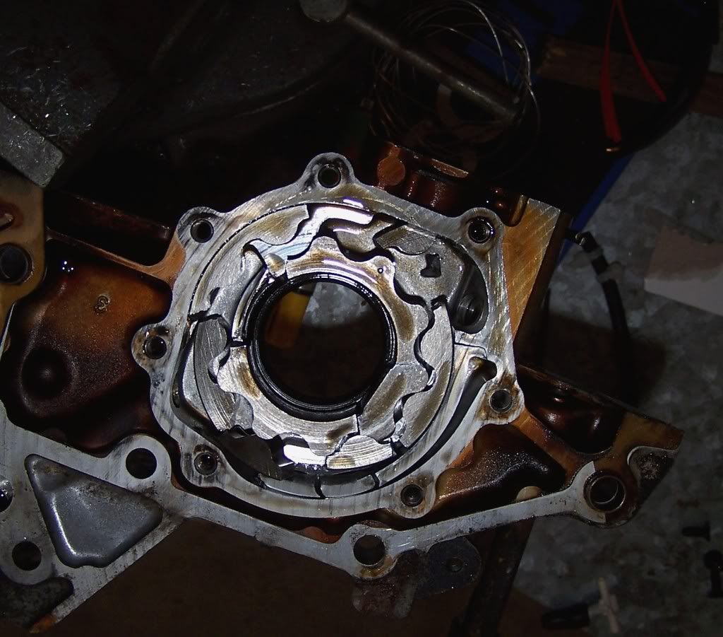
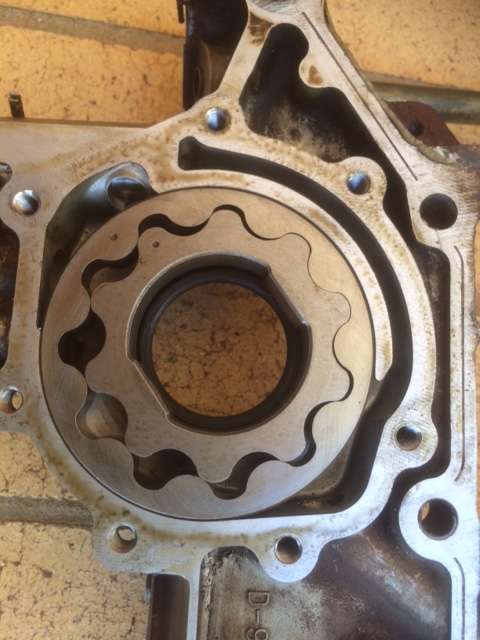
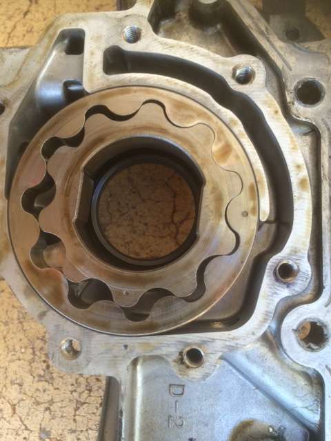
Above image shows the bigger Gerotor needed to take the MX5 big nose crank appears inherently weaker than Gerotor to suit early 323 long nose cranks.
MX5 BP oil pumps are possibly inherently weaker, offset to an extent by slighter longer thrust faces.

See the absence of constant reaction from the outer rotor and large range of pressure reaction between inlet and outlet ports.
The changing reaction felt by the thin section inner rotor at every turn under the prying force itself would repeatedly want to flex the rotor outward and crack it open.
Specifically these pumps have two issues:
- lack of robustness of the male/female crank coupling due to the too thin section inner rotor for the forces generated.
- lack of effectiveness of the relief valve under pressure ripple or pulsed flow.
The cheap nasty big nose coupling is not a robust design and so unlikely to survive high torque impact under racing/extreme performance conditions.
Its low torque/high thrust nasty design with enough clearance possibly to imagine amplifying the thrust on the flimsy pump rotors to damaging levels via a process of nonlinear vibro-impact.
Why imagine vibro-impact, abeit quiet ones? Because this crank to pump coupling clearance researched in some non BP cases on the web is super ridiculously sloppy !

Interestingly BP crank/rotor clearances in samples actually measured by the author at 0.03 mm were 15 times tighter than this ridiculously sloppy non BP example.
Now imagine a crank nose repeatedly and mercilessly slapping the insides of a sloppy rotor when the resistance is not in harmony with crank impact.
Now imagine pulses in pump flow from turning impact on the Gerotors generating variable flow in the oil pump cavity and likely instability in the control of the relief valve spool.
Now imagine inherent phase delay of the variable relief flow causing chatter from pressure ripples within the pump itself amplified by vibro-impact.
Now also imagine pump cavity pressure ripples at 2280, 4560, 6840 and 9120 rpm exciting the fundamental twisting mode of the crank (380 Hz) not helping matters.
So the Problem could be as simple as that. A weak link to be managed directly by attention to clearances and intended use or maybe using Ideas presented in this paper.
No need necessarily for tricky TVD technology to help fight that scary steel shattering, vibration boogey man, "Mr Resonance" we hear stories about.
Stirring up Thoughts - Part A Items 1.0 to 6.0
1.0 Listen to Tails of The Silent Killer !
Broken Cranks !
Clutches and Flywheel Bolts coming Loose !
Cracked Blocks !
Cracked Mains !
Broken Oil Pumps !
Hammered Bearings !
According to this Aussie analysis 4 cylinder engines are the most in need of such Solutions !
According to this Yankee analysis all engines face dire Consequence from solid lightweight aluminium pulleys !
Also beware that a geek risk to a normal mind exists if one tries to fathom the best 4 Cylinder Solution.
2.0 Don't Worry BP Cranks !
Consequence of crank failure can be a big worry while calming words re the Probability of failure is merely a quaint idea from some old crank.

To deal with our fear of killer vibrations we must start with the very basics at the very beginning. A very good place to start is where the OEM engineers left us....with no nonsense.
Unlike V8 and 6 cylinder engines, 4 cylinder engines are full of vibrations, made good by good design for those mighty good revs we yearn for.
OEM engineers ensure that critical components meant to safeguard reliability of their products are satisfactorily maintained.
So if the rubber properties in a TVD were there to protect the engine from torsional vibrations then would not there be a TVD service documented somewhere ?
Like the steel rubber composite timing belt, the OEM could easily have required the steel rubber composite pulley to also be renewed at probably the same time (100 km Service).
So maybe the BPs OEM TVD is not so critical then ? Maybe it is just there for NVH rather than as critical protection.
3.0 Seek 2nd Opinion !
Once Harmonic Balancers were seen only on low rev V8's and sixes, not on high revving big bore short stroke English prototypes of today's "Fast Four".
FFs were made cheap and reliable in Japanese Toyota 4AGE 16V & 20V engines prototyped in Twin Cam/BDA "Roaring Fordies" (Cortina in the 60's and Escort in the 70's).
Those English prototype 4AGE engines would rev to 6000+ rpm all day despite cheap cast iron cranks with solid pulleys.
Confused, maybe when the subject turns to experience with 4 cylinder engines, publicly accused metal shattering killer vibrations may be innocent !
Lets ask our enthusiastic research assistant to explain to our tiny brains how a few cylinders firing and effectively hammering away on the pistons could produce such killer crank vibration.
This nonlinear excitation feeding energy into resonant peaks somewhat independent of revs, imagined from hammer blows of an unrestrained crank all seems a lot of confused nonsense.
Fantastic imagination led us to make the Right Connections to JOIN THE DOTS to prove nonlinear analysis (needed for properly concluded research) is not rocket science after all.

Mercilessly connecting the dots turns plausible nonsense that people readily accept into perfect sense that people fully understand.
Funnily enough that makes perfect sense because the material published by some aftermarket pulley suppliers is itself not rocket science either.
This is because their nonsense is proposing a complete crankshaft vibration OSFA Solution to crankshafts without the Problems they claim to fix. (OSFA = One Size Fits All)
4.0 Establish Context for Such Nonsense
Japanese, British and European tuners are overwhelmed by introduced TVDs because American tuners make awesome examples and brag nonsense about them.
Their BIG engines didn't get a workout from revs because OEM engineers substituted "cheap fuel" for "x" in their equations to get this inescapable conclusion still embraced by the diehards.
So Yank Tanks evolved using cheap cubic inches instead of cheap revs in cheap inefficient BIG engines that the OEM engineers were free to inflict upon fellow consumers.
The result was an invasion of BIG engines across the country preconditioned for nasty Consequences from those consumers free to demand their God given Rights to more revs.
This demand then spawned the Performance TVD industry happy to claim their Big engine cure as a Small engine cure as though it was a snake oil treatment for lower parts of the engine.
5.0 Specific Evidence to Establish Context
Simply join the dots to 20 years ago when disciplined Japanese 4 cylinder cheap rev technology for the aging V8 was granted in the Toyota UZ complete with cheap rev friendly DNA.
Cheap rev friendly DNA sequenced 4 valves per cylinder, quad cams, a forged steel bottom end with deep skirt and 6 bolt mains establishing a V8 standard borne out of expensive fuel.
The old DNA sequence of 2 valves per cylinder, single cam, push rods, cast iron bottom end with no skirt and unbraced 2 bolt mains could no longer sustain the survival of the V8 species.
Now compare the extra vibration at high revs in the genes of USA engines born of primitive Cubic Inch DNA.


__________Traditional Jap V8________________________________Traditional Yank V8____________________
So V8 crank resonance found at racing revs, a weak cast iron crank and flexible anchoring to the block are preconditions for failure.
Add a hot rod/drag culture, and America got what is obvious, flying flywheel and harmonic balancer parts into the flesh of innocent bystanders.
Inevitably, out of the chaos and mayhem had to come the fix....1.2 of the Competition Rulebook which guarded flywheels and banned OEM harmonic balancers.
But the Consequence of that rule were cranks breaking from greater exposure to fundamental mode resonance at racing revs.
Inevitably, that created a demand for high rpm spec harmonic balancers in motorsport to an agreed SFI SPECIFICATION 18.1.
So inevitably born in the USA, were motorsport mandated pulleys...a Solution now in search of a Problem elsewhere.
But that Problem can be hard to find elsewhere when elsewhere, engines are born of rev friendly DNA from decades of survival on expensive fuel.
6.0 Cubic Inch Vs Rev Friendly - Compare the Flywheel DNA
The dire V8 Consequence at racing speeds is easily imagined by el cheapo external counterweighting of weak V8 cranks by heavily imbalanced cubic inch DNA flywheel pictured.
Whilst not a torsional vibration, the bolt load still contributes Consequence likely to befall the V8 crank/flywheel at high revs.

A balanced BP flywheel is relatively better held on by 6 x M12 bolts on a 65mm PCD than this grossly out of balance V8 flywheel using 6 x 7/16 (11.1 mm) bolts on a 75mm PCD.
See the comparison to a rev friendly racing V6 crank bolted joint holding a tiny flywheel and multi plate racing clutch.

Settling on Ideas - Part B Items 7.0 to 15.0
7.0 Its 100% Probable that Rigid Things Flex
To figure out our Probability of a Problem with flex just watch free of spin, one of many ways a crank might naturally want to torsionally flex creating points of high stress range or hot spots.
Instead of a boring straight, the twisty bits of a crank allow excited vibrational stress range, to have a crack at the corners.
Now imagine the crank and flywheel as a lumped mass oscillating at a lower frequency again from windup and let go of the long drive line behind the engine.
Modes might even exist in torsional vibration traces which are actually driveline mode response measured in part as "roll oscillation" of the crank.
When a BP engine designed for a FWD 323 is fitted to an RWD MX5, the lower frequency torsional response felt at the crank pulley could well be more significant.
The design of the flywheel can have a significant effect. For example, Dual Mass Flywheels can also disrupt any driveline resonance peaks seen at the front of the crank.
Also lighter or heavier flywheels can shift driveline resonances up or down the rev range away and raise or lower the driveline response.
8.0 Wake Up to Important Poignant Concepts and Connections !
1 - Motion is both whole (or rigid body) and vibratory motion. Under the microscope are wet noodle like vibration modes superimposed on a rigid spinning shaft.
2 - Wet noodle shapes are frequency exclusive linear modes of flexible mass rhythmically stimulated by natural linear spring/flexural motion.
Complex non linear motion seen in a Time WaveForm (TWF) can leak forced energy into concurrent wet noodle natural linear modes analysed as Fast Fourier Transforms (FFTs).
3 - Modes are resonant response motion responding or dancing to rhythmic energy input at an enormously stimulating critical rate or rhythm.
Surprisingly rather than stiffen up, metal shaft response to rhythmic stimulus is to flex and flop like a wet noodle made of super rubber strong enough to snap the heavy suspension cables of a bridge.
Now watch the computer stop the spin and exaggerate and slow the oscillation to help imagine this super rubberisation of the metal caused by giving it the right rhythmic stimulation.
4 - Damping is easily imagined as "a bit of a dampener". That is something which can dissipate all the stimulus energy if you can imagine that.
Dampers use mechanical and viscous friction to convert relatively large stimulus into a relatively small amount of heat.
Oddly "a bit of a dampener" on a fully stimulated metal shaft, actually transforms a tragic wet noodle to a glorious stiffened member.
5 - A bit of a dampener is best seen as a small expendable mass loosely attached to the main mass in which all the stimulation becomes apparent.
Once the effect of the stimulation becomes amplified in the response of this one small mass, one can grasp on how it might be successfully dampened.
From this flows the concept of a "tuned sprung mass" absorber, having just one frequency in mind and seeking out that frequency and its harmonics at every opportunity.
6 - Non linear excitation makes it easier for a tuned mass absorber on the front of a crank to find frequencies it needs to function properly.
7 - Vibration Excitation and Response can be either Natural or Forced or both.
The presence of cylinder ignition and piston sliders along the crankshaft means much of the vibration seen by the TVD is forcibly applied non linear vibration.
Cylinder firing against crank piston sliders creates a torsional time waveform totally unlike a nice smooth rotating imbalance sine wave response shown here.

Unlike smooth linear excitation, firing up 4 slider/cranks produces muffled "hits of connected hammers" each hit a sudden step impulse too quick to transform into solid spin behaviour of the crank.
Imagine each impulse having overshoot absorbed by spring windup in the crank.
The video shows how translation spring energy is released elastically in the frequency domain via a range of vibratory motions courtesy of dampened spring release.
Likewise torsional twist of the crank nose is a spectrum of non linear oscillations indistinguishable in the time domain but separate and distinguishable in the frequency domain.
Now each non linear vibration frequency can be further transformed in the time domain by Fourier Transformation into simultaneous linear vibration frequencies.
This completes the transformation of non linear energy input from the time domain into a range of linear frequencies in the frequency domain.
Most of these linear frequencies relate to twisting modes and their harmonics quite weakly, however in certain cases a few may relate strongly enough to be of concern.


As seen in these animations, the energy absorbed (area under the curve) of the higher frequency vibrations are relatively low.
This and the high velocity of such vibration means only tiny levels of damping is often enough to prevent damaging resonance build up of high order harmonic vibrations.
Imagine repeated energy steps even more complex absorbed elastically by the structure in a tiny integral of time.
Imagine then the energy transformation into a chain of frequencies many of which will fall on the many modes available, so as to form resonant peaks at any and all engine revs.
9.0 Imagine a two Rotor Shaft
From the point of view of torsional excitation the crankshaft is considered a two rotor shaft with masses at each end acting as inertial restraints.
The flywheel is a large inertia rotor at one end and the front pulley is a small inertia rotor at the other.
At each cylinder are spinning lumped masses with attached sliding lumped masses comprising big ends and balance weights attached to piston/conrods. (sliding masses not shown)
The most extreme torsional vibration is this, its lowest frequency resonant response or fundamental torsional mode:
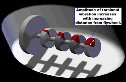
- most twist is seen at the pulley,
- much less twist in the opposite direction at the flywheel
- no twist in the crank just ahead of the flywheel.
- maximum torque plus torque impulse occurs at/near the bolted connection of the flywheel to the crank
The flywheel is connected to a driveline and the pulley is connected to belt dríven auxiliaries.
Now both the drive train and the auxiliary drives are highly flexible so do not provide nearly as much dynamic restraint involving crank twist.
High frequency vibrations involve actual crank twist restrained by flywheel inertia, such that the crank can resonate about a node point just forward of the flywheel.
The heavier the flywheel the lower the resonant frequency and the lighter the flywheel the higher the resonant frequency.
The heavier the front pulley the higher the resonant frequency and the lighter the front pulley the lower the resonant frequency.
From this one could imagine the more counterweights the crank has, the lower the twist and higher the frequency of torsional vibration at the front of the crank.
So how do you take the torsional vibration out of the crank and rev it faster ? You break the mould and rethink the 2 rotor design with a heavy flywheel at one end.
Take a look at the Honda S600 crank designed to rev to 11,000 rpm with heavy counterweight and small clutch light flywheel design.

So heavy counterweights, light flywheels and small clutches will lead to longer lasting cranks still free of 1st mode fundamentally forced vibration despite insanely high revs.
10.0 Realise Cranks ain't Cranks
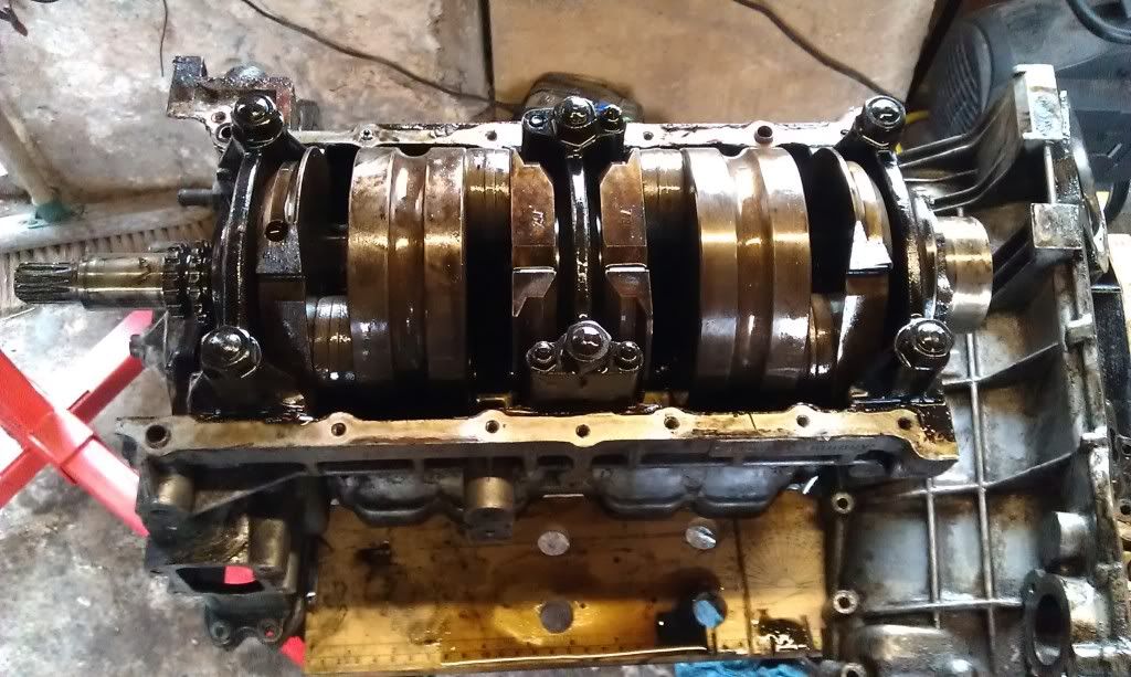
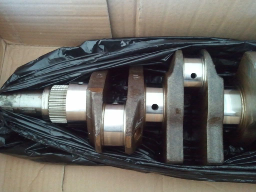
Compare BP cranks: the cast 323 big nose crank at top of image, the big nose forged 323/MX5 crank, and the forged small long nose forged 323 crank at bottom of image.

The meaty crank counterweights on the forged BP cranks are good things for crank life. They help make the forged BP crank stronger than the lightweight cast crank.
Similarly a heavy TVD by its mass inertia makes an engine smooth because it anchors the front of a crank much like a flywheel anchors the rear of a crank.
Therefore plenty of Placebo Smooooothness should be possible with a BP forged crank via a heavy TVD properly blinged up.
The resonant frequency of the fundamental mode of oscillation seems to range between 300 Hz and 450 Hz. (Where 1 Hz = 1 cycle per second)
It appears a small block V8 would resonate around 400 Hz, a 4 cylinder around 380 Hz and a 6 cylinder around 350Hz.
Now a V8 fires 4 times per rev, a 6 cylinder fires around 3 times per rev and a 4 cylinder fires 2 times per rev.
The fundamental crank resonance frequencies therefore are described as 2nd order, 3rd order and 4th order for the 4, 6 and 8 cylinder cranks respectively.
Therefore fundamental resonance for a V8 occurs around 6000 rpm, a 6 cylinder around 7000 rpm and a 4 cylinder around 11,000 rpm.
This tells us we do not have enough revs for a racing BP to fundamentally resonate like a revved up V8 Ford or racing inline 6 BMW.
So there is little risk of lowest order crank resonance occurring in an OEM 4 at racing revs, so no harm likely.
However racing an OEM V8 or 6 at such revs without a TVD or DMF is some say, to silently ring its neck until one day it is dead.
Now imagine a shorter and stiffer crank in a flat 4 and you can imagine WRX drivers at the track saying.....No worries mate !
Nevertheless due to the non linear impulses on the crank, it is likely that harmonics will raise smaller resonant peaks for this mode at lower engine speeds and chances are the BP crank is ok with that.
Imagine a small block Ford crank verses a BP Crank and you can imagine how much tougher the BP crank is.....


__________________Ford 351 V8 (5750 cc) SG Cast Iron ___________________________________________Mazda BP (1840cc) Forged Steel
__________5.8 litre V8 (351 Ford)______________Mazda BP
Cylinders___________8_______________________________4
Bore______________102_____________________________83
Capacity___________5759____________________________1840
Pot Size____________720____________________________460
Bore Spacing_______111_____________________________91
Material__________Nodular cast iron, nitrided___________Forged Steel
Mains______________5_______________________________5
Mains Diameter______69.8____________________________49.9
Rod Diameter_______58.7_____________________________44.9
Rod width__________42.9_____________________________
Crank Weight_______26.8_____________________________16.2
cc/kg_____________214______________________________113
Length C/C_________376_____________________________273
Length O/O_________487_____________________________364
V8 is 34% longer, 65% heavier, in an engine 313% larger with a 60% bigger firing impulse.
By comparison the V8 crank has 300% more torque and 60% more torque impulse but has only 23% more unit mass, and is only cast iron.
Clearly BP cranks are much more robust (built for revs and vibration).
11.0 Define the Problem - Real Damage or NVH ?
Imagine this thing, the banana bracket supporting inlet manifold (intake brace). What is its core purpose ?
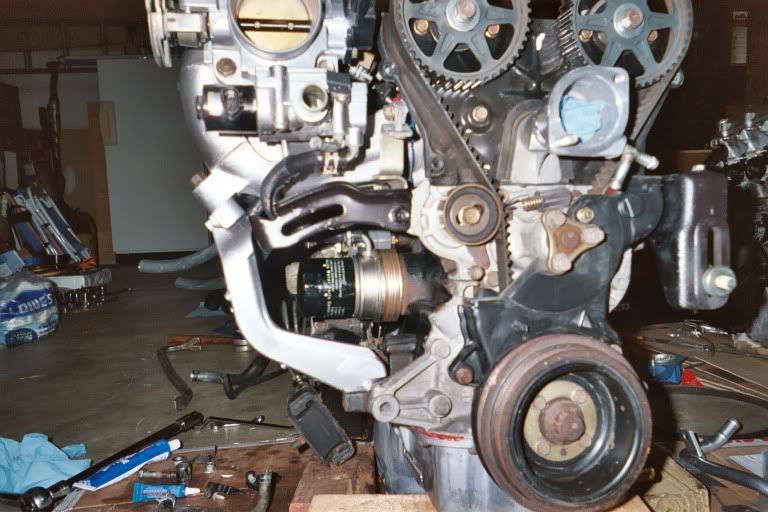
Performance TVD's also appear to lack direct cause and effect evidence pointing to its core purpose on a 4 cylinder. So are TVDs really needed for a Fast Four ?
Now imagine a crankshaft at any rpm, subject to repeated complex energy steps and shocks absorbed elastically by the structure in tiny integrals of time.
The whole body responds in the time domain (continuously changing rotation) together with the elastically connected body responding in the frequency domain (flexible mass vibrating).
Then one might imagine the series of harmonics extending into the audible range, so creating a potential noise source at the most torsionally responsive part of the crank, its nose.
In other words, a small part of the energy transforms into perfect, natural and timeless vibration at higher frequencies in the audible or buzzy NVH range.
Then the full sweep of noise emitting vibration is likely to excite thin responsive and thus noise emitting hardware (like covers) in the vicinity of the nose.
Therefore imagine an elastomeric pulley would be a useful OEM tool for blocking the noisy vibration path to the exposed and relatively light pulley and belt drive system.

Transformations will occur at the frequencies occupied by each and all crankshaft modes as well as at the harmonics those modes will sustain.
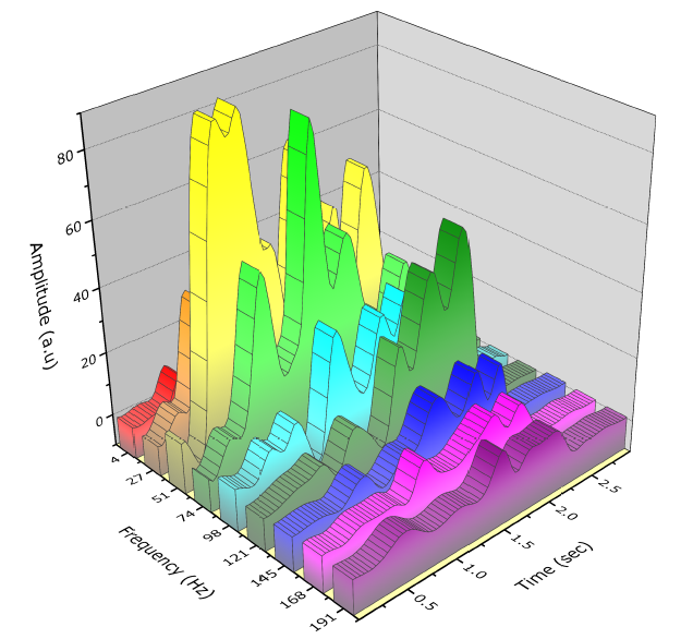
This effect may be seen as many spikes in the broad spectrum vibration traces of crankshaft torsional vibration through the rev range.
The 1st, 2nd, 3rd, 4th and 5th harmonics of four phased piston firings exciting the fundamental mode would result in say 20 relatively tiny peaks spread between 920 rpm and 5,500 rpm.
Note "the degree of twist" in the spectrum seen at the front of the crank may not be all 1st mode flexural twist (the cause of critical torsional stress), if the front of the crank is also responding to a harmonic of another twisting mode.
The same applies if the response measured is partially whole body "roll oscillation" of the crank from a driveline mode.
Vibration accumulates at resonant frequencies on top of the rpm dependent forced frequencies from impulsive cylinder firing, piston motion and mass imbalance.
However these are not 4 cylinder crankshaft fully coupled harmonic excitation because such impulses do not resonate in the rev range as is possible with V8 and in line 6 cranks.
In other words a 4 cylinder crank is unable to ever sing in concert, a Full Chorus Hallelujah "enough to bring the house down", fundamentally forced like a V8 or in line 6.
Now more small torsional spikes occur in the rev range of 4 cylinder engines. These may be lower order excitation of torsional crank modes from other sources like imbalance.
Alternatively they could be non crank modes felt from elsewhere in the drivetrain/accessory drive as a small torsional spike.
However the magnitude of such spikes is likely to be of little Consequence to such a robust structure as a BP crank.
So if all possible vibrations are small anyway, then a TVD may have no real Consequence on cumulative exposure and thus life expectancy.
As Probability sets life expectancy, it may be that for a forged BP crank that the benefit obtained from major pulley investment is to reduce vibration from "not harmful" to "even less harmful".
Having said that, the existence of a flywheel effect, "loose" mass and perhaps a touch of hysteresis damping, the case is clear for less vibration, smoother running and less NVH.
So while the claims of reduced vibration are valid, any claims of damage to a BP would be much less so.
The pulleys reduce the NVH factor and the engine will run smoother, but hard to imagine much smoother than with a TVD of similar mass.
12.0 Realise TVDs have a Split Personality
Non linear transformation into TVD frequency response is not simply energy dissipation and reduction of a large resonant peak by damping.
It can instead transform without damping into harmonic balance (saddle or cleavage) involving remnants of a pair of adjacent resonant peaks.
Depending upon the dynamic stiffness of mass configuration in a TVD, it resonates both fully "locked" (dead hard) and loosely bound "dead soft". (Refer diagram below).
A solid pulley resonates dead hard or "locked". A TVD is therefore classified in this Paper as either a :
Class 1. Multiple Mass Pulley (Pendulum Pulley) or a
Class 2. Dual Mass Viscous Dampened Pulley or a
Class 3. Tuned Sprung Mass Absorber (Optimised Damper) or a
Class 4. Dual Mass Elastomeric Pulley (Harmonic Balancer)
Note: Damping in Class 1 and Class 4 TVDs, is relatively unimportant so can likely be ignored, but damping is important in Class 2 and Class 3 TVDs.
Class 4 TVDs can be optimised to work best over frequency ranges but this is not using the significant damping function as say critically tuned Class 3 TVDs.
Class 2 Viscous Damper pulleys are easiest to imagine via connection to the rhythmic dance tuned sprung mass absorbers and tight jeans damping outlined earlier.
But unlike silicon implanted energy absorbers like viscous dampers, Class 4 elastomeric harmonic balancers do not rely on such peak reduction procedures.
Instead imagine a a pair of standout resonant peaks simply broadening and flattening out with Class 4 elastomeric TVDs typically used on OEM BP engines.

The OEM pulleys are seemingly optimised for every day NVH in an optimised band of the frequency spectrum, spreading resonant energy across remnant twin peaks.
The remnant peaks are offsets of each original resonant peak that tries to form but is brought down by the destabilising effect of its neighbouring peak trying to do the same.
Damping (eg rubber hysteresis) plays no part in bringing down the twin peaks; they bring each other down.
Imagine a non linear vibration oscillator in a region of instability between two limiting modes where the TVD harmonically balances its frequency response as per the above diagram.
So if the TVD is not optimised for the broad frequency band, the twin resonant peaks may not form evenly enough to harmonically balance the resonant energy.
In that case damping is required to reduce resonant peaks, meaning that for consistent speed engines for example, elastomeric TVDs may be more at risk of overheating.
When energy flow into resonance is high, such as when a full chorus Hallelujah or rhythmic dance matches the fundamental mode, damping (ie tight jean friction) is critical.
This suggests Class 3 TVD with "sprung masses" and "tight jeans" to reduce excitation is likely needed if the crankshaft's 1st mode occurs during racing revs.
However since modern OEM 4 cylinder engines have no immense full chorus Hallelujah resonance at racing revs to worry about, why do we worry?
13.0 Play Whodunnit to the Oil Pump
Some claim that torsional vibrations of the crank will stuff the OEM oil pump, but that is not an issue on many dry sump race engines with belt dríven pumps.
Is it mostly loose fitting oil pumps on hard revving inline 6 cylinders (near the deadly 7000 rpm 6 cylinder fundamental resonance) that is the Problem ?
Now the BP oil pump is also a Gerotor or Generated rotor design except annular mounted to the nose of a 4 cylinder, not 6 cylinder crank.
We know rotors are sintered steel, not renown for resilience and toughness. But that does not prove the damage is self inflicted by the "Silent Killer".
In order to dispel nonsense about vibration fracturing metal, stop thinking euphemistically about the metal just fatiguing from vibration when in reality the metal is brutally dealt with.
Our tolerance of rotor abuse will stop when we join the dots with plain speak in the context of the crack opening mating behaviour of the crank/rotor (male/female) coupling.
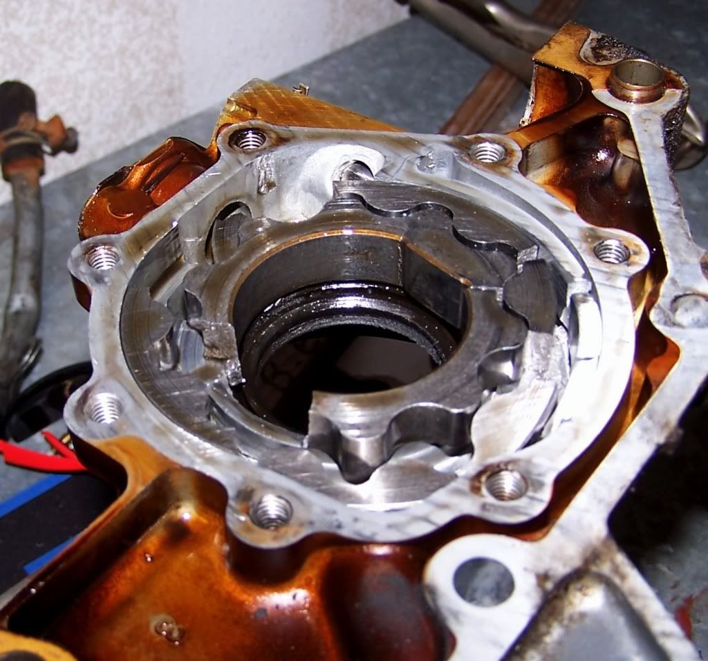
Simply changing the language and redescribing the metal from a thin section rotor to a thin walled annulus will assist understand what is actually going on.
For example, examining the annulus of this pump it is hard to imagine how mating with a low frequency linear vibrator is root cause of it so buggered by a clearly painful experience.
Having said that close examination of the annulus reveals it is not designed to take heavy duty excitation and impulsive loads so no surprise things could end in tears anyway.

Furthermore this paper rejects Yankee nonsense that vibration turns the metal in rotors to glass when this paper has proven via Aussie nonsense that the metal would turn to rubber.
Instead the paper joins the dots to forceful brutal steps being the pump trying to stop the nose of the crank from turning it back and forth in a rhythmic dance.
One would normally expect that the gerotor annulus is so light it can easily dance together in harmony with the crank nose buried inside it in a tight embrace.
But what happens when the relationship turns abusive and instead the gerotor annulus is raped and pillaged by the nose of an all powerful and unrelenting crank.
Imagine the poor annulus fighting back unwilling to dance the dance of the crank nose and tragically is torn apart in the brutal struggle between them.
Is there something getting the gerotor annulus so uptight in the pump, unable to relax, to willingly turn in sync back and forth in harmony with the relentless throbbing of the crank nose ?
Maybe we don't understand the root cause is rotor abuse by the crank nose. Maybe we simply don't realise the pressure the pump is actually under from such abuse.
Disasters don't just happen; so treat the annulus as a black box and investigate it. Countdown the chain of critical events that happen in the final Seconds from Disaster!
Invitation is now given to test CAE, Claim, Argument and Evidence generated below to prove or disprove the "chatter hypothesis".
14.0 Listen to the Oil Pump Chatter
Maybe the pump cavity itself is subject to transient pressure lasting just milliseconds not picked up in gallery pressure gauges ?
Is there a clue to be found in ways sought to manage steady state gallery oil pressure as distinct from oil pump cavity pressure via relief valve modification.
An observation made for this modification is the OEM relief valve on race cars is said to chatter....what rpm is the chatter ? What is driving spikes in pressure to cause it. ?
Lets make a distinction between cavity pressure and gallery pressure because of pressure lost getting through the gallery to the pressure sender mid point on the engine.
We don't measure actual oil pump cavity pressure also seen at the relief valve due to the short flow path between them. Instead we measure the smoothed out steady state pressure.
The sender is saved from pressure spikes in the pump cavity by an orifice tube which so happens to be the gallery under high flow.
The sender is saved but the relief valve is not. The relief valve gets hammered by any pressure spikes forming in the pump cavity.
Spikes are caused either by:
- the pressure ripple from passing of each inter rotor oil pocket across the divide between the low and high pressure sides of the pump.
- pump pulse flow from torsional oscillation displacement of the pump in the direction of flow.
Is chatter from pressure ripples or vibro-impact pulses in pump flow. ? Listen to The Voice of an OEM.
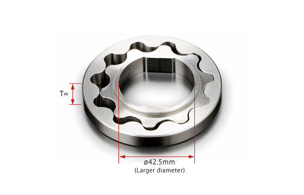
That voice advises pressure ripples at 167 Hz/1000 rpm in a 10 tooth dríven inner rotor or annulus mating with a big nosed crank.
A big nosed crank with say a 380 Hz fundamental mode mating with the annulus of such a pump could therefore get a bit excited at 2280 rpm and its multiples.
That begs the question....what is the chatter frequency vs engine rpm relationship ?
So the 1st test of the hypothesis is whether the relief valve can react quickly enough to relieve flow spikes or pulse from pump speed change from transmitted crankshaft torsional vibration velocity.
In other words what flow pulse will dead head against the relief valve if the response time for the relief valve is slow depending on the relief valve orifice configuration ?
The 2nd test is whether sloppy fit to the crank could transform linear torsional vibration of the crank into sharp non linear vibro-impacts of even higher velocity to savagely pulse the pump.
The 3rd test is whether the gallery to the sender and beyond is long/small enough to act like an orifice tube to a flow pulse to build significant pressure pulse in the pump cavity.
In other words what flow pulse will dead head against the gallery as an orifice tube?
The 4th test is whether the pump cavity is sufficiently stiff to build significant pressure from expansion resulting from dead heading of the flow pulse.
The 5th test is whether the oil is sufficiently stiff to build significant pressure from volume compression of entrained air resulting from dead heading of the flow pulse.
Imagine this: The annulus is light and responsive enough to expect any oil displaced by it vibrating, is not enough to add significantly to instantaneous flow.
However non linear impact to the annulus can spin it quick to produce enormous flow for an instant.
Enormous flow can dead head and produce a lot of resistance to flow seen as potentially damaging pressure spikes.
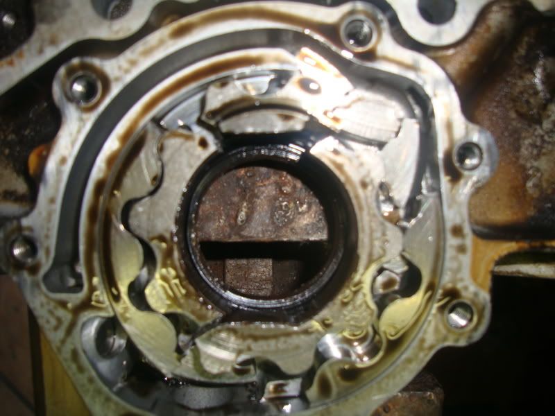
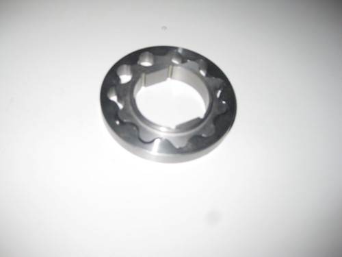
It is hard to imagine a worse thing for an oil pump inner rotor as an annulus or ring being forced open by strong impact.
Take a good look at its annulus or ring, than imagine a sloppy fitting two sided stub nosed crank banging on it mercilessly.
The resultant is a twisting moment or torque resisted by a pressure spike and two large opposing forces tearing open a thin walled sloppy annulus as shown:

Imagine full chorus Hallelujah resonance + clearance impacts like a a vibro-impact gun forcing open a sloppy annulus momentarily held by instantaneous dead headed flow spikes.
Imagine the relentless annulus opening force stretching open the thin inner wall of the annulus all the way to its breaking point and beyond.
Now one way to force the annulus to move quick motions without damaging its thin walls is to use a spline drive instead. This eliminates the annulus opening force.
This spline drive on Toyota OEM 6 cylinder 1JZ and 2JZ stops impacting the annulus of their oil pumps and thus damaging pressure spikes even at Full Chorus Hallelujah resonance.
Japanese tuners offer retrofit spline couplings for Nissan RB owners.

For Japanese 6 cylinders, Full Chorus Hallelujah resonance causing high pressures from dead headed flow is likely cause of the large prying force generated.
This is because high instantaneous flow can be imagined very high and beyond the capacity of small diameter pipes, hoses, galleries, orifices.
The stiffness of the oil volume in the pump cavity is also likely higher with entrained air slightly precompressed by higher steady state pressure.
High cavity stiffness experienced by a dead headed flow spike can amplify the pressure of the spike, creating extreme tension in the screws holding on the cover.
The tension stretches the screws beyond yield causing loss of screw pretension allowing them to come loose as reported on some 6 cylinder engines.

Properly tightened fasteners don't magically "vibration loosen", they lose clamping force first by yielding in the joint overcoming pretension. In this case yielding is likely screw stretch.
Flow pulse/ripple generates cavity pressure spikes and thus prying force and thus high bending fatigue stress in the thin inner rotor as it traverses the inlet and outlet chambers.
.A lack of robustness in the design of the pump/drive, has established reasonably foreseeable preconditions for failure from point loading section of the inner rotor as a weak beam.
Such preconditions allow critical damaging force to build in a set and sequence of circumstances that can be imagined just Seconds from Disaster.
So imagining how the pressure spikes cause problems, gives rise to a solution preventing the pressure spikes inside the pump in the 1st place.
This is done by eliminating the pressure spikes associated with resistance to dynamic flow.
If a BP was a 6 cylinder exposed to Full Chorus Hallelujah resonance, and was a sloppy fit to the crank then it might lead to the following approaches:
The most robust approach might be use of an externally dríven oil pump like a dry sump system for example.
Another robust approach is elimination of the forces prying open the sloppy annulus by using a Toyota 2JZ style spline drive.
Another approach is elimination of the possibility of vibro-impact by managing crank nose to pump rotor slop by shimming out clearance.
Another approach used by Mazda on the later SVT engine is dramatically improved relief valve performance with larger relief passage and fast response vent design.
 __
__
______BP Oil Pump early (4mm wide relief passage + 1x10mm vent hole) ______________BP Oil Pump late (SVT) (6mm wide relief passage + 2x15mm vent slots)
Another robust approach is not directly fixing slop but reducing its pressure effects, is remote mounting a high flow relief valve via sizable resilient hose.
Another robust approach is redesign of the pump cover and fixings to be less stiff to incorporate an accumulator effect so that the effective"modulus" of the pump cavity volume is less.
Another approach is greater cavity resilience by mods to the gallery passage. It could be bell mouthed, bored and a length of hose/mini accumulator replacing its external plug.

A perhaps less robust approach is use of higher toughness high tensile billet rotors to delay the inevitable, even more so should there be a tighter tolerance fit to the crank. .
(Note this supplier has recently packaged this Solution into the later SVT relief valve housing as a more robust Solution.)
A less robust approach not fixing slop but reducing its pressure effects is to retain the OEM TVD. The resonant peak to peak twist at the oil pump is likely to be less in comparison with a solid pulley.
Similarly a Performance TVD can be used. However in a BP 4 cylinder oil pump, saved from Full Chorus Hallelujah resonance it is hard to imagine a better practical outcome than with the OEM TVD.
15.0 Ponder these Inescapable Conclusions
It is hard to find demonstration of clear cause and effect for each of the complex Problems that suppliers of TVD's claim to fix.
Suppliers claim to reduce vibrations and it is clear they do. But if no benefit is gained other then "it's now so smooooth" is that a placebo for imagined issues ?
TVDs are not a "One Size fits All" Solution. Furthermore vibration is only a Problem needing a Solution if specific vibration is specifically a Problem.
To know if a vibration Solution is required is often to Quiet down and Work the Problem people with a bit of rocket science coming in handy.
So maybe vibration is not a Problem, maybe the only Problem for a worked BP could be risk to the oil pump.
A risk of excessive instantaneous dynamic back pressure spikes in the oil pump cavity and resultant excessive distortion of the inner rotor to ultimately fracture it !.
Torsional vibration is really just a precondition for crank failure, albeit an important one in V8s and in line 6's but not Fast Fours.
In the case of BP and other Fast Fours free of Full Chorus Hallelujah crank resonance, it is hard to find compelling CAE to prosecute the case for TVD's for crank protection.
TVDs may be the best friends of V8 and inline 6 enthusiasts, but not of 4 cylinder enthusiasts whose world it seems is not in need of them.
The argument standing up against scrutiny for a Performance TVD on a BP is in order to comply with rules in some motorsport jurisdictions.


