Next project was an electric window timer.
I really hate that the windows shut off with the ignition in most cars. I figured if Ford can let the windows work in a Falcon for 5 mins after the IGN is off then I can do it in my cars.
I first built one of these timers for my X-Trail from a circuit posted on the Australian forums. It has worked flawlessly for 4 years now. It works out to about $30 if you have to buy wire and all crimp connections.
FULL DISCLOSURE:I take NO responsibility for your attempt. Any damage you do to your car is your fault. This is how I did it and it works for me. I worked as a mechanic for Ford for close to 10 years.
Full credit goes to Revhead Kev and Naff for the original circuit design found here,
http://baustralianxtrail.runboard.com/t124815,offset=40So go ahead and follow their write up to build the board. Once you have it to that point things change a bit to get it to work in a 5. I used a larger case for the timer as I wanted the relay mounted inside the case to keep things neater up under the dash.
You will also need 2 blade fuse holders, a couple of 30A fuses and a 4 or 5 pin relay in addition to the parts list in the link. Depending on the relay you use you can forget about the 4.5mm male and female connectors.
Wire colours make life easier but aren’t that important so long as you label everything properly. I just used up wire I had laying around in the shed.
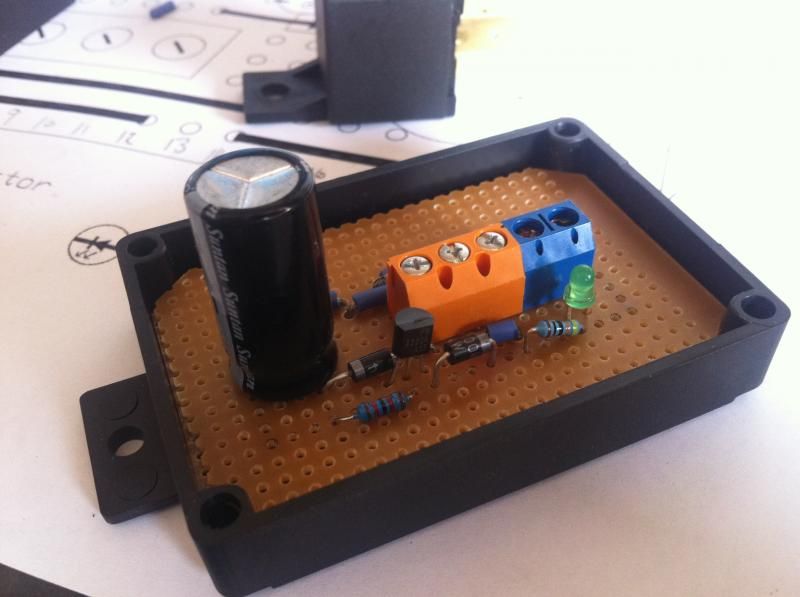
So from left (the blue slots) to right (orange). The wires on the board need to go to the relay or be given tails and labelled like this.
1. 10cm wire with a female terminal onto relay post 85
2. 30cm wire terminates with an eyelet terminal. Label this wire as vehicle earth.
3. 10cm wire and a 30cm wire into a female terminal onto relay post 30 the longer end terminates with a female terminal. Label it Battery 12v.
4. 10cm wire with a female terminal onto relay post 86
5. 30cm wire terminates in a male spade terminal. Label it window fuse Acc hot.
6. 30cm wire terminates in a male spade terminal. Label it fuse window supply.
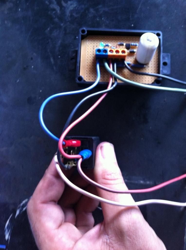
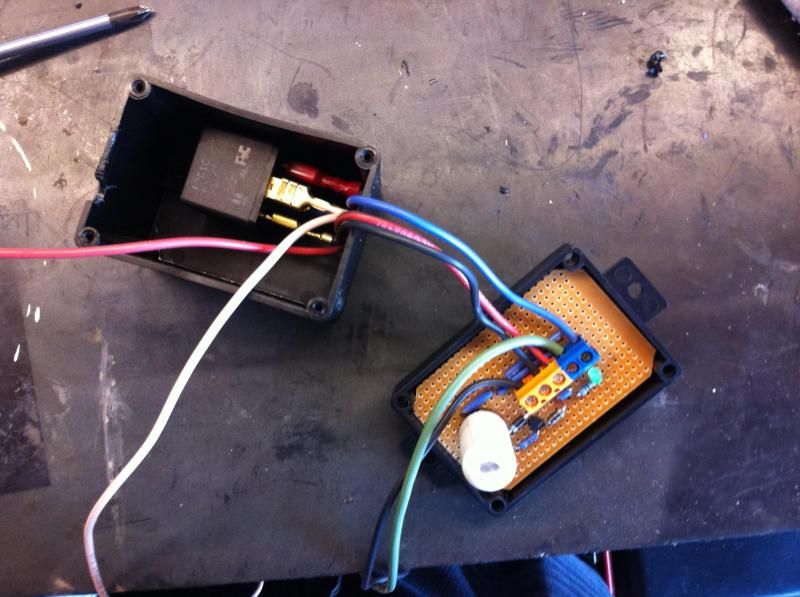
Now tuck the relay into the case and hang your 4 tails out one end. You will have to cut a relief in the box for the wires.
Climb under the dash and have a look at the fuse panel. Just above and to the left of the panel there is a weld nut in the body of the car. This is where I bolted the box to secure it. I also attached the wire labelled vehicle earth to this bolt.
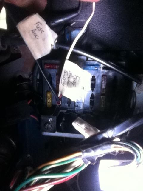
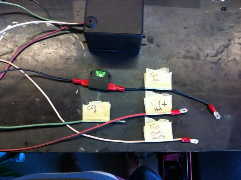
The green 30 amp fuse top row second in from the right is for the electric windows. Pull the fuse and confirm with a test light which pin is live with the key in the ACC position. In my case this was the top pin. Grab one of your fuse holders and add it to the end of the wire marked ACC 12V and then push it into this pin.
Into the other empty pin in the window fuse insert the wire labelled fuse window supply.
The final wire marked 12V hot will get the remaining fuse holder attached to it and then run a wire from this fuse along the sill up and into the boot attaching it to the “+” battery terminal.
And that’s all there is to it. Turn the ignition on and then off and test your handy work.
Note: The LED on the board stays lit while the circuit has power available so if you want you can solder tails onto the led and mount it outside the box through one of the blank switches for example to let you know if the windows are still live.
I did this the first time but if the LED is too bright it will drive you nuts…


