TICO the SE

Chat to do with your MX5/Miata/Eunos Garage Ride(s).

Moderators: timk, Stu, zombie, Andrew, The American, Lokiel, -alex, miata, StanTheMan, greenMachine, ManiacLachy, Daffy

User avatar
Roadrunner
coyotes after you
Posts: 1111
Joined: Tue Nov 06, 2012 9:02 pm
Vehicle: NB SE
Location: Newcastle

Re: TICO the SE

Postby Roadrunner » Fri Mar 14, 2014 8:49 am

Crapweasel wrote:
100 posts Roadrunner!! 8)

Here's a theoretical top speed in each gear using 3.636 rear end like we have:


Awesome! And my prize is correct information on the internet! Thanks :beer:
MeepMeep

Magpie
Speed Racer
Posts: 7468
Joined: Fri Feb 11, 2011 12:49 pm
Vehicle: NA6
Location: Purga, QLD

Re: TICO the SE

Postby Magpie » Fri Mar 14, 2014 9:36 am

A good source for gearbox ratios is http://www.miata.net/garage/KnowYourCar/S8_Gears.html

In my NA6, with 182 RWHP, 6 speed and 4.1 diff I can confirm that 1st is not used for very long :) I get 110 in 3rd at 8,000 and about 60 in 1st.

User avatar
tomli123001
Forum sponsor
Posts: 385
Joined: Wed May 08, 2013 11:18 pm
Vehicle: NB SP
Location: Brisbane
Contact:

Re: TICO the SE

Postby tomli123001 » Fri Mar 14, 2014 10:37 am

Then what explains the reason Charlie's and ZoomZoom's used 4.3 in their mega horse power mx5?
Jason's view is that you never use 1st much, as it will never get to boost much even if reved out to red line. He reckon is better off to have a lower gear ratio and accelerate more in 2nd once the 1st has got the car rolling.

Honestly I always believed in 3.6 as the best for turbo before.
I was going for a 3.9 in the rebuild as I did feel my gear was too tall compared to my last NA. But I ended with 4.1 now after Jason's strong recommendation.

I have been offered a free rebuild this time round, as mx5 plus was last person to touch the diff last Friday (they think may be over fill of oil, still a mystery). So I decide to experiment on this.
NA6-Rolled off Mt Nebo
NB SE-Sold for investment property deposit, then crashed by the buyer months later
Now Black NB SP #31.

sailaholic
Speed Racer
Posts: 3511
Joined: Thu May 19, 2011 3:38 pm
Vehicle: NA8
Location: Brisbane

Re: TICO the SE

Postby sailaholic » Fri Mar 14, 2014 2:12 pm

Tim and Carlie both had it for track times. They didn't care about 1st and 2nd. Tim has now changed to a 4.1 as he was hitting the rev limiter in 6th at lakeside. More top speed now but a little slower out of corners.


Sent from my iPhone using Tapatalk

User avatar
Kev05
Racing Driver
Posts: 1456
Joined: Sat May 19, 2012 11:24 pm
Vehicle: NB8A
Location: Brisbane

Re: TICO the SE

Postby Kev05 » Thu Mar 20, 2014 5:18 am

Is the car back on track? i.e problem fixed?
User avatar
tomli123001
Forum sponsor
Posts: 385
Joined: Wed May 08, 2013 11:18 pm
Vehicle: NB SP
Location: Brisbane
Contact:

Re: TICO the SE

Postby tomli123001 » Sat Mar 22, 2014 5:56 pm

Kev05 wrote:Is the car back on track? i.e problem fixed?

Yes, finally got it back this week. and a lot has happened since actually :mrgreen: (good excuses to tell my wife spare parts need to be ordered and the car is stuck in the shop for a week. )
NA6-Rolled off Mt Nebo
NB SE-Sold for investment property deposit, then crashed by the buyer months later
Now Black NB SP #31.

User avatar
tomli123001
Forum sponsor
Posts: 385
Joined: Wed May 08, 2013 11:18 pm
Vehicle: NB SP
Location: Brisbane
Contact:

The broken diff

Postby tomli123001 » Sat Mar 22, 2014 6:04 pm

All right, so here is what that grinding sound was.


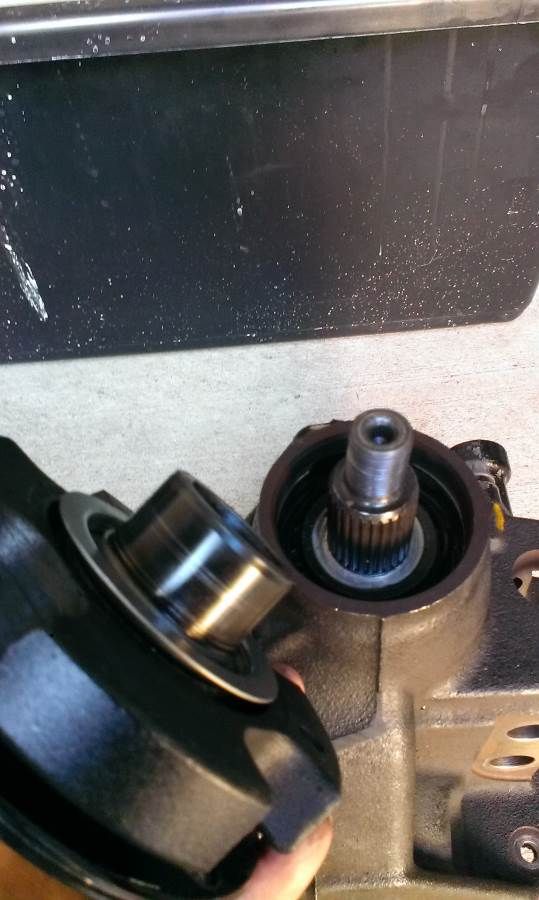
The theory goes like this, after it came back from the diff rebuild. The car was on the hoist, which is not leveled when the diff fluid was filled. An overfilled diff caused too much heat and pressure. When it blew the sealant and seals, a bit major leak took place. The bearings in the video got starved of oil and the damage was done. The bearing was damaged so badly, it integrated itself into the casing and not removable. So a whole new diff front casing assembly was required. Lucky, was all covered by MX5 plus.

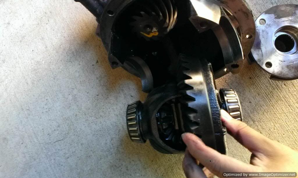
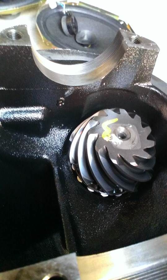
For those of you interested. Here is what is inside the diff. The gear after the pinion bearing and the big round gear are what decides the ratio. Mine is now a 4.1 ratio, while stock late NB is 3.6.

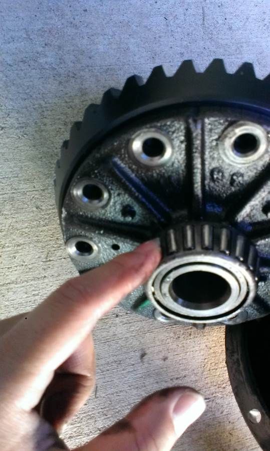
Then it goes to the center, which connects to the axles via the roller bearings there. Luckily my diff center was still bathed on inspection, so the actual LSD part is unharmed. The pictures here are from the donor diff, which gave me the front casing. My SE housing and the axles and the LSD center are reused now after rebuild.

Dead bearing there
Image

Pinion gear
Image

The rest pinion gearing and the rest of the diff internal (the donor diff open center)
Image

The roller bearing here, which connects to the axle (driver side)
Image
NA6-Rolled off Mt Nebo
NB SE-Sold for investment property deposit, then crashed by the buyer months later
Now Black NB SP #31.

User avatar
tomli123001
Forum sponsor
Posts: 385
Joined: Wed May 08, 2013 11:18 pm
Vehicle: NB SP
Location: Brisbane
Contact:

Re: TICO the SE

Postby tomli123001 » Mon Mar 24, 2014 1:15 pm

speed freak wrote:Looking good :D

How good are the braided brake lines hey? I couldnt believe the difference it made when I got mine put on.

With the innovate oil temp/press gauge does it come with the 'normal' screw in type sesnors that would go into say a oil filter relocation kit port?

Also where abouts have you routed your wires for the gauges? I cant work out how to get them through the firewall and into the engine bay. Meaning I cant find a rubber grommet that leads to behind the dash somewhere.
Updated now below in my next post.
NA6-Rolled off Mt Nebo
NB SE-Sold for investment property deposit, then crashed by the buyer months later
Now Black NB SP #31.

User avatar
tomli123001
Forum sponsor
Posts: 385
Joined: Wed May 08, 2013 11:18 pm
Vehicle: NB SP
Location: Brisbane
Contact:

new engine bay and gauges install

Postby tomli123001 » Mon Mar 24, 2014 3:01 pm

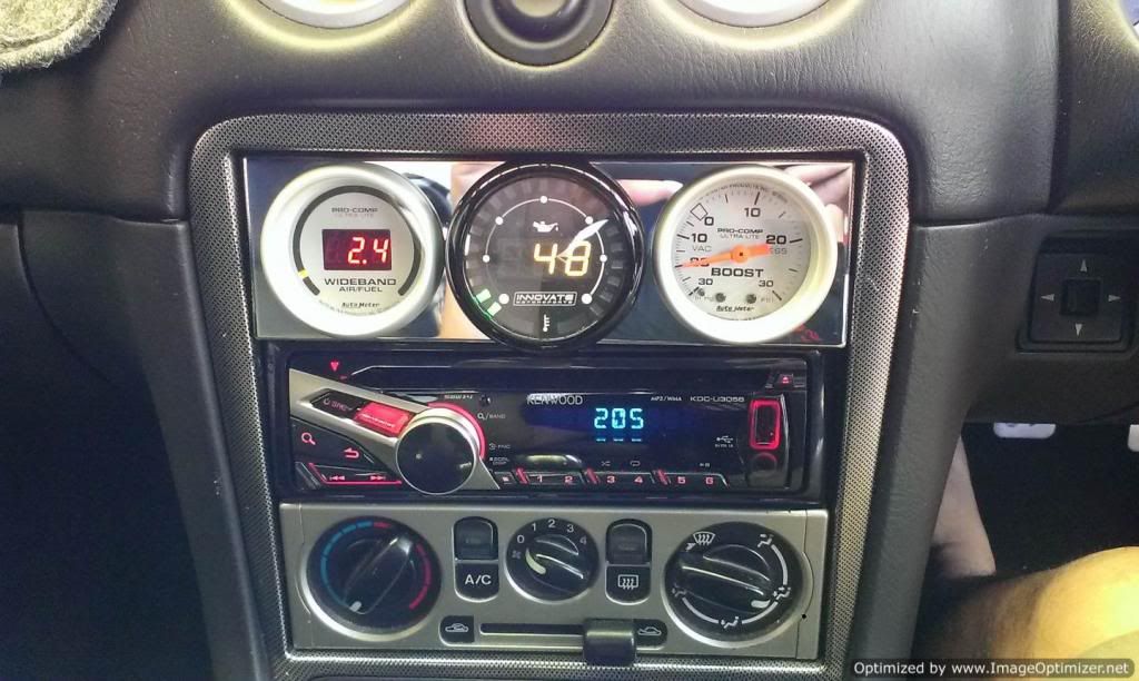
So now all my gauges work properly like below.
I thought I might share how they are plumbed.

Working gauge cluster
Image

I saw most people install things in the air conditioning duct. But I went with the center headunit area install, which seems much easier.

1. Boost gauge install.
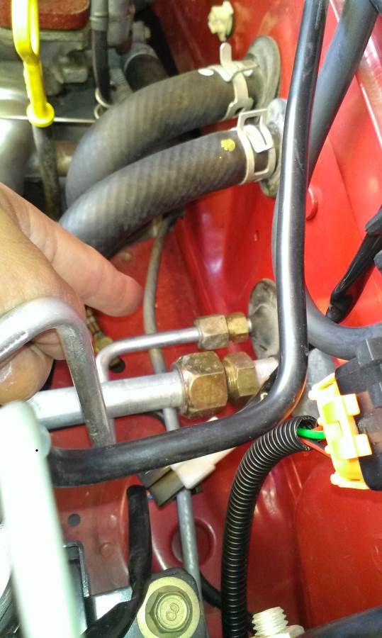
You will need this T piece to read the pressure at the inlet manifold.
Image

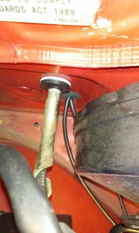
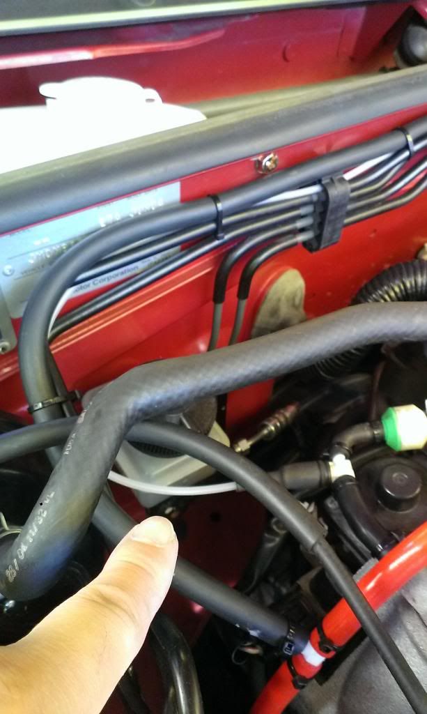
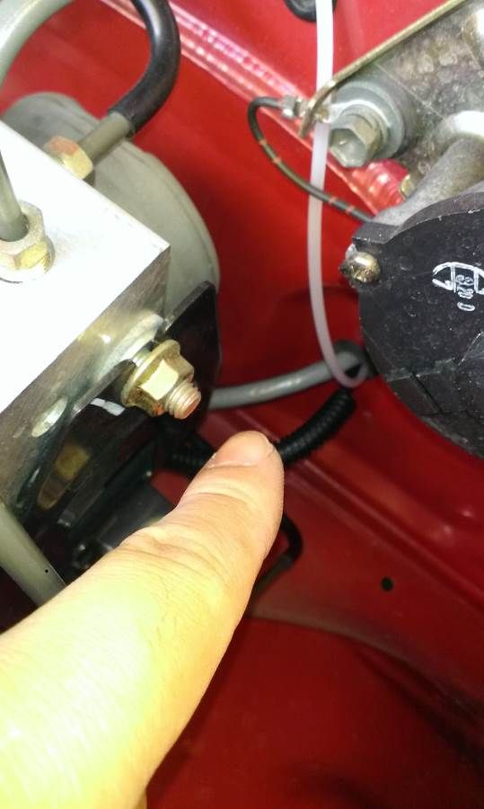
There are 2 holes on the firewall, one in the driver end and one at the passeger end. Be careful not to press this hose too hard to crimp it through the hole. For me, I am using the hole via the passenger end, due to not enough room in the driver side hole after my oil pressure/temperature wires through it already.

So I run the vacuum line across the metal line on the firewall as you can see in the photo. And enter back into cockpit here at passenger side:
Image


2. Wide band O2 install
If you are still on the stock SE down pipe, you will need to weld a bung onto it.
I got an SMB unit. They offer to do the weld, but I have been advised by Jason to do the weld with them when I install the exhaust, because it is easier to adjust the weld location when on the job.

The sensor wire comes out the same hole as the above photo with the boost gauge vacuum line. (the grey thick wire, I am talking about.)
Then it will run easily to the down pipe at the back of the engine bay.
Image


3. Oil pressure and oil temperature gauge install

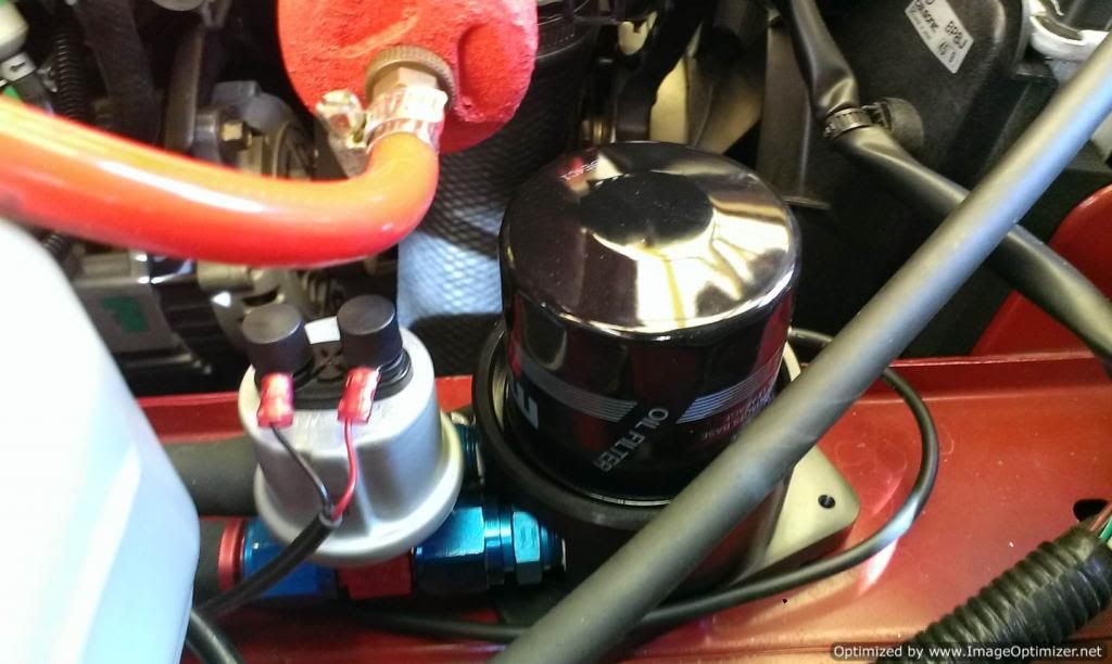
I went with the easier solution. I bought a Thomson unit from the US for my oil filter relocation kit, which has the hole for oil temperature sensor already. Jason told me that, if not, they can drill a hole in your oil sump drain plug and mount sensor there. But it will be kinda inaccurate due to measuring sump oil temperature instead. When ordering, make sure you tell Thomason you need the model for MazdaSpeed Miata.

MX5 Plus makes and stocks a special adapter for the pressure sensor mount to go with the Thomason kit. Here is the installed photo. The 2 lines go back to the car via the hole on the driver side.
Image

The oil pressure adapter is on the left
Image


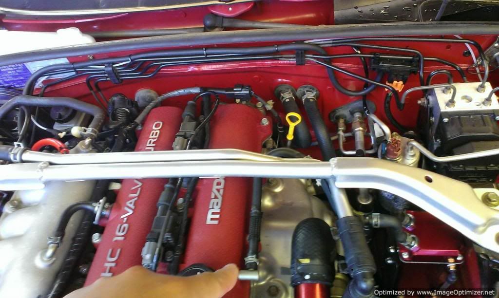
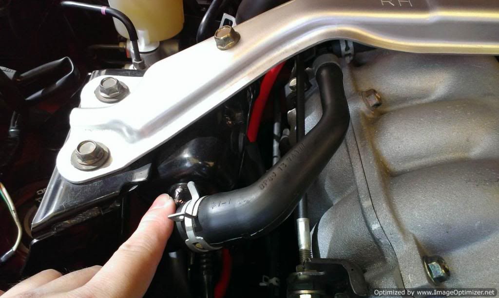
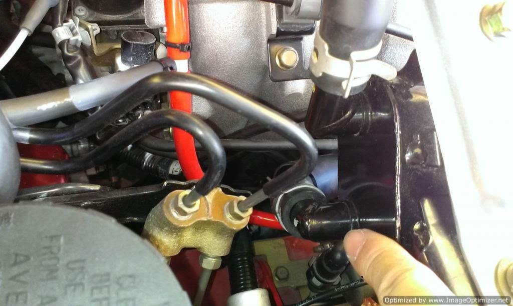
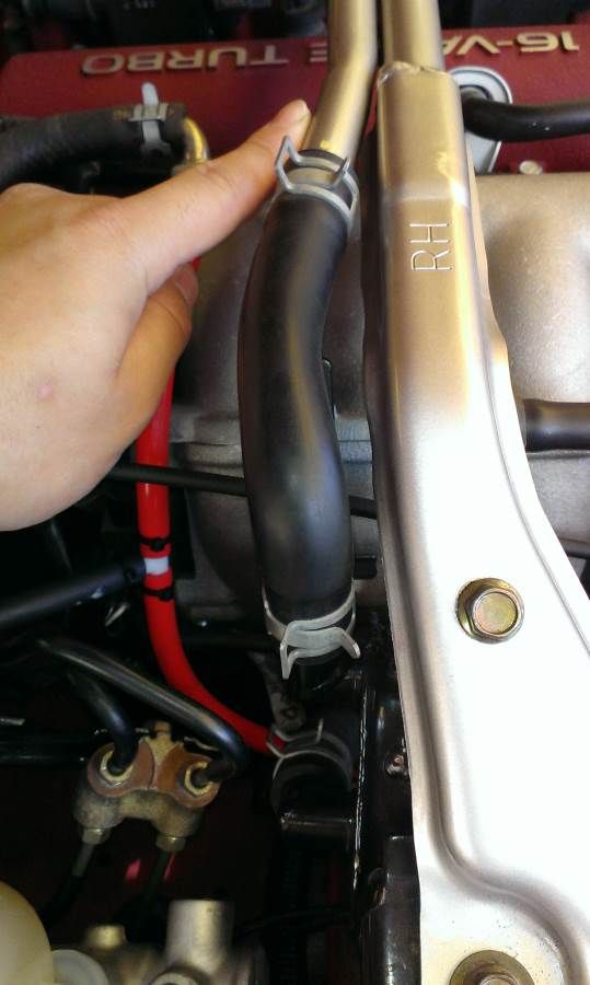
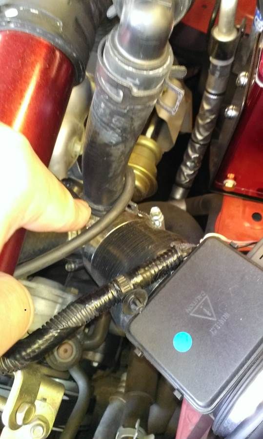
4. Special SE catch can set up
I really like the SE catch can factory actually. Because the hoses travels inside the strut brace. The can has a plumbing with the sump to drain the oil back, rather than manually emptying it.

However, the down side is that it is tiny and a lot of racers say when at high g cornering the flat and high ome catch can can have oil easily flow via the strut brace tower brace hose straight into the air intake and oil your intake parts.

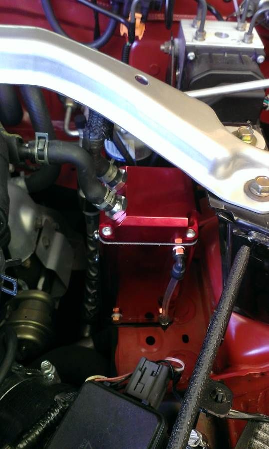
So here is mine set up with a can in series with the factory items. The can and bracket are supplied by Jason at a good price.

- the oil vapor leave the CAM cover here.
Image

- it now goes straight into my new catch can via the hole closer to the front of the car.
Image

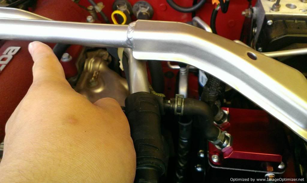
- The gas next leaves the 1st catch can via the hose closer to fire and into the thicker part of the strut brace (inside the hose)
Image

- The gas now enter factory catch can
Image

- The oil is drained into the sump
Image

- the gas is now going back to the intake side via the thinner part of the strut brace. No hose seems like, just inside the metal tube
Image

- now back to the air intake before turbo
Image

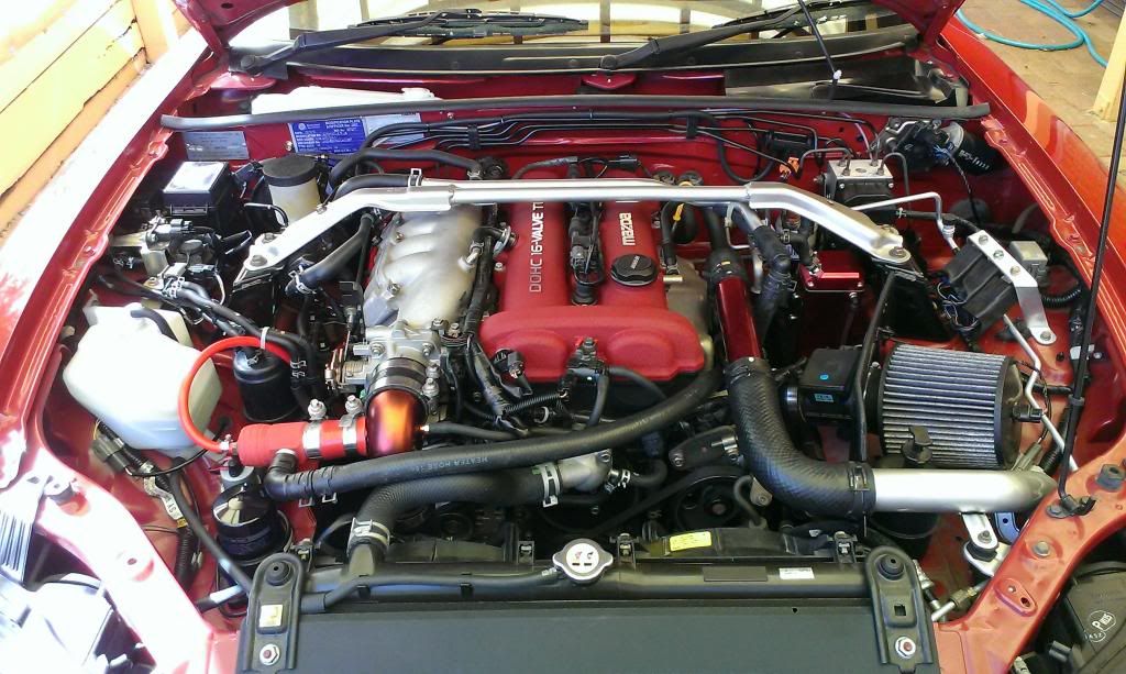
Of course, I installed the washer bottle relocation kit.
Here they are and the new engine bay look.

Image
Image
NA6-Rolled off Mt Nebo
NB SE-Sold for investment property deposit, then crashed by the buyer months later
Now Black NB SP #31.

User avatar
tomli123001
Forum sponsor
Posts: 385
Joined: Wed May 08, 2013 11:18 pm
Vehicle: NB SP
Location: Brisbane
Contact:

Re: TICO the SE

Postby tomli123001 » Mon Mar 24, 2014 8:48 pm

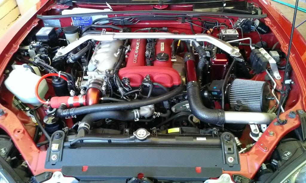
After Lockiel pointed to me that I did the relay boxes adapters wrong behind the air filter, I corrected it this afternoon. So now the engine bay looks like this now.
Image
NA6-Rolled off Mt Nebo
NB SE-Sold for investment property deposit, then crashed by the buyer months later
Now Black NB SP #31.

User avatar
tomli123001
Forum sponsor
Posts: 385
Joined: Wed May 08, 2013 11:18 pm
Vehicle: NB SP
Location: Brisbane
Contact:

Excede installed

Postby tomli123001 » Mon Mar 24, 2014 9:15 pm

I have got the car back from Chiptorque recently after deciding to use the SE as a daily driver only.
I am now finally in the 150wkw club. The power is rather smooth and far better control than before with just manual boost T.

Chiptorque used the factory solenoid here in the install and a pigg back configuration of the Excede computer, designed and made by them locally. Very different to what I thought, Chiptorque actually has many agents in different cities and have open source code on request, so other tuners can work on the car instead of going back there all times.

You can see the solenoid in engine bay photo.
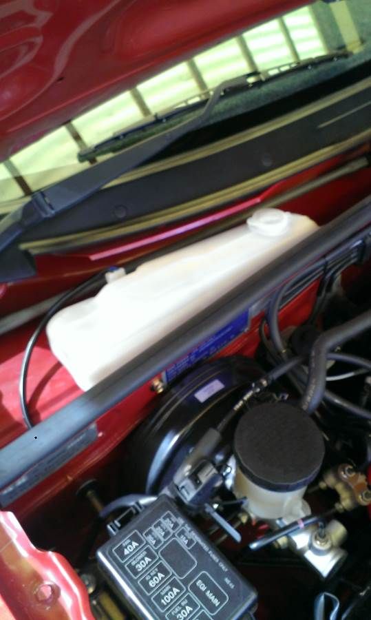
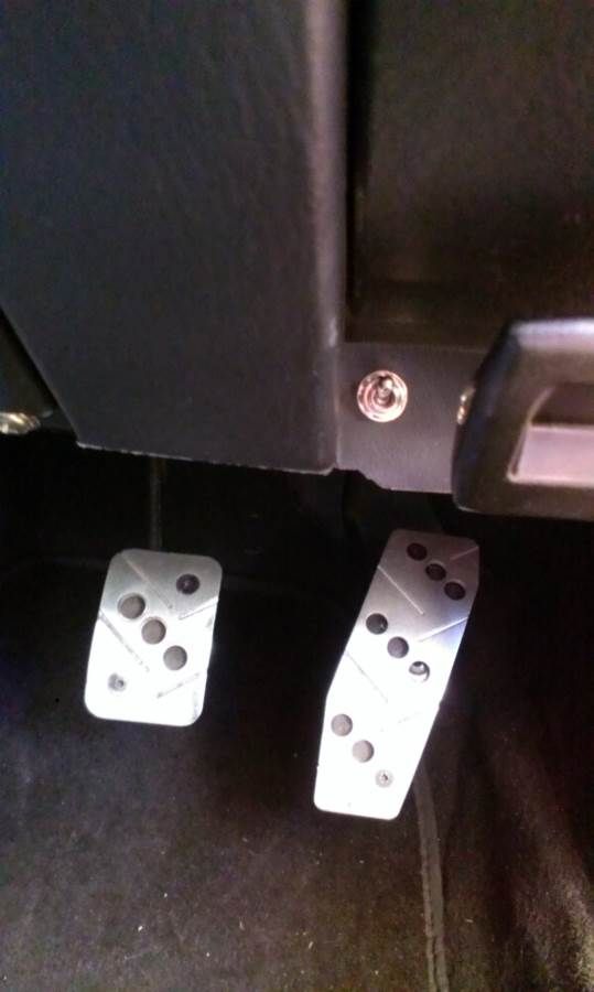
I got a stealthy switch also here to adjust between 98 and 95 octane fuel. It can be switched during driving and essentially change the boost pressure.
Image

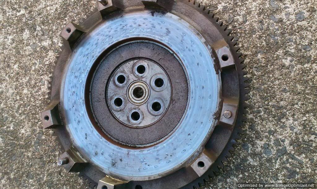
Here is a photo of my old 1.8 flywheel. You can see the black dots on the surface from the wore out clutch slipping away. It is much heavier than I thought.
Image

I did a few other little things also.
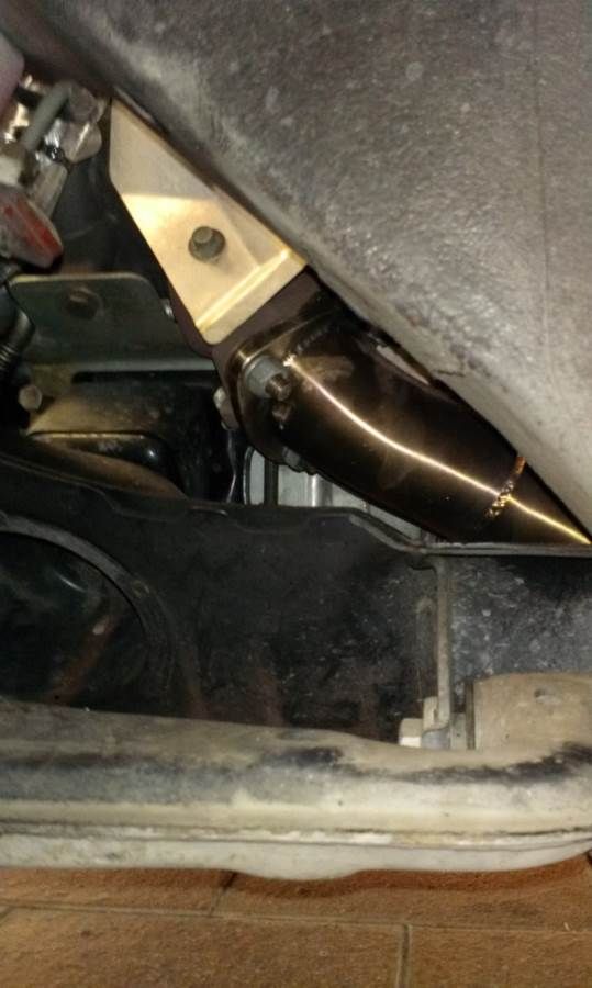
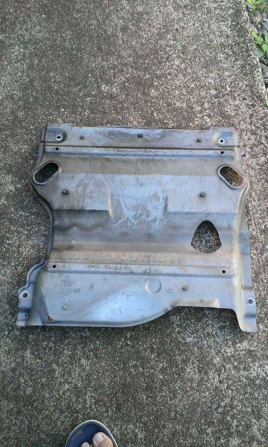
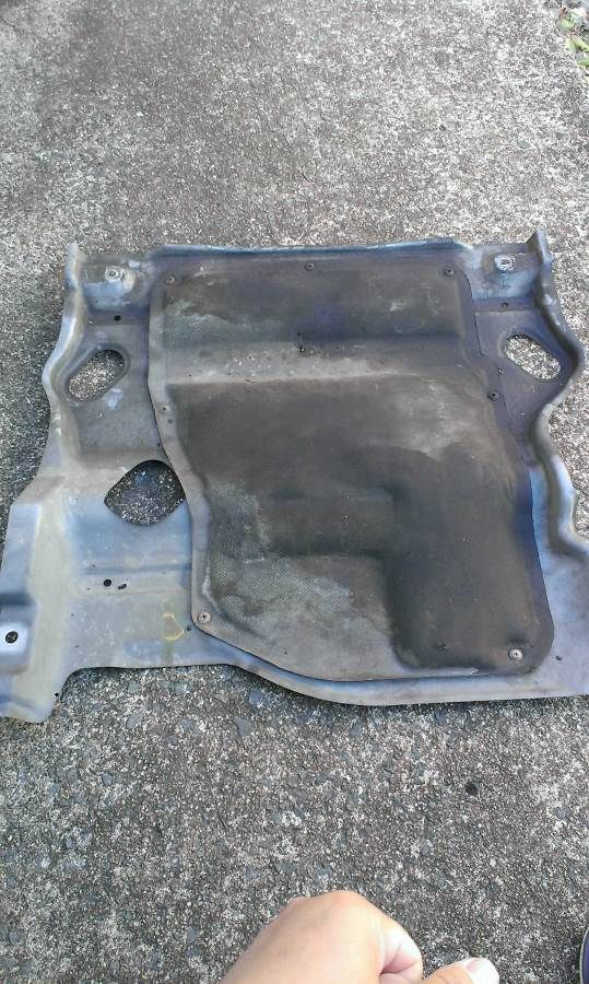
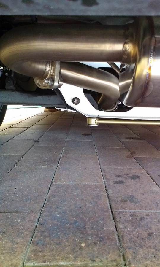
Installed the SMB down pipe, but it will prevent you installing the SE shielding underneath afterwards. So it has to be removed and luckily it is not structural at all, but for noise cancellation.
Image
Image
Image
You can see the soft stuff in the back of the metal.

After the SMB mid pipe is installed, it is not matching the factory or Racing beat muffler angle very well. It actually puts my tip out of center, so I am visiting mx5 plus to weld the tip pipe later this week.
Image

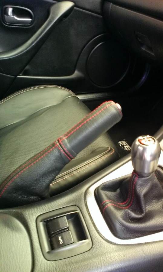
I added an ebay matching hand brake lever leather cover also.
Image

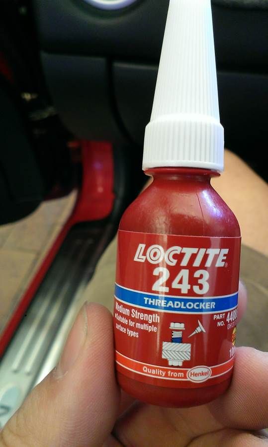
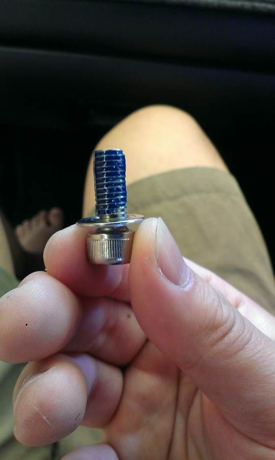
Finally I fixed up the annoying kept coming off loose hardtop bolts with some threadlock. First time used it, I think I put a bit too much on the bolt here.
Image
Image

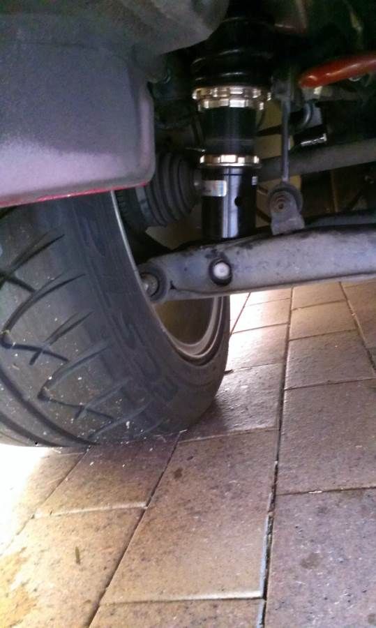
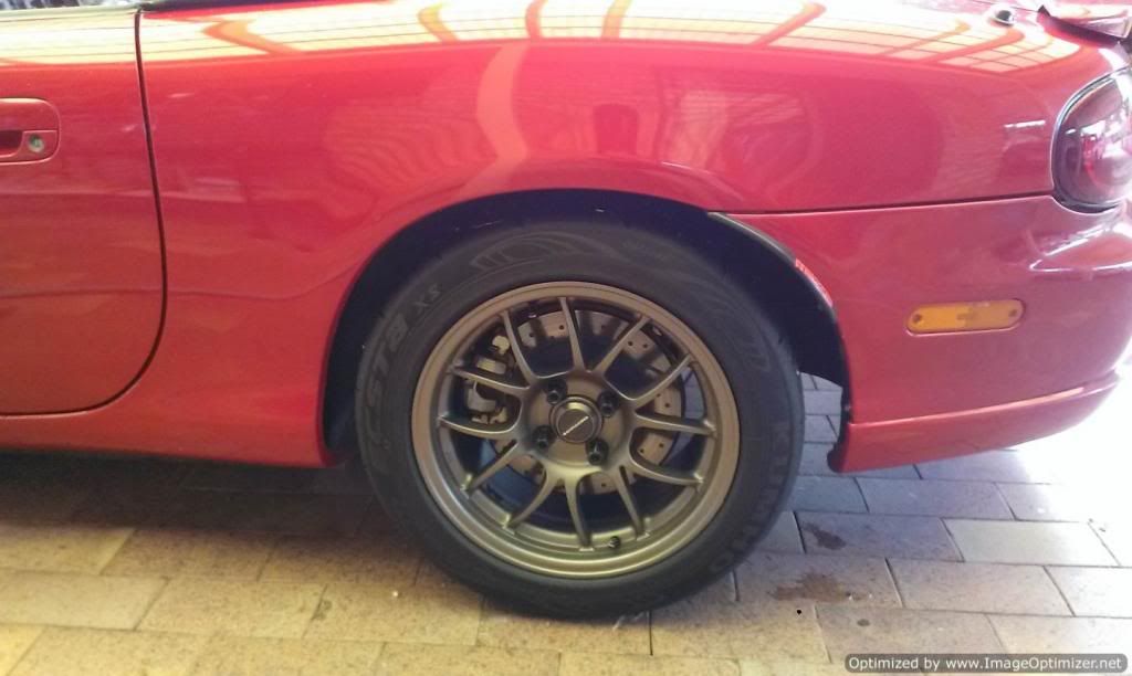
Finally, I did my suspension height to raising it, after Lockiel protesting this in my thread a number of times and reading the benefits of higher rear end. After all, I can now driver through Macca's speed bump now no problem at all.

There are 3 rings in total on BC coilover. I call them ring 1, 2 and 3, from top to bottom. The thread which the spring covers should never be changed, as this will reduce your travel. The ring 3 at bottom is locked onto the shock lower body. The thread in and out of the ring 3, is what adjusts the height. In my case, to increase the ride height, simply put the lock ring tools at ring 2 and 3. Move the ring 2 anti clockwise and the thread will move out of the ring 3, giving me more height. At this time, the ring 1 acts as a lock ring, so ring 2 will not move itself up and down.

To lower, use ring 1 and ring 3, then ring 2 becomes the lock ring preventing ring 1 moving down. You just need to spin the ring 1 clock wise to put more thread into ring 3.
I could not achieve factory ride height for daily drive with BC however. Because when going too high, there will not be enough thread left in ring 3 and this make the shock less stiff structurally and it may strip the remaining thread before an epic fail. This really explains why coil is much better solution than just a shorter spring on unmatched stock shock. Because the shorter spring reduces the overall damper travel, but BC coil over can change height without touching the travel, so you could get a really low car, but still with full suspension compliance.
Image

raised rear height now. Looks very 4wd to some of you here, probably due to the angle of photo
Image

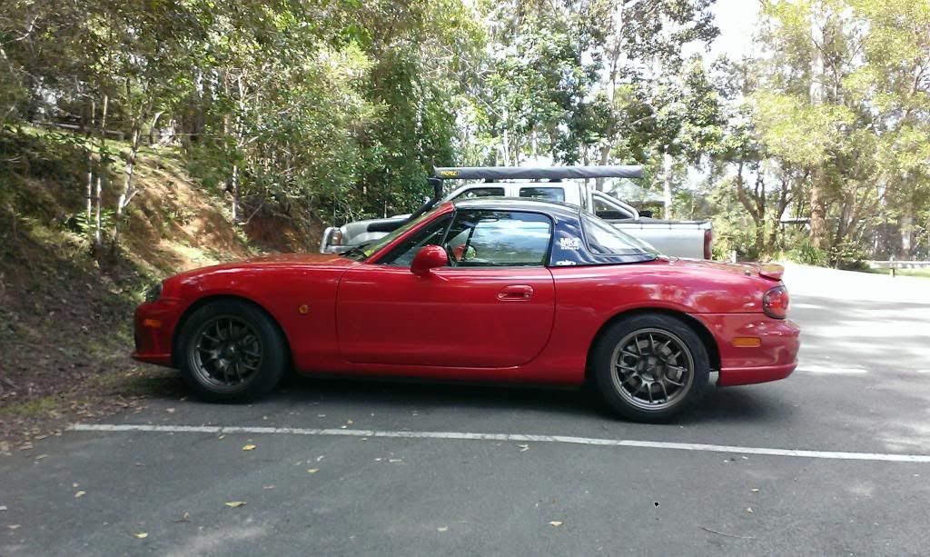
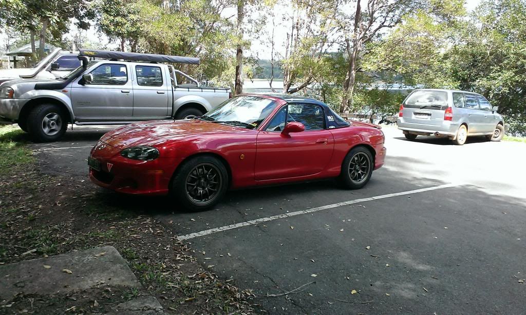
So here is what the car looks now on my weekend Montville drive.
Image
Image

and spotted this when taking photos
Image
NA6-Rolled off Mt Nebo
NB SE-Sold for investment property deposit, then crashed by the buyer months later
Now Black NB SP #31.

User avatar
Lokiel
Forum legend
Posts: 4126
Joined: Thu May 28, 2009 2:39 pm
Vehicle: NB SE
Location: Brisbania

Re: Excede installed

Postby Lokiel » Mon Mar 24, 2014 10:28 pm

tomli123001 wrote:Finally I fixed up the annoying kept coming off loose hardtop bolts with some threadlock. First time used it, I think I put a bit too much on the bolt here.

Yup, that bolt aint coming out in a hurry (or maybe ever?)
Typically you only need a drop - when you tighten it up it will seep into most of the threading.

tomli123001 wrote:Finally, I did my suspension height to raising it, after Lockiel protesting this in my thread a number of times and reading the benefits of higher rear end. After all, I can now driver through Macca's speed bump now no problem at all.
:
raised rear height now. Looks very 4wd to some of you here, probably due to the angle of photo

It's nice to not have to worry about dragging your car over most speed bumps.
As for the "4wd look", nah, the car looks fine - you're just used to seeing it much lower (similar to switching to a smaller wheel rim size; it takes a long time before the smaller rims look right).

I kept my original clutch+flywheel after replacing it with an OS Giken clutch and flywheel. Like you, I was quite surprised at how heavy it was, even compared to the OS Giken unit which isn't the lightest available.
Don't worry about dying, worry about not living!
Garage Thread: http://www.mx5cartalk.com/forum/viewtopic.php?f=57&t=76716

User avatar
ManiacLachy
Forum Guru
Posts: 3266
Joined: Mon Jan 13, 2014 2:35 pm
Vehicle: NB SE
Location: Brisbane

Re: TICO the SE

Postby ManiacLachy » Tue Mar 25, 2014 9:11 am

In the first picture, it's definitely the angle making it appear high. Looks great in the other shots!

Magpie
Speed Racer
Posts: 7468
Joined: Fri Feb 11, 2011 12:49 pm
Vehicle: NA6
Location: Purga, QLD

Re: Excede installed

Postby Magpie » Tue Mar 25, 2014 10:19 am

tomli123001 wrote:The thread which the spring covers should never be changed, as this will reduce your travel.

Incorrect that is how you set preload, changing preload will not reduce travel.

Another trick I use is I to mark the two top rings with liquid paper and use this as a guide to count the number of turns as well as a warning that they are loose. Also make a note of the height change made by one complete turn and use this as a quick guide more making changes on the other sides as well as quick adjustments on the fly, but be aware that making unequal changes will change the corner weights.

My reference photo for BC's is this one (note there are a couple of other issues to consider if you have ER's):
Image

Preload Adjustments:
1. Loosen 2b and 2a untill the spring is no longer captive.
2. Hand wind 2a untill you can no longer turn 2a
3. Nip 2b up to 2a.
4. Using the C Spanner wind 2a up another 5mm, leaving 2b untouched. I use the other C Spanner as a guide (it is 3mm) to measure the distance between 2a and 2b when it just slots inbetween I stop turning 2a.
5. Tighten 2b up to 2a. Using liquid paper (or paint pen) place an alignmentmark on 2a and 2b.

Height Adjustments:
1.Make sure both 2a and 2b are tight. These are locked against each other.
2.Loosen lower lock ring (2c)
3.Using the spanner wrenches that comes with the kit, turn the upper spring seat (2a) counter clock-wise (right to left) to lower or the lower lock ring (2b) clock-wise (left to right) to raise the vehicle.
4.After you achieve your desired height, make sure you tighten the lower lock ring (2c) before you drop the vehicle to the ground.

Keep in mind, you may need to repeat steps 2-4 a few times until you achieve the desired height. It is suggested you do one side front and rear first and then measure from 2b to 2c and copy to the other side. This will save time.

sailaholic
Speed Racer
Posts: 3511
Joined: Thu May 19, 2011 3:38 pm
Vehicle: NA8
Location: Brisbane

Re: TICO the SE

Postby sailaholic » Tue Mar 25, 2014 11:38 am

Sorry mark your wrong on 2c. This is only used to get the correct balance between bump and rebound travel.

Ride height should always be adjusted via preload.

http://mcablog.com/?p=409

http://www.mcasuspension.com/infosheets ... _words.pdf


Sent from my iPhone using Tapatalk


Return to “MX5 Garage Chat”

Who is online

Users browsing this forum: No registered users and 344 guests