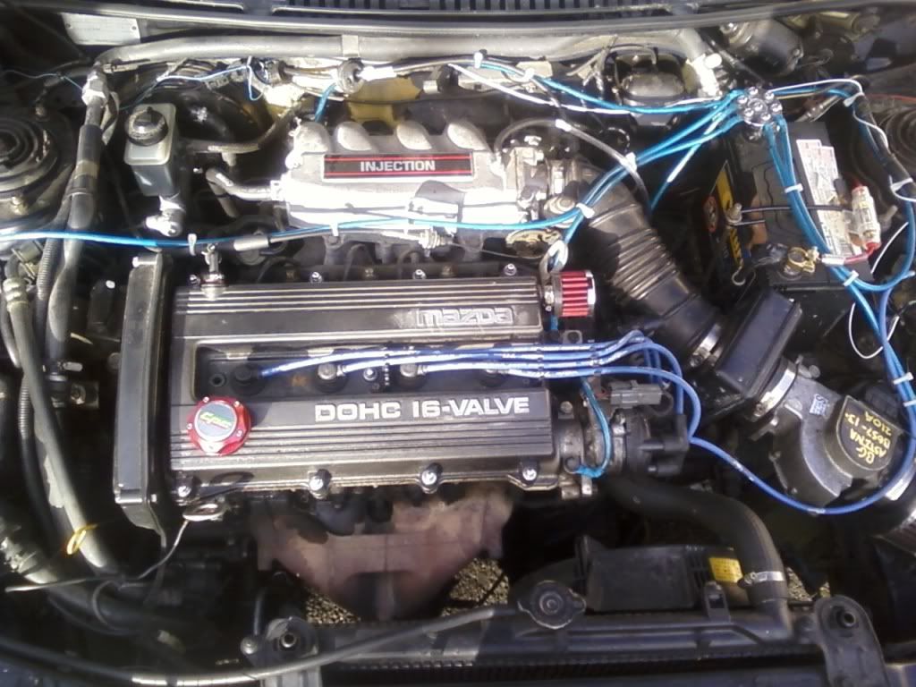
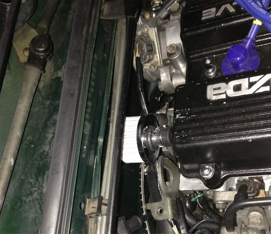
NA8 air intakes
Moderators: timk, Stu, zombie, Andrew, The American, Lokiel, -alex, miata, StanTheMan, greenMachine, ManiacLachy, Daffy
- droo
- Fast Driver
- Posts: 286
- Joined: Fri Apr 18, 2008 10:32 am
- Vehicle: NA8
- Location: The People's Republic of Bendigo
Re: NA8 air intakes
To be honest, i've no idea it's suitability for reading where it's reading but it's temp ratings state up to 127deg C for it's range of reading, so I figure as a component it should be able to reach close to that. Its also been on and in the car since october last year, 3 months in that environment, and during pretty extreme conditions - if it breaks, it's replaceable i figure, and have plenty spare! :-)
It does react to high temperature swings pretty fast. While likely not millitary grade, its enough for me to see general indications as well as specific readings when i want. Mentioned earlier I have boiled and iced the chips, I also remember having fun with one i was prepared to sacrifice (had a ceremony, chants and like.. everyfink...)
Not having used a thermocouple for extended use i couldn't compare it to it's reaction time but from zero degrees on ice, to having a 270 deg soldering iron touch it, took well less then 15 seconds to reach well over it's max reading. I didnt document this and i'm almost certain it was less then 7 sec in recounting the moment, but for arguments sake lets say memory is fallible.
Being boiled then pressed into ice had a similar swing downward ramp in temp. (tho i didnt actually time that)
The sensors on my setup are literally IN the air flow. The inlet temp sensor is literally in the middle of the entrance to the cowling air pipe.
The throttle body air temp sensor is in the airflow approx 2" out from the edge of the throttle's metal lip. (I'm not having anything close to the throttle incase it dislodges and blocks closure of the throttle.
Changes in air temp on the front grill driving at night from hill crests to valleys, where the valleys i've felt a LOT cooler then the crests (roof down) reflected with nearly 10 degree drops from my arduino reading. Driving through these results in changes within a few seconds. The grill temp sensor is cable tied to the actual grill of my car, which is not a mesh type grill like many others, but an actual amount of horizontal metal bars (dare i say... aston martinesque?) oh god, i just said it..
The sensors dont have heat sinks on them, the metal of the TO220 package is angled and exposed to the air path as best i could handle that- which wasnt difficult. Without the heatsinks the package is able to react much faster to instantaneous temp changes. - a heatsink attached would almost mechanically 'average' the instant variances which would be better off for a domestic thermostat in a corridor with random air breezes.
I do understand your thoughts on latent heat absorbtion can come into play, but as the sensors react within seconds to swings in temps, i'd hazard a guess (as best as i'm not an engineer) that it's able to refresh itself relatively well.
btw, i'd love to have a skype session and yack about this in person - it'd save my rants on here and my fingertips in typing!
- gslender
- Speed Racer
- Posts: 2330
- Joined: Sat Feb 19, 2011 10:49 pm
- Vehicle: NA6
- Location: Brisbane, QLD
Re: NA8 air intakes
Droo,
My suggestion is a simple test where you put the sensor in the direction of something that radiates heat (like a toaster or oven, iron). Ensure it heats up due to that. Then, apply a fan that is blowing colder air over the area. So that, in effect, the sensor is being radiated by heat (from the iron) but is also being cooled by air. Now the radiated heat needs be fairly large (like the real environment in the car) and the air needs to be smaller. You can't have a desk fan blowing over the sensor next to small pencil soldering iron - that wouldn't be a good test. But something like a hot exhaust manifold and then blowing a small amount of air from a tube would mimic the intake conditions. You need to consider that air moving through a tube isn't going to absorb a lot of heat from the tube... even though the tube could be 100*deg the air inside might be moving through it at 25*deg and not absorb much heat - mainly because the density of the air is so low.
There is a reason why intake air sensors are not TO-220 packages... they are often thin bits of wire (thermistors) that actually are thin enough and delicate to actually be effected by air temp, but shielded and protected from radiated heat. Only these types of devices correctly measure air temps.
I'm not trying to "rain on your parade" and actually commend your efforts, but I think you may not be scientifically getting the true results - I'm terribly keen though to work out how to help here... as being able to have an 8 sensor system that can work out the best intake temps and conditions would be awesome... and something I'm happy to help with.
G
MX5 91 NA6 LE completely stock and loving it!
MX5 92 NA8/ITBs Silver "aka Track Beeotch"
- droo
- Fast Driver
- Posts: 286
- Joined: Fri Apr 18, 2008 10:32 am
- Vehicle: NA8
- Location: The People's Republic of Bendigo
Re: NA8 air intakes
I hear you about the thermisters. The reason i use the TC74Ax chips was that they outputted an easy reading which wasnt influenced by other loads on the arduino. Other temp sensors i'd used were influenced by loads on other pins of the arduino and i simply wanted a 'more accurate' solution that didnt require much (or any) buffering electronics in between.
I'll setup a sensor in the situation you've outlined when i get home tonight.
- droo
- Fast Driver
- Posts: 286
- Joined: Fri Apr 18, 2008 10:32 am
- Vehicle: NA8
- Location: The People's Republic of Bendigo
Re: NA8 air intakes
as promised,
A TC74A7 chip, pre-heated to about 71 deg C sitting precariously on my engine and being heated by exhaust heat while the engine's idling.
the following pics are screen grabs from the video linked below.
intro:
The internal diameter of this hose is pretty much identical to a typical drinking straw, please keep that in mind the volume of air one can blow air through it.
I'm aiming the pipe at the non metal side of the sensor, which means the cooler air i'm blowing onto it should take a little longer to take effect. (but i dont know the internal structure of the chip itself and dont know where the silicon substrate is inside it) The exposed metal backing of this sensor is facing the exhaust heat.
With the first 3 seconds of me blowing air onto the sensor, the sensor's reading temperature drops 7 degrees (keep in mind this is still competing with the heat heat which is emanating from the heat shield's gap. It raises slowly when i stop from the heat escaping slowly from the shield's gap. (the flicker form 61 - 62- 61 represents an 0.5 degree variation which i've got the circuit ignoring decimal places.)
(please pardon the other half removed experiments on the board.. Theres no reason for me to work 'neatly' when i'm playing with this)
the full video straight off my phone (no tweaks) is here.
(1080p 91.2Mb iphone-mov format - right click and 'save as')
- gslender
- Speed Racer
- Posts: 2330
- Joined: Sat Feb 19, 2011 10:49 pm
- Vehicle: NA6
- Location: Brisbane, QLD
Re: NA8 air intakes
I think that's a problem then. What you'd want to see is the sensor drop to almost 30deg fairly quickly. The TO-22 package is absorbing too much heat if you can't blow it cool, as trust me, the air out of that tube isn't 60 deg!!
It's hard to say confidently as the reaction from the sensor is really good, but seeing it stall at 60 is a concern. Do you have a hair dryer that has a cool or non-heat mode?
End of the day you are probably close, but I'd be careful about what conclusions you form as the sensor package itself was never design to be used to measure intake air temps, so it's validity needs to be questioned in line with the conclusions you make.
G
MX5 91 NA6 LE completely stock and loving it!
MX5 92 NA8/ITBs Silver "aka Track Beeotch"
- droo
- Fast Driver
- Posts: 286
- Joined: Fri Apr 18, 2008 10:32 am
- Vehicle: NA8
- Location: The People's Republic of Bendigo
Re: NA8 air intakes
Your assumption is very right, the package takes a time to cool itself off - definitely not fast enough for what I think you are after and does heat up faster then it can shed heat, however it stopped at 60 deg c as i stopped blowing air on it at that point.
For me, being able to wipe off 50 degrees in about a minute (previous engine bay readings) is fine for my readings and a bit over a degree per second in an automotive environment is pretty quick.
Perhaps with an air compressor pushing a stronger flow (more inline with engine induction) these results may differ but i cant check for that as i dont have access to one.. Happy to repeat the test without having the heat source feeding the sensor from behind.
It definitely isnt designed for an air flow function and isnt able to swing it's reading as fast in free air versus contact with an object (tonight i've touched it with a soldering iron then touching ice against it) it adds or wipes off 30-50 degrees each second, but in free flowing air, not so fast, it will take about 30 seconds to adjust (and trying again tonight blowing cool air onto it was a little hampered by me getting headspins on the few tries i did (couldnt read the screen at the same time!) *sigh*
...aaaand i am definitely not forming conclusions for others, with the times between my previous results being in the order of minutes, i'd say that's somewhat enough to get a pretty good ball park figure - the actual degrees perhaps shouldnt be taken as canon, but the relative differences between them is what i was more keen on sharing. I want to put the numbers in for the sake of being more thorough :-) Validity - we need more people doing something similar on their cars! My sample size of one isn't anything to make a conclusion on! C'mon peeps!
i particularly chose to use this sensor as it plugs directly into me arduino, no extra electronics, and i wanted to keep it cheap and simple - check check!! )
(Also, sorry for venturing off topic with regard to air inlet setups)
-
- Racing Driver
- Posts: 1401
- Joined: Wed Nov 19, 2008 2:50 pm
- Vehicle: NA8
Re: NA8 air intakes
Hey droo,
All
Good. I think it's a great topic and thank you for all the info you have posted! Certainly has made me think and I'm sure plenty of others too!
At this stage I've decided to keep the current intake but I've reworked the bracket and refit and got a 63-75mm pipe and replaced afm. So much less restrictive than the afm!!
Got pics, will post this week.
Looking for an SVT motor for this:
viewtopic.php?f=73&t=62834
- droo
- Fast Driver
- Posts: 286
- Joined: Fri Apr 18, 2008 10:32 am
- Vehicle: NA8
- Location: The People's Republic of Bendigo
Re: NA8 air intakes
What are you using to meter/measure your air inplace of the AFM? are you a lucky bugger running a map sensor now? :-)
-
- Forum Guru
- Posts: 4897
- Joined: Mon Apr 24, 2006 7:27 pm
- Vehicle: NA8
- Location: Moruya, NSW
Re: NA8 air intakes
EW, just continuing on with your original line of thinking about trying something completely different ... how about using an Astina GT manifold?
It's the reverse of an MX5 one, meaning the throttle body would be at the back where it could, in theory, draw straight from the HVAC air collector box without any piping in the engine bay at all, except for a short length of flex. It would mean putting the MAF (for those who still had one) and a long thin air filter in the collector box. It would virtually eliminate any possibility of heat soak in the intake system.
Has anyone ever done it?
’95 NA8
-
- Racing Driver
- Posts: 1401
- Joined: Wed Nov 19, 2008 2:50 pm
- Vehicle: NA8
Re: NA8 air intakes
Hey Droo, yep - map sensor now with the Adaptronic.
So at this stage as mentioned Ive kept the current set up and put the pipe in the middle and refitted the bracket. quite a snug fit and doesnt move around anymore. the whole intake sits flush and flat. love it!
dont worry, I didnt use that pipe, used the better one, thats just a comparison to show how restrictive the AFM can be!
MG - thats a different way to look at it! although am I looking at it frm the right way thinking the brake booster/cylinder is?
Looking for an SVT motor for this:
viewtopic.php?f=73&t=62834
-
- Racing Driver
- Posts: 1720
- Joined: Wed Aug 03, 2011 5:57 pm
- Vehicle: NB SE
- Location: Sydney
Re: NA8 air intakes
So many issues with using the Astina inlet mani.
That pic is not the gt, no turbo! the turbo inlet mani is different, due to intercooler piping etc.
I just put an Astina engine into my MX5, and contemplated using the astina manifold.
The FWD astinas, B6 or BP, use the 1.6 throttle body! so if you have an NA8 mx5, it would have the VTPS and the ecu would need that input to run. You would have to make sure the Astina manifold had a throttle body with VTPS on it, and that it is the same plug for your mx5 loom.
the throttle body inlet basically lines up with the breather tube off the rocker cover.
Here is my MX5 with that same rocker cover and breather. About 3mm clearance from fire wall...
So to fit the Astina mani/throttle body in, you would have to
1) re-route A/C lines
2) move clutch master cylinder
3) move the riveted vin number plate
4) re-route break lines
5) re-route clutch lines
6) the throttle wheel would be completely backwards...
Really not possible
Good idea though!
Also, the Astina mani weighs about 10kg!!!! it is soooo heavy compared to the alloy mx5 one.
-
- Racing Driver
- Posts: 1401
- Joined: Wed Nov 19, 2008 2:50 pm
- Vehicle: NA8
Re: NA8 air intakes
yeah I'll pass haha too much effort for me!
Looking for an SVT motor for this:
viewtopic.php?f=73&t=62834
-
- Forum Guru
- Posts: 4897
- Joined: Mon Apr 24, 2006 7:27 pm
- Vehicle: NA8
- Location: Moruya, NSW
Re: NA8 air intakes
Thanks Emily. I thought it was a great idea too! Imagine the joy of no intake piping whatsoever in the engine bay.
Bit of a buggar about the clutch cylinder though. I have an BG Astina with the SOHC BP sitting next to my car. I'd worked out the issues with the VIN plate, the brake lines, the A/C lines and the throttle cable, They weren't really biggies but without a proper DOHC manifold I couldn't be sure about the clutch cylinder. Obviously relocating the master cylinder itself was never going to be a goer but it looked like there was a chance of getting away with just relocating the clutch fluid reservoir. Just depended on thew shape of the DOHC manifold at that end.
’95 NA8
-
- Speed Racer
- Posts: 11854
- Joined: Mon Aug 08, 2005 11:35 pm
- Vehicle: Clubman
- Location: Melbourne
Re: NA8 air intakes
manga_blue wrote:...how about using an Astina GT manifold?
Would be interesting if it could be done, & Emily or Project.r.racing could confirm or refute, but think you'll find the MX5 BP makes some power over the Astina BP through using the MX5 BP manifold.
-
- Racing Driver
- Posts: 1401
- Joined: Wed Nov 19, 2008 2:50 pm
- Vehicle: NA8
Re: NA8 air intakes
Silly question regarding me removing the afm, it was obviously tuned without it, but was sitting there in the intake. Would I 'need' to get it back on the dyno to see if any changes just to be safe?
Looking for an SVT motor for this:
viewtopic.php?f=73&t=62834
Return to “MX5 Engines, Transmission & Final Drive”
Who is online
Users browsing this forum: No registered users and 69 guests