Turbo Install - Idle intake & Gauges

Discussion regarding Turbocharged and supercharged MX-5s

Moderators: timk, Stu, zombie, The American, Lokiel, -alex, StanTheMan, greenMachine, ManiacLachy, Daffy, Sean

User avatar
CapitalF
Fast Driver
Posts: 245
Joined: Tue Jun 05, 2007 10:35 am
Vehicle: NA6 - Turbo
Location: Gold Coast

Turbo Install - Idle intake & Gauges

Postby CapitalF » Tue Apr 21, 2009 10:57 am

Hi

Just installing turbo with integrated wastegate on NA6 with IC, big injectors / extra fuel pump and Megasquirt / EBC / Wideband O2 sensor / IAT ie. running no AFM / new 2.5 exhaust. For a track day / weekend warrior vehicle. No A/C anymore.

1. Is the idle intake hose best to be plumbed:

a) back into the intake pre turbo, post filter / pod
b) to just have a small filter on it so independent (easiest by far)
c) to be taking boosted/cooled air post IC / pre throttle body?

and why?


2. Also - any strong recommendations for gauges setup? I have a panel where the radio normally sits and will prob put water temp and oil pressure there so I can check if the ECU shows me signs of reaching set levels of protection.


Should be tuned and ready for some "higher load testing" by QLD MX5 Club trackday at Lakeside. 8)


Thx all
Peter
90 Silver Roadster 1.6 + GT2554, large IC, MS-PNP, lightened flywheel, HD Clutch, 2.5" exh, Teins, Whiteline, etc etc

User avatar
Boags
Speed Racer
Posts: 3533
Joined: Thu Nov 10, 2005 6:25 pm
Vehicle: NB SP
Location: Brisvegas
Contact:

Turbo Install - Idle intake & Gauges

Postby Boags » Tue Apr 21, 2009 11:04 am

Hi Peter,

All regarding Q1:

Definitely option (a). Option (c) will lead to a pressurised cam case and problems associated. Option (b) *may* get you in trouble if the plod ever look under the bonnet. Technically you couldn't get the turbo kit engineered if you took that option.

Guages need to be where you can keep an eye on them. I had my a/f guage in the 3rd DIN pocket and could keep and eye on it most times. It would have been a bit better if it was higher.

Cheers,
Boags
Spartan Motor Sport : http://www.SpartanMS.com.au

User avatar
GS
Fast Driver
Posts: 260
Joined: Mon May 15, 2006 6:40 pm
Vehicle: NA6
Location: Sydney

Turbo Install - Idle intake & Gauges

Postby GS » Tue Apr 21, 2009 12:08 pm

Are you talking about the idle air bypass (the short pipe that runs from just before the TB to the idle controller under the intake manifold) or the blow through pipe (long pipe which runs from before the TB across the engine to the right side of the cam cover)?

Idle controller = option C
Blow through = as per Boags answer
Image
1989 NA6

User avatar
CapitalF
Fast Driver
Posts: 245
Joined: Tue Jun 05, 2007 10:35 am
Vehicle: NA6 - Turbo
Location: Gold Coast

Turbo Install - Idle intake & Gauges

Postby CapitalF » Tue Apr 21, 2009 12:52 pm

Thx guys,

Yes it is the Idle Air controller and will go Option a.

Re gauges - I think I'll just get a water temp with integrated preset temp warning light mounted up high and a shift/warning light to go on the steering wheel or top of dash. The ECU settings will protect me (to a degree) from doing real damage and I don't think on the track you spend much if any time looking at these things except when you have a problem. I cant cope with buzzers.

Thx
Peter
90 Silver Roadster 1.6 + GT2554, large IC, MS-PNP, lightened flywheel, HD Clutch, 2.5" exh, Teins, Whiteline, etc etc

User avatar
Garry
Speed Racer
Posts: 3481
Joined: Sun Apr 27, 2003 11:00 am
Vehicle: NB SP
Location: God's Country
Contact:

Turbo Install - Idle intake & Gauges

Postby Garry » Tue Apr 21, 2009 3:31 pm

If you are still using an air flow meter of some type it needs to be after the AFM. The factory location is just before the throttle body in every MX5 I've looked at and also on the SP.
Shiney black one with added red bits. Member of the fart club. Now with extra doof and Sunlong. - deceased and gone to heaven

Fatty
Speed Racer
Posts: 3175
Joined: Fri Feb 03, 2006 10:39 am
Vehicle: NA6
Location: Melbourne

Turbo Install - Idle intake & Gauges

Postby Fatty » Tue Apr 21, 2009 4:27 pm

my na6 had it plumbed into the inlet pipe in the stock location, using the oem pipe. why would you bother putting it somewhere else?

User avatar
CapitalF
Fast Driver
Posts: 245
Joined: Tue Jun 05, 2007 10:35 am
Vehicle: NA6 - Turbo
Location: Gold Coast

Turbo Install - Idle intake & Gauges

Postby CapitalF » Tue Apr 21, 2009 4:53 pm

Fatty wrote:my na6 had it plumbed into the inlet pipe in the stock location, using the oem pipe. why would you bother putting it somewhere else?


I used to have the plastic inlet pipe coming from the AFM across to the throttle body and this 10cm long question mark shaped hose (just below the throttle body) plugged into that OEM plastic pipe. I no longer have that as I've removed the AFM and pipe, now having an inlet pipe coming up from the added Intercooler to throttle body. As I half thought before posting, this hose needs to now connect back to the air intake post filter, pre turbo as per Boags reasoning above.

Peter
90 Silver Roadster 1.6 + GT2554, large IC, MS-PNP, lightened flywheel, HD Clutch, 2.5" exh, Teins, Whiteline, etc etc

Fatty
Speed Racer
Posts: 3175
Joined: Fri Feb 03, 2006 10:39 am
Vehicle: NA6
Location: Melbourne

Turbo Install - Idle intake & Gauges

Postby Fatty » Tue Apr 21, 2009 4:57 pm

sorry my post was not very clear. i'll put a photo up for you tonight, easier that way.

User avatar
GS
Fast Driver
Posts: 260
Joined: Mon May 15, 2006 6:40 pm
Vehicle: NA6
Location: Sydney

Turbo Install - Idle intake & Gauges

Postby GS » Tue Apr 21, 2009 6:23 pm

I think we're talking at cross purposes here.

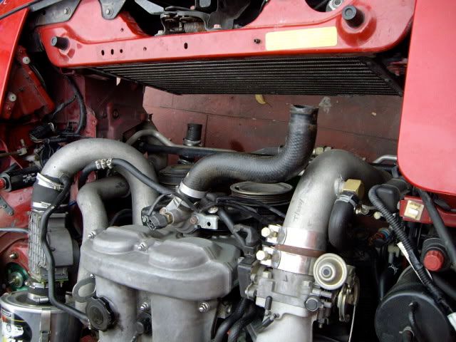
Boags is talking about the blow through pipe that exits the right hand side of the cam cover. On the stock set up it exits the cam cover as a rubber tube, connects to a thin metal pipe that runs across the front of the engine, then continues as another rubber section into the inlet pipe before the throttle body. When you install a turbo, this pipe needs to be replaced by either a short tube from the cam cover to the post AFM/pre-turbo intake tube, or into a catch can/filter. If not, the cams get pressurised post turbo air.

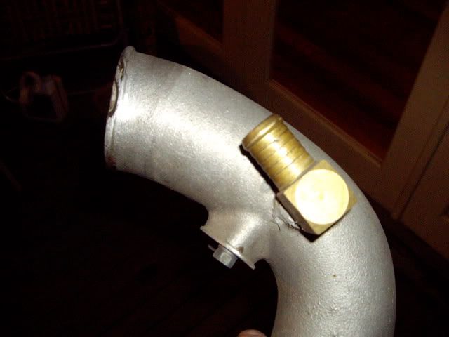
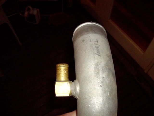
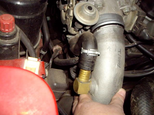
However, the idle controller is a rubber pipe runs from the inlet pipe (just before the throttle body) to the idle controller unit below the inlet manifold. This is a fatter rubber pipe, and sounds like the question mark tube you're describing. Once you install the turbo you still need this pipe to feed from the stock location in the inlet pipe. I think this is what fatty was thinking of when he said "why would you use any other location?".

I'll try to find a pic to explain.
Image
1989 NA6

User avatar
GS
Fast Driver
Posts: 260
Joined: Mon May 15, 2006 6:40 pm
Vehicle: NA6
Location: Sydney

Turbo Install - Idle intake & Gauges

Postby GS » Tue Apr 21, 2009 6:32 pm

This might make it clearer.

The pipe labelled "0.5 coupler brazed" is the idle control pipe. Your intercooler to throttle body pipe should include an outlet to attach this pipe (as this guy has fabricated on his intercooler pipe).

Image

In the centre of this pic you can see the black rubber S shaped blow through pipe. This guy has diverted it from his cam cover to a spot pre-turbo/post-AFM.

Image

Hope it makes more sense.
Image
1989 NA6

Fatty
Speed Racer
Posts: 3175
Joined: Fri Feb 03, 2006 10:39 am
Vehicle: NA6
Location: Melbourne

Turbo Install - Idle intake & Gauges

Postby Fatty » Tue Apr 21, 2009 7:34 pm

GS wrote:I think we're talking at cross purposes here.


agreed, and agreed with your pics. here is my version

Image
Image
Image
Image

User avatar
CapitalF
Fast Driver
Posts: 245
Joined: Tue Jun 05, 2007 10:35 am
Vehicle: NA6 - Turbo
Location: Gold Coast

Turbo Install - Idle intake & Gauges

Postby CapitalF » Tue Apr 21, 2009 9:47 pm

Oh - I should have used pictures straight up guys!

Sorry - I did misunderstand Boags, thinking he was referring to the idle controller, rather than the blow through pipe. I knew the pipe on the passenger side of cam cover (blow thru pipe) needed to go to catch can or post Filter/pre turbo. In my case will go to catch can as it's far from being a daily driver.

I was always talking about the idle controller, adjacent to the throttle body, and can see from the pics it does go from the original position (engine end) into the IC>throttle body. So, the answer from my original post is actually c).

I'll have to read further some day so I understand why that works entirely.

Thx v much all. Much appreciated input as usual.

Peter
90 Silver Roadster 1.6 + GT2554, large IC, MS-PNP, lightened flywheel, HD Clutch, 2.5" exh, Teins, Whiteline, etc etc

User avatar
Garry
Speed Racer
Posts: 3481
Joined: Sun Apr 27, 2003 11:00 am
Vehicle: NB SP
Location: God's Country
Contact:

Turbo Install - Idle intake & Gauges

Postby Garry » Wed Apr 22, 2009 8:44 am

In the later cars Mazda got a bit neater and did it internally inside the throttle body doing away with the rubber pipe.
Shiney black one with added red bits. Member of the fart club. Now with extra doof and Sunlong. - deceased and gone to heaven

User avatar
Boags
Speed Racer
Posts: 3533
Joined: Thu Nov 10, 2005 6:25 pm
Vehicle: NB SP
Location: Brisvegas
Contact:

Turbo Install - Idle intake & Gauges

Postby Boags » Wed Apr 22, 2009 11:35 am

Yes, my mistake. I had my wires crossed. Some very good pics there for those planning an install...
Spartan Motor Sport : http://www.SpartanMS.com.au

buz 138
Driver
Posts: 53
Joined: Wed Jun 03, 2009 9:25 pm
Vehicle: ND - 2
Location: northern burbs of melbourne.

Turbo Install - Idle intake & Gauges

Postby buz 138 » Fri Jun 05, 2009 7:09 pm

hi guys,
sorry to hijack thread..
..but does anyone see a problem with using i 'T' piece instead of the elbow in the above pics and installing a BOV from here also? (so the idle intake is coming off one side and the BOV on the opposite)


Return to “MX5 Forced induction (Turbo/Supercharger)”

Who is online

Users browsing this forum: No registered users and 3 guests