so i've been doing a lot of research and reading and i'm a bit overwhelmed by it all i must say.
so anyway, been looking into this MAP sensor business and came across this quote :
\"An engine control system that uses manifold absolute pressure to calculate air mass, is using the speed-density method. Engine speed (RPM) and air temperature are also necessary to complete the speed-density calculation.\"
so, getting the rpm is easy. there is already a sensor for that. but how do you measure the air temperature? are you using a pre-existing sensor that i don't know about, or just using some guesstimate number that is used in the calculation, a \"near enough is good enough\" sort of approach ? ?
question for people using MAP sensors
Moderators: timk, Stu, -alex, miata, StanTheMan, greenMachine, ManiacLachy, Daffy, zombie, Andrew, The American, Lokiel
-
Fatty
- Speed Racer
- Posts: 3175
- Joined: Fri Feb 03, 2006 10:39 am
- Vehicle: NA6
- Location: Melbourne
-
Fatty
- Speed Racer
- Posts: 3175
- Joined: Fri Feb 03, 2006 10:39 am
- Vehicle: NA6
- Location: Melbourne
thanks for the detailed reply steve. i appreciate it.
as to your question as to why i am looking at going this route with the stock ecu. well, the answer is that i want to retain the stock ecu as i don't want to spend too much cash. i just want the best result i can get with the stock ecu. if that means that i'm stuck with the stock afm (or a suitable alternative such as the rx7 afm) , then so be it. but if it is possible to somehow figure out a way to use a map or tmap sensor, then that would be grand. i know that the general consensus of the forum whenever these sorts of questions are asked is \"just get a new ecu\". but i plan on doing the best i can with the stock one.
so i have a sensor in my mind and i just need to know if such a thing exists. it is a tmap sensor. it reads air temperature and map, and outputs a voltage that roughly corresponds to the voltage outputs on the stock afm. so it would read somewhere roughly around 3 - 4V at idle and roughly 1V at full load. does such a sensor exist? probably not. but if it does, welll hey i might be in business, because as long as the voltage is roughly in the ballpark of the afm voltage, i can modify it with my dfa before it gets to the ecu.
i'm probably asking too much but i figure this is what forums like this are all about, to share ideas and knowledge.
-
Fatty
- Speed Racer
- Posts: 3175
- Joined: Fri Feb 03, 2006 10:39 am
- Vehicle: NA6
- Location: Melbourne
-
Fatty
- Speed Racer
- Posts: 3175
- Joined: Fri Feb 03, 2006 10:39 am
- Vehicle: NA6
- Location: Melbourne
thanks steve. i really appreciate that.
yes i seriously considerred going down the megasquirt path. but i decided that , although it would give me a lot more tuning power, that the added headache of tuning basically every parameter from scratch would be more trouble than it was worth. from reading the results of people who use the megasquirt, they report great results but it seems that it takes a lot of time and effort to sort out cold starts etc. seems like a headache i don't need.
i'm thinking that the stock ecu is matched to the engine, has all those fiddly issues sorted out already, it just needs a little bit of tweaking the air/fuel ratio (and maybe timing but i'll worry about that later) to get a really nice result. plus, the DFA was less than half the price of the megasquirt
so as i'm keen to keep it as simple as possible, i think the MAP sensor idea is out of the question. but i was just thinking out loud, so to speak. i will stick with the afm. i'm only after a nice little increase in power, i'm not trying to build a monster here.
-
Fatty
- Speed Racer
- Posts: 3175
- Joined: Fri Feb 03, 2006 10:39 am
- Vehicle: NA6
- Location: Melbourne
oh really? wish i knew that a few days ago before i bought my DFA 
i will certainly remember that tho, if i ever decide to get a bit more serious and go down the replacement ecu path. thanks steve!
so does the megasquirt allow you to vary the timing? for example, a common mod is to advance it to 14 degrees for more torque down low. but then the engine doesn't run as nice up in the higher rev range (so i believe). so if you could advance the timing then at a fixed point revert back to normal timing, well that would be sweet.
-
Fatty
- Speed Racer
- Posts: 3175
- Joined: Fri Feb 03, 2006 10:39 am
- Vehicle: NA6
- Location: Melbourne
cool, that sounds great steve.
ok i think i MIGHT be able to accomplish something similar for another $79 if i can figure out what sort of signal the crank angle sensor is sending to the ecu. there is another kit , a digital pulse adjuster (DPA), that is controlled by the same hand controller that i bought for my DFA.
i just need to know if the CAS sends a pulse , duty cycle or whatever , and whether this can be modified in such a way to control the timing. this would give me pretty much all the control i need. i know it doesn't give me the same monitoring power as the megasquirt softwars does, but i've started down this jaycar road and i'm interested to see how far i can take it ( on the proviso that it doesn't end up costing more $$ than a megasquirt).
-
Fatty
- Speed Racer
- Posts: 3175
- Joined: Fri Feb 03, 2006 10:39 am
- Vehicle: NA6
- Location: Melbourne
hey steve i owe you a sixpack or something.
so if i am interpreting this correctly, the CAS is sending 2 duty cycle signals or pulse signals to the ecu, known as the CKP and CMP signal.
the CMP signal is fixed. the timing of the CKP signal can be varied by moving the CAS, as is commonly done in the \"advance to 14 degrees\" mod.
i am assuming that the ECU just compares the timing of the two signals to decide where the CAS is set.
now, (bear with me here ) if it is possible to somehow delay the CKP signal by a few milliseconds( or whatever time is needed) , you could fool the ECU into thinking that the CAS is set to, say, 10 degrees, when in reality it is set at 14 degrees.
there is a $35 jaycar module that uses \"pulse outputs to switch a relay. The switch frequency can be set to trip when it is rising or falling \". the relay loop could then have a device in it that delays the CKP signal the desired amount (if such a device exists )
)
i just need to clarify in my head whether the signal that CKP is sending is a pulse signal or a duty cycle, or indeed whether these 2 terms mean the same thing. i don't have my head around that properly yet.
then i need to figure out some way to delay it by the required amount.
or am i getting WAY to technical again, like i did with the MAP sensor idea
so if i am interpreting this correctly, the CAS is sending 2 duty cycle signals or pulse signals to the ecu, known as the CKP and CMP signal.
the CMP signal is fixed. the timing of the CKP signal can be varied by moving the CAS, as is commonly done in the \"advance to 14 degrees\" mod.
i am assuming that the ECU just compares the timing of the two signals to decide where the CAS is set.
now, (bear with me here
there is a $35 jaycar module that uses \"pulse outputs to switch a relay. The switch frequency can be set to trip when it is rising or falling \". the relay loop could then have a device in it that delays the CKP signal the desired amount (if such a device exists
i just need to clarify in my head whether the signal that CKP is sending is a pulse signal or a duty cycle, or indeed whether these 2 terms mean the same thing. i don't have my head around that properly yet.
then i need to figure out some way to delay it by the required amount.
or am i getting WAY to technical again, like i did with the MAP sensor idea
-
Fatty
- Speed Racer
- Posts: 3175
- Joined: Fri Feb 03, 2006 10:39 am
- Vehicle: NA6
- Location: Melbourne
-
Fatty
- Speed Racer
- Posts: 3175
- Joined: Fri Feb 03, 2006 10:39 am
- Vehicle: NA6
- Location: Melbourne
yeah that sounds like a duty cycle to me steve. have a look at this diagram to see, which shows what the signal looks like when it goes from 5V to ground.
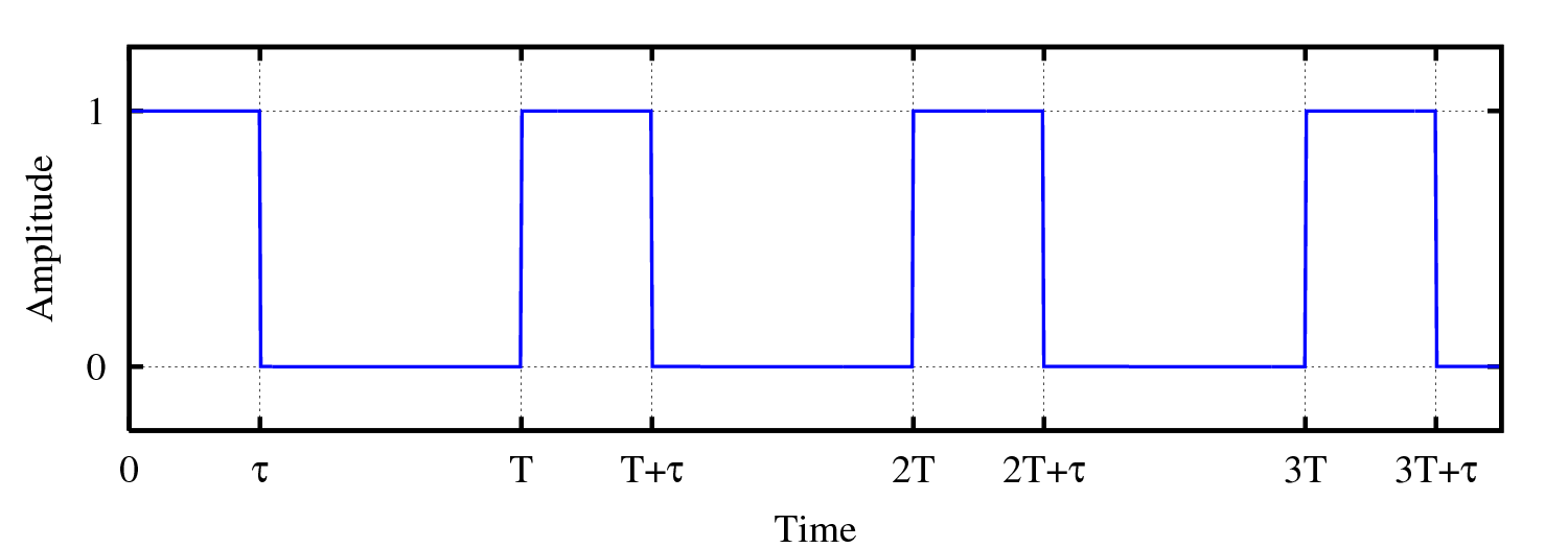
the term duty cycle refers to the relationship between the pulse duration and the pulse period.
now, i am hoping that the placement of the CAS does not affect the shape of the duty cycle at all. i'm hoping that by advancing the timing it just brings the pulses of the CKP signal forward in time in comparison to the CMP signal, or by retarding the timing it moves the signal back in time in comparison to the CMP signal.
coz if it's as simple as that, well then it shouldn't be too hard achieve some sort of fixed switchable delay of the signal, which will result in variable timing at a pre-set rpm.
but i'll need to get my oscilloscope out and have a look at the signal, while manually altering the timing setting. advance it and retard it and see what happens. i'll need a timing light etc. anyway this is all very interesting in theory, it'll take a bit of mucking around with.
-
Matty

- Racing Driver
- Posts: 1652
- Joined: Wed Apr 23, 2003 11:00 am
- Vehicle: NB8A
- Location: Melbourne
- Contact:
The \"duty cycle\" of the pulses off the CAS are purely a function of the size of the slots in the disk. You can't alter them and that wouldn't do anything anyway...
You could use a Bipes ACU interceptor to retard timing at high revs. Then advance the timing by rotating the CAS, and you'll have advanced low speed timing and normal high speed timing... A few people in the US use this. (there's a good thread on the big forum about overclocking the ECU and doing this with good results)
You could use a Bipes ACU interceptor to retard timing at high revs. Then advance the timing by rotating the CAS, and you'll have advanced low speed timing and normal high speed timing... A few people in the US use this. (there's a good thread on the big forum about overclocking the ECU and doing this with good results)
-
Fatty
- Speed Racer
- Posts: 3175
- Joined: Fri Feb 03, 2006 10:39 am
- Vehicle: NA6
- Location: Melbourne
-
Fatty
- Speed Racer
- Posts: 3175
- Joined: Fri Feb 03, 2006 10:39 am
- Vehicle: NA6
- Location: Melbourne
-
Fatty
- Speed Racer
- Posts: 3175
- Joined: Fri Feb 03, 2006 10:39 am
- Vehicle: NA6
- Location: Melbourne
ok i found the bipes website. that is a cool unit, it's a lot more complex than what i'm talking about as it uses airflow and air temp, as well as rpm, to decice how much retard to apply and when to apply it. it is not just a fixed retard at a set rpm like i'm talking about. it's also $370. i could build a megasquirt for less than that!
but what it has confirmed is that i am on the right track. i think i can nut something out for a lot less than $370!
but what it has confirmed is that i am on the right track. i think i can nut something out for a lot less than $370!
-
The Pupat
- Fast Driver
- Posts: 350
- Joined: Mon Mar 01, 2004 10:21 pm
- Vehicle: ND - 2 GT
- Location: Brisbane
Re: the CAS Signal PWM?
That is a digital pulse signal not a Pulse Width Modulated signal.
Pulse width modulation (this is where the term duty cycle is most commonly used) is used to control electronic items like electric motors and fuel injection solenoids without the need for a Digital to Analog converter.
What you have there is just a digital pulse signal which the computer would be acting on either the rising end (it acts on the 0 -> 1 transition) or the trailing edge (1 -> 0 transition) to activate sections of code in the ECU.
I'm actually worried that you have an oscilloscope yet clearly don't understand how this works.
When you shift the CAS it will shift both the RPM and the TDC signals either forwards or backwards in relation to the real TDC (IE you'll be phasing the signals out from each other). It does not matter to the computer if you move the RPM signal since it would eb calculating the RPM based upon how often it is receiving those rising or trailing edge signals. Moving the TDC signal will affect the motor because that signal tells the ECU when to start the firing sequence for the spark (IE It would work off a delay from when it recieved the previous signal to tell it when to fire the next spark (since you usually fire spark before TDC you would have to work this way).
Anyway I'm fairly certain there is no downpoints in advanced timing in the upper rev range, it's just the that gains seen at lower revs become significantly less in the upper rev range due to the speed everything is happening.
'92, Red, Hardtop, Noisy CAI, Even more Noisy Exhaust, AVO Shocks with TJR Springs (Not so Fuli drifto speco).
Return to “MX5 Engines, Transmission & Final Drive”
Who is online
Users browsing this forum: No registered users and 3 guests


