NC 20BPP Time Attack / Track Car - Build Thread
Moderators: timk, Stu, -alex, miata, StanTheMan, greenMachine, ManiacLachy, Daffy, zombie, Andrew, The American, Lokiel
-
Eeyore

- Driver
- Posts: 88
- Joined: Tue Apr 09, 2013 8:26 pm
- Vehicle: Clubman
- Location: Ipswich, QLD
Re: NC Track Car - In the Build
Had a quick look at the beast today. It's fantastic to see the amount of work the whole team has put in. There is a lot more cool fabrication to come too! 
Kurt
1971 1300 Estate Deluxe
1973 1300 Wagon
1979 RX7
1971 1300 Estate Deluxe
1973 1300 Wagon
1979 RX7
-
orx626

- Forum sponsor
- Posts: 1774
- Joined: Thu Sep 23, 2004 8:26 am
- Vehicle: NC - Rotary
- Location: Brisbane - Northside
- Contact:
Re: NC Track Car - In the Build
There's been some good progress in design, manufacturing and assembly over the past week or so.
Starting with design...most effort has been put into the heat exchanger assembly which integrates with the front splitter/diffuser. I don't think I've put up up photos of the engine coolant radiator and engine oil cooler. So here they are.
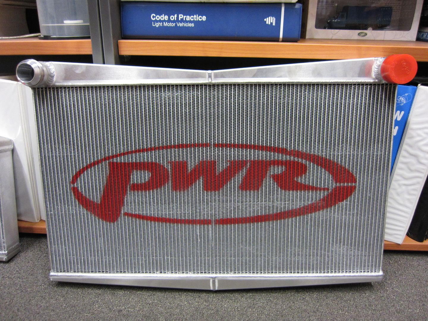
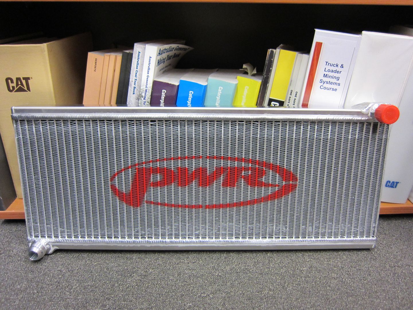
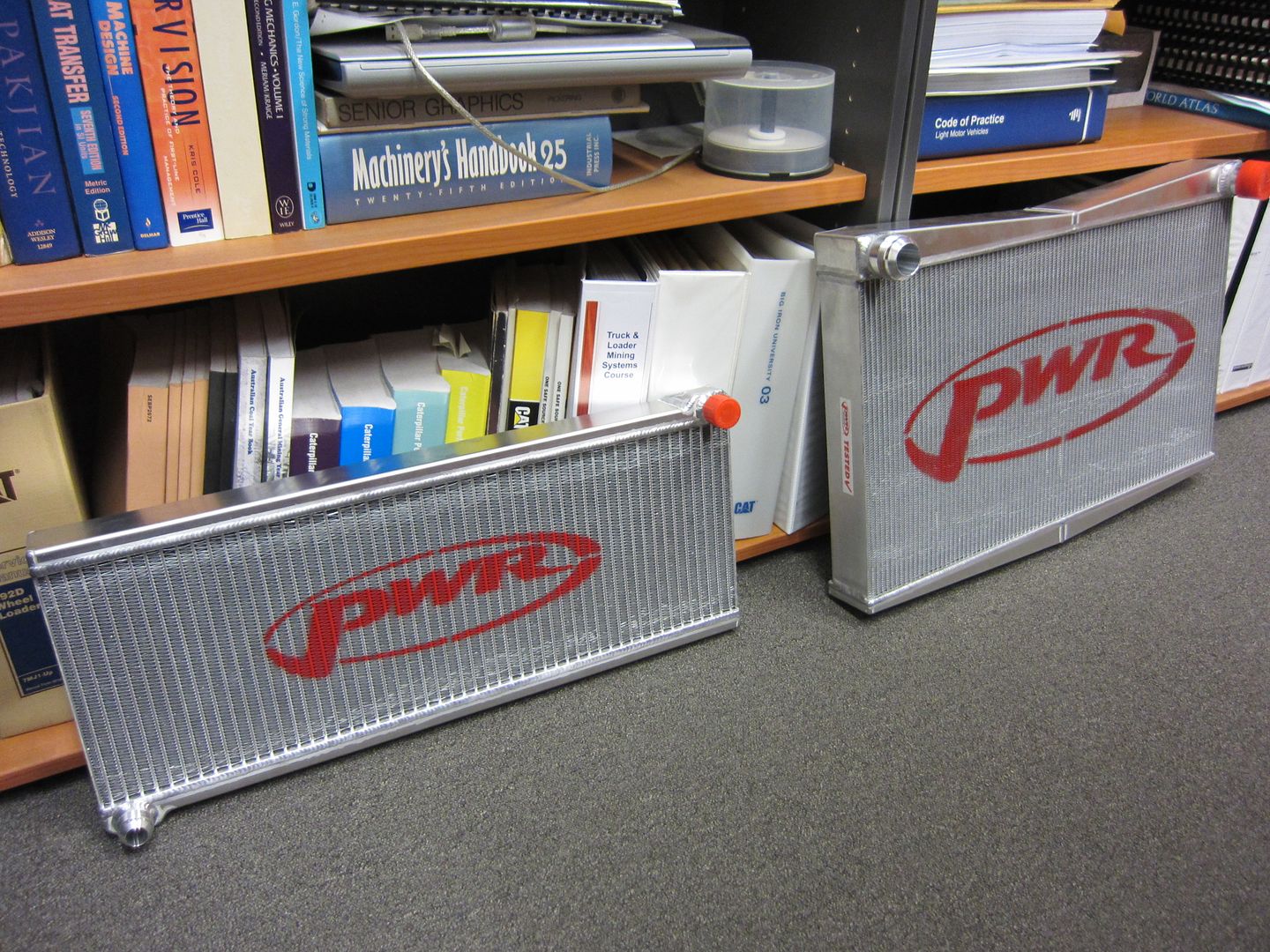
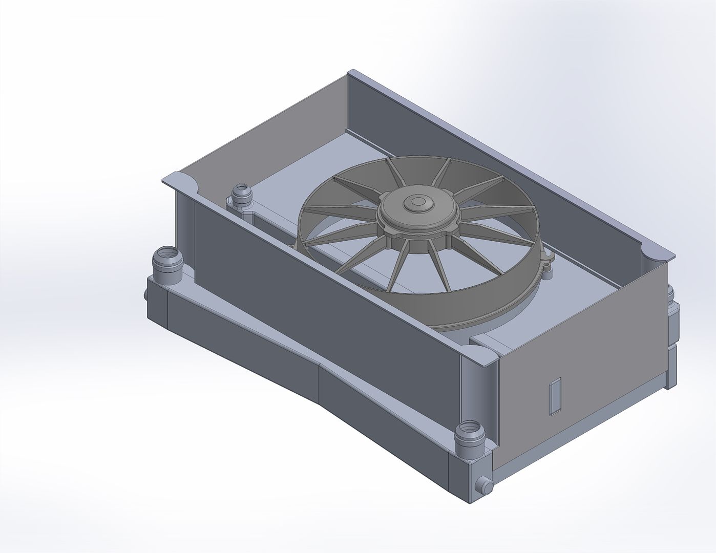
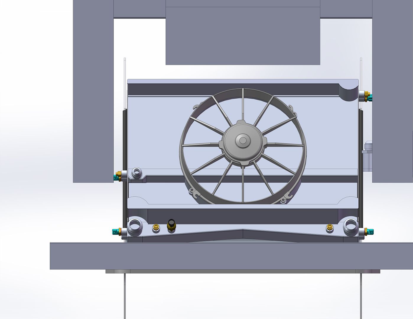
So basically the concept is that the two heat exchangers are welded together to form an air tight box that is part of the ducted cooling air system. A Spal thermo-fan is also included to provide air flow whilst the vehicle is stationary or has low road speed.
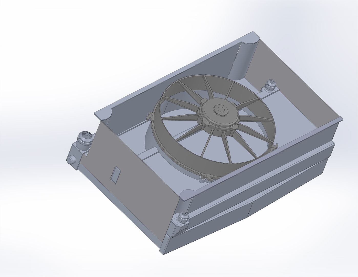
Materials for the above and the rest of the ducted air system (below) should be ordered this week.
Manufacturing wise, the following has been completed.
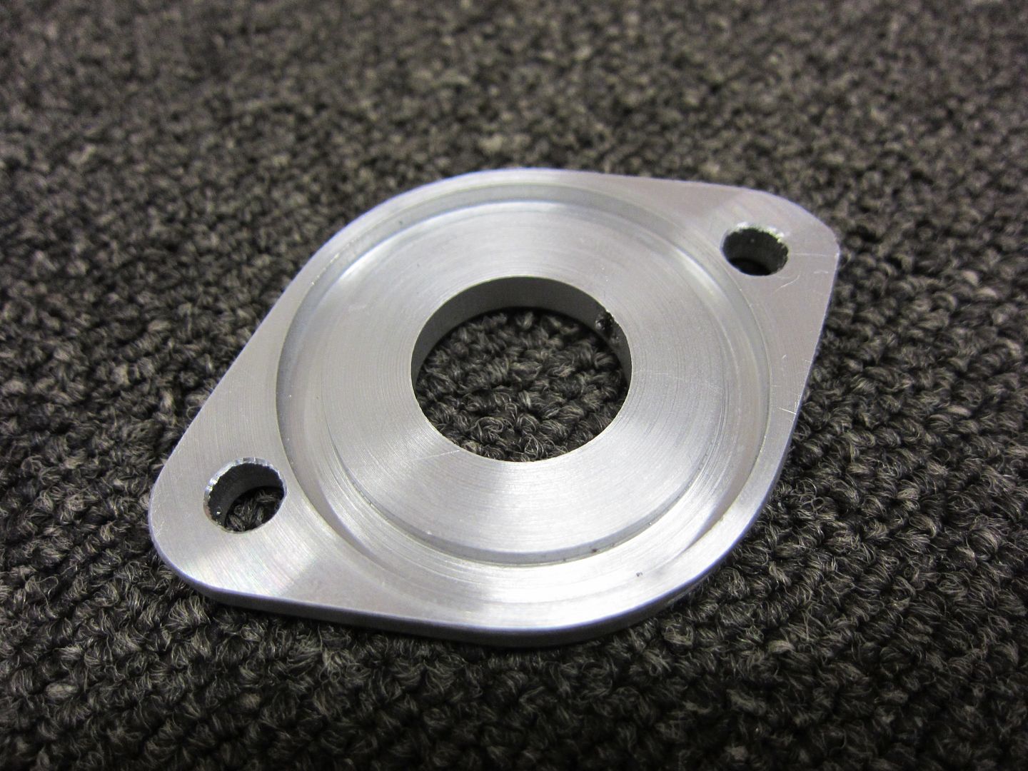
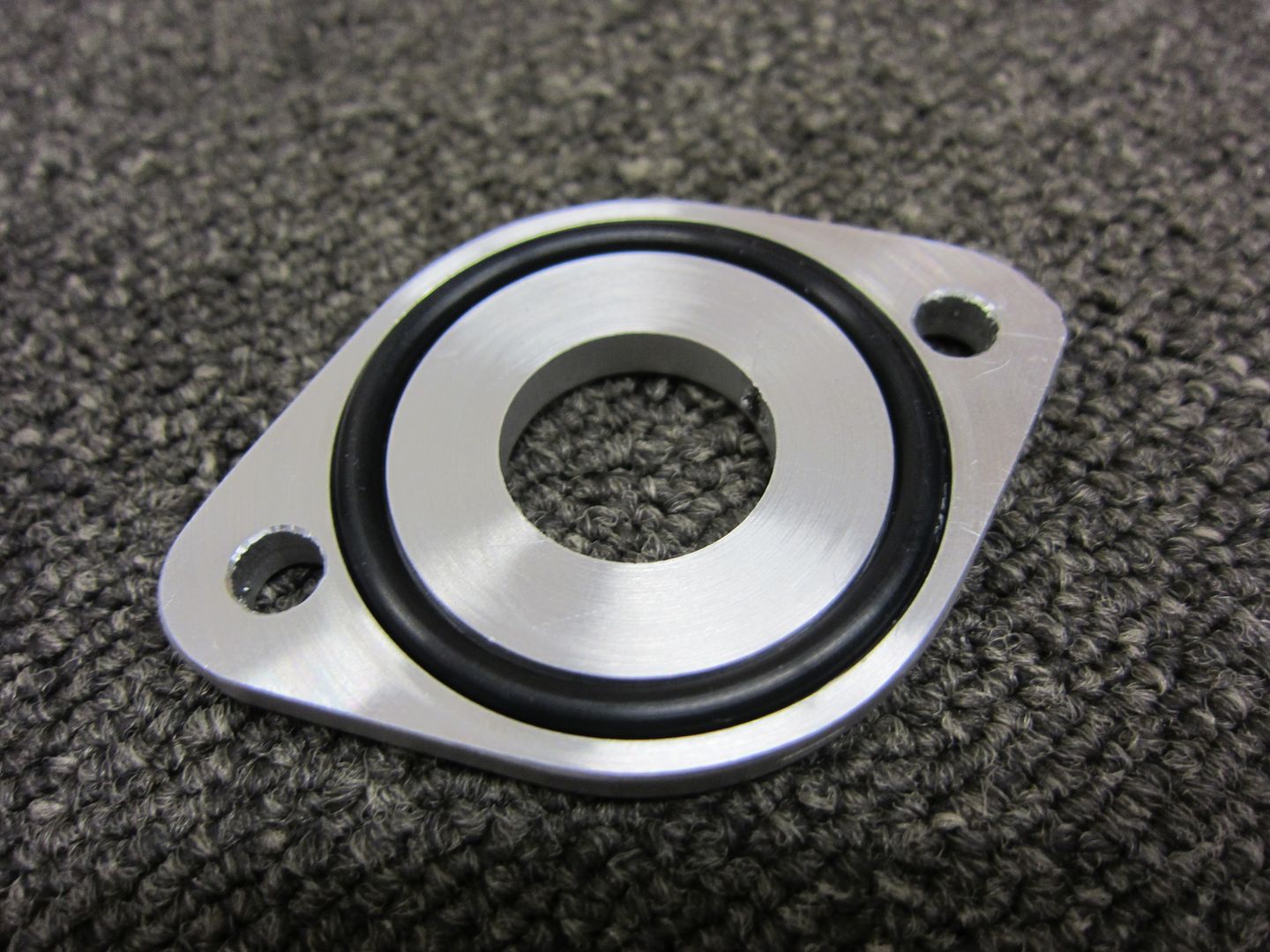
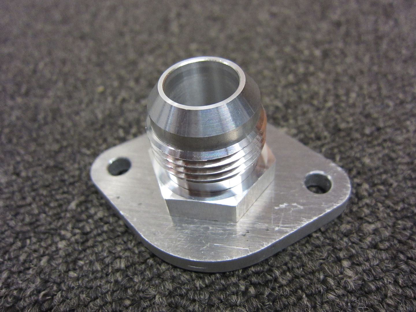
Adaptor flange for the crankcase breather line on the intermediate plate (previously the oil filler neck).
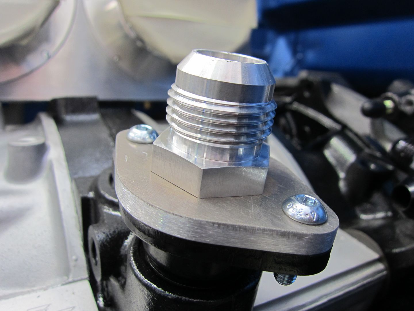
...and installed.
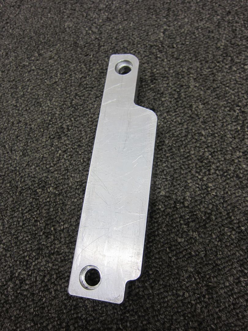
The adaptor to mount the RX-8 starter motor. Just needs to be drilled and tapped with a bell housing bolt thread once measured.
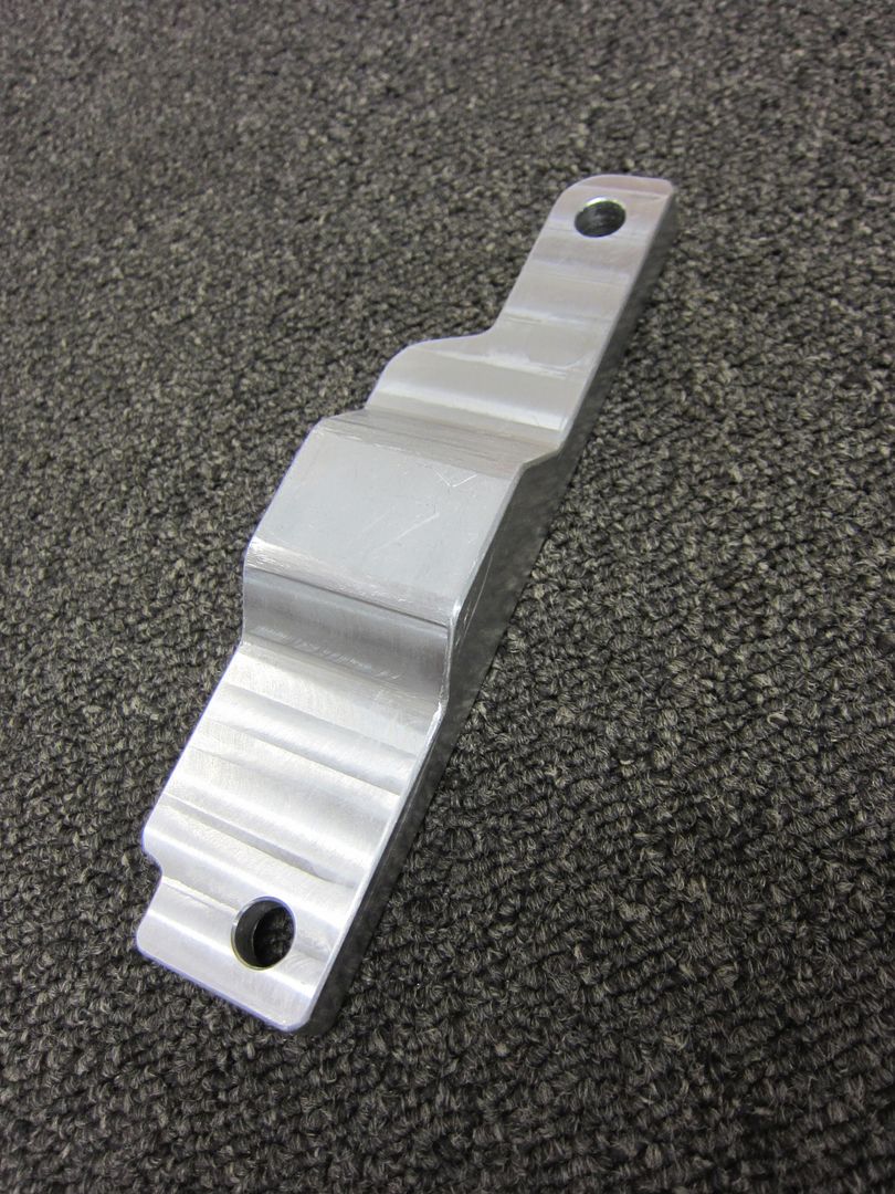
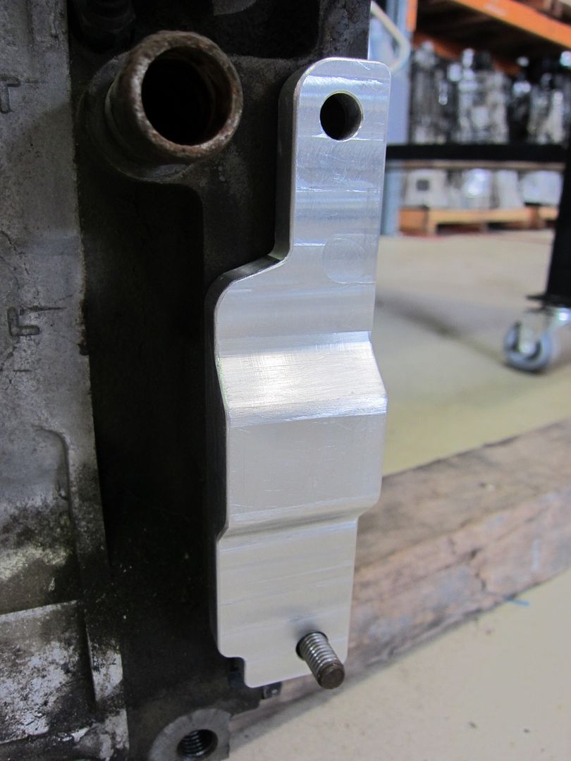
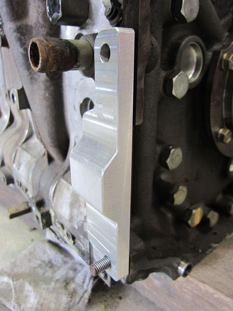
Trial fitting on the dummy block.
The mounting bracket for the Motec C125 dash logger.
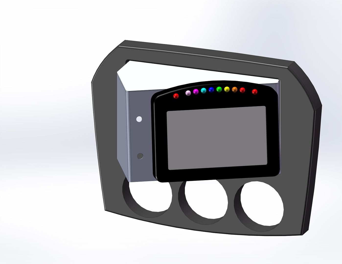
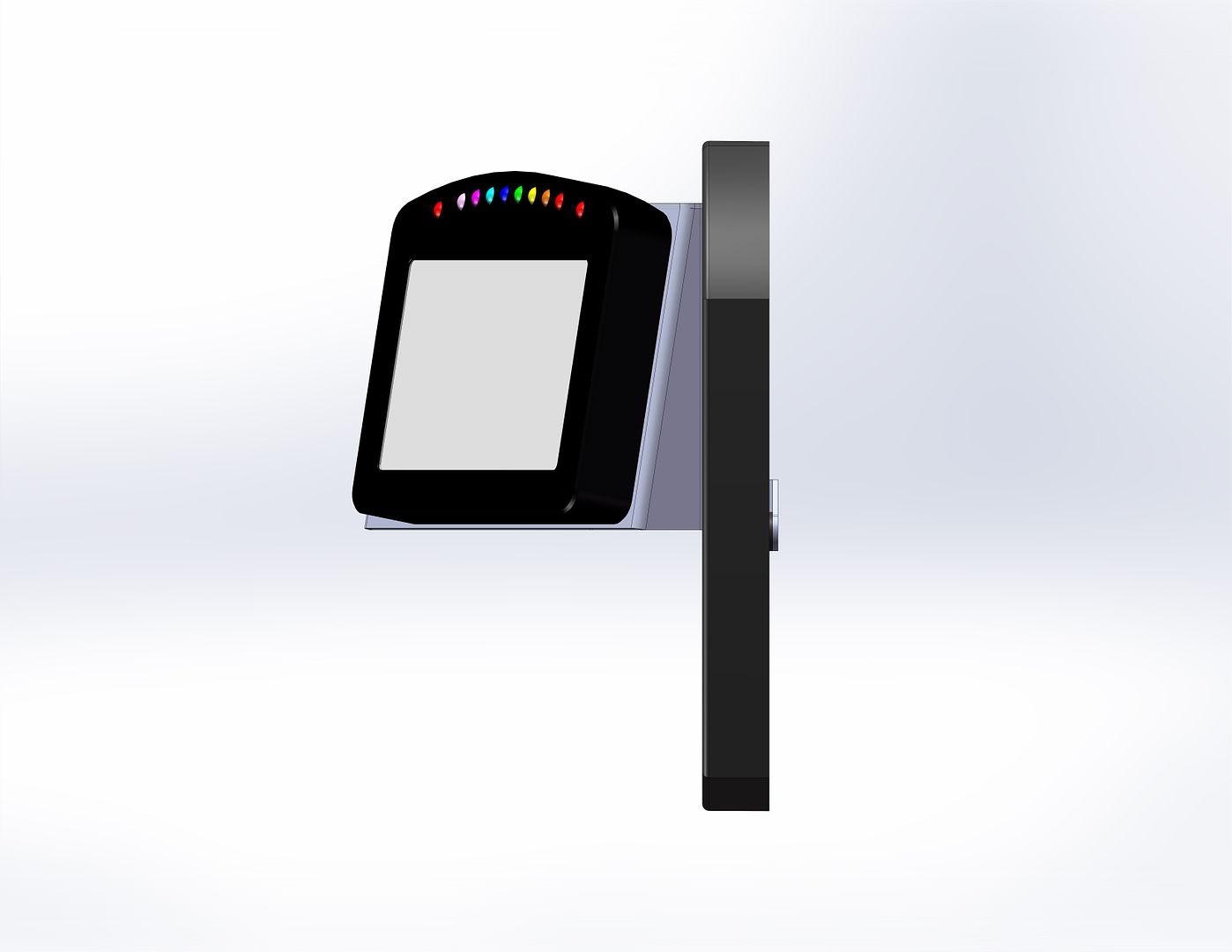
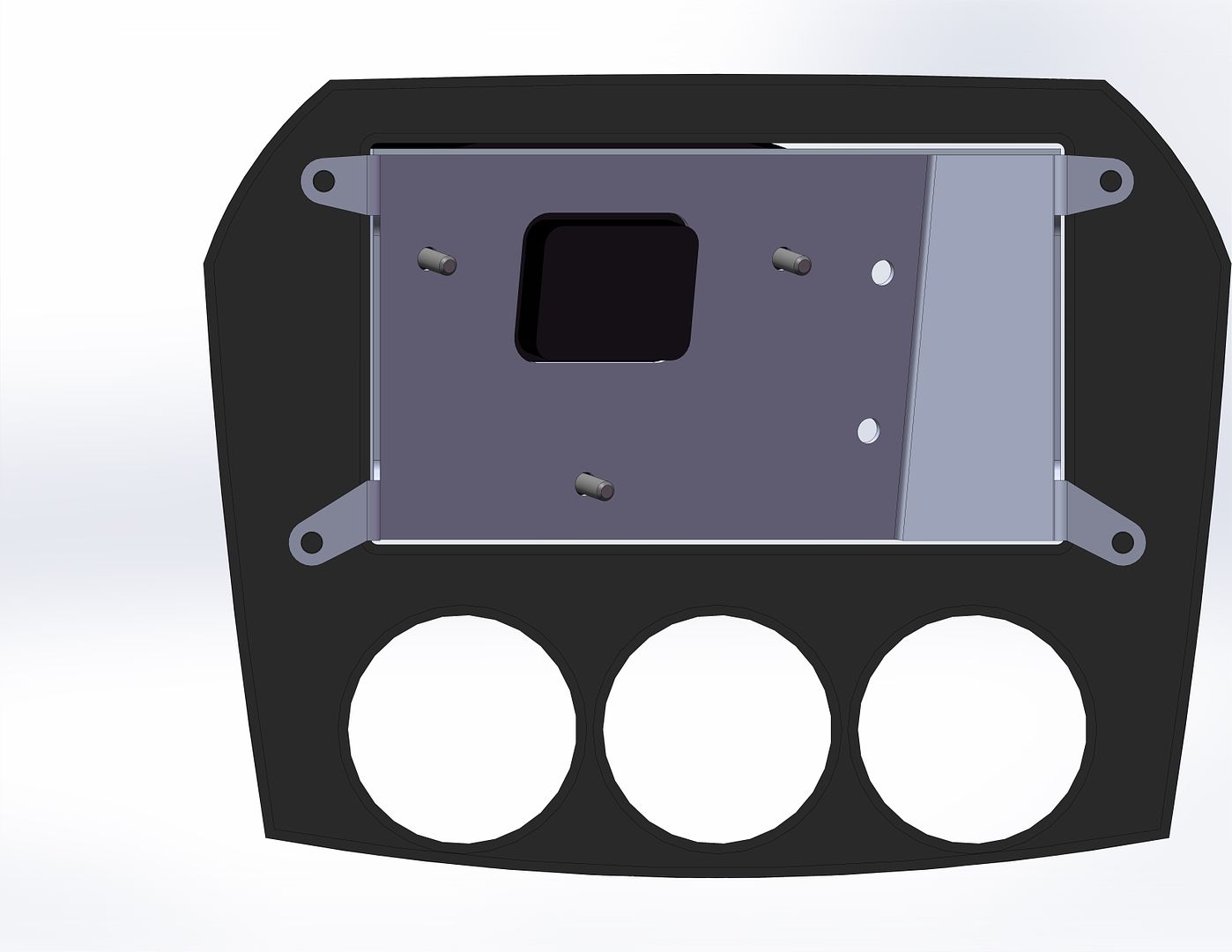

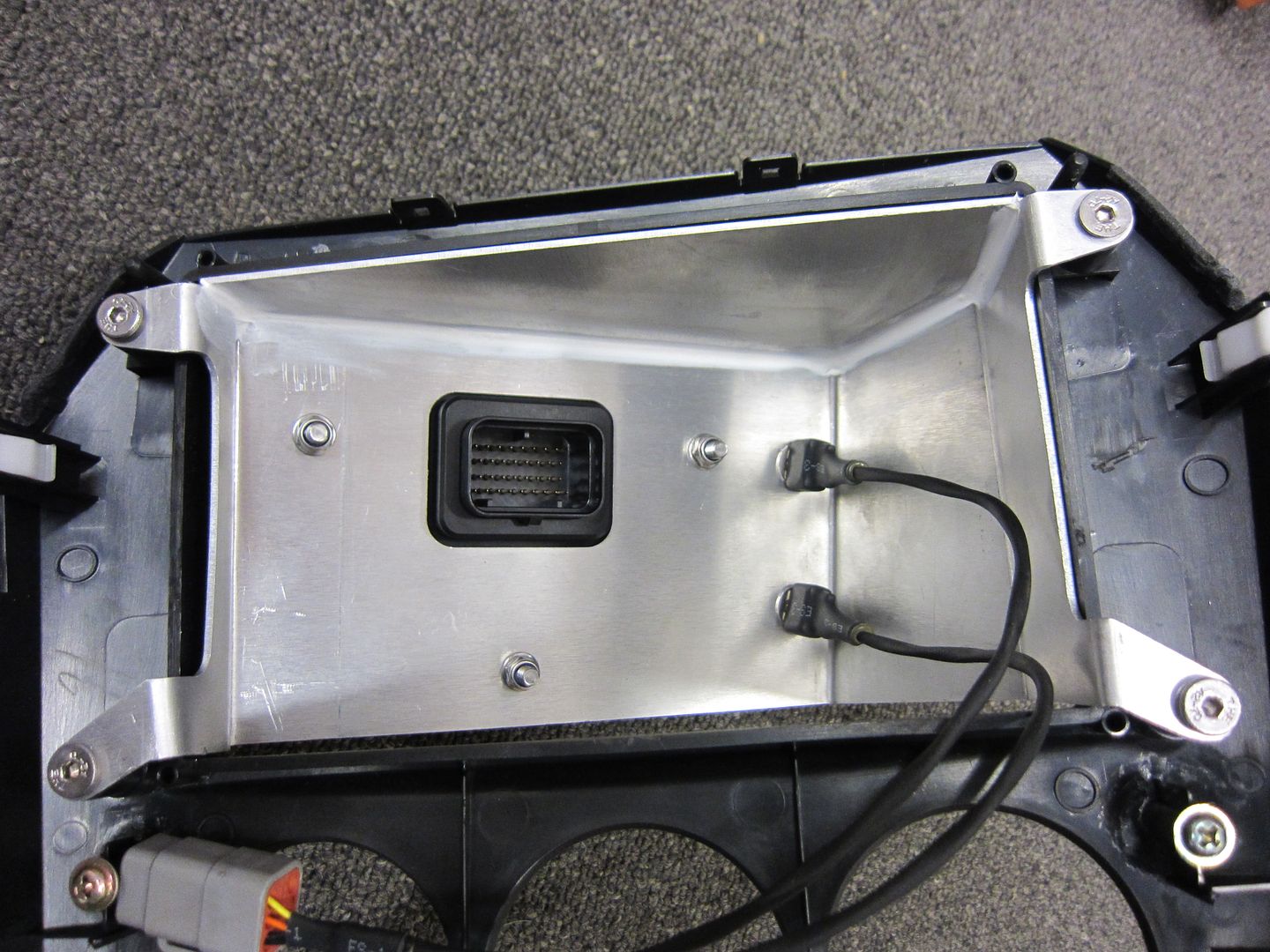
...and finally assembly.
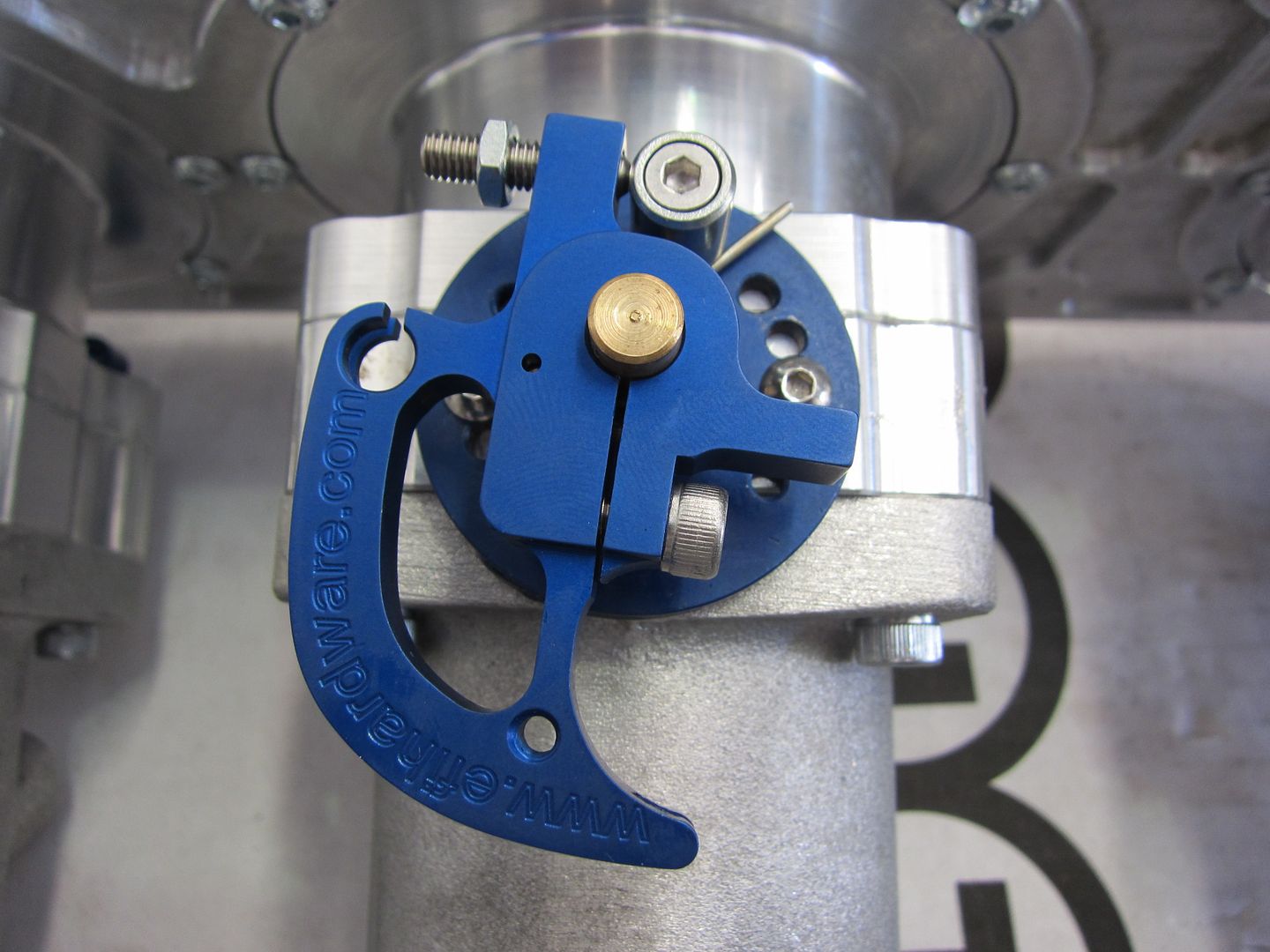
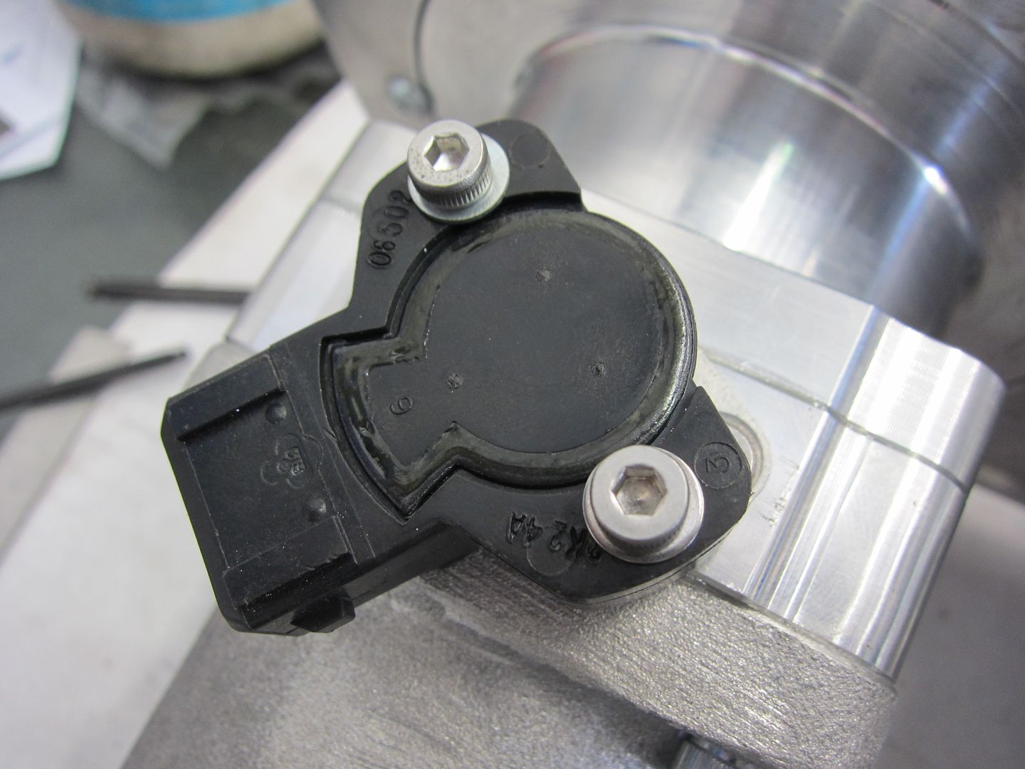
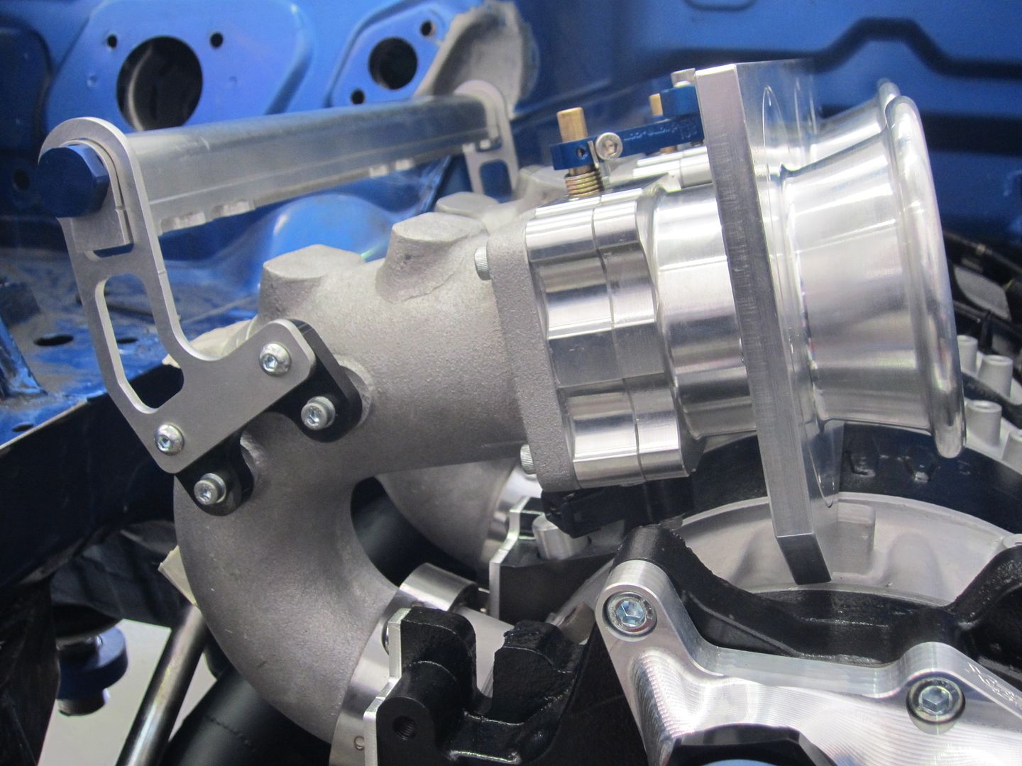
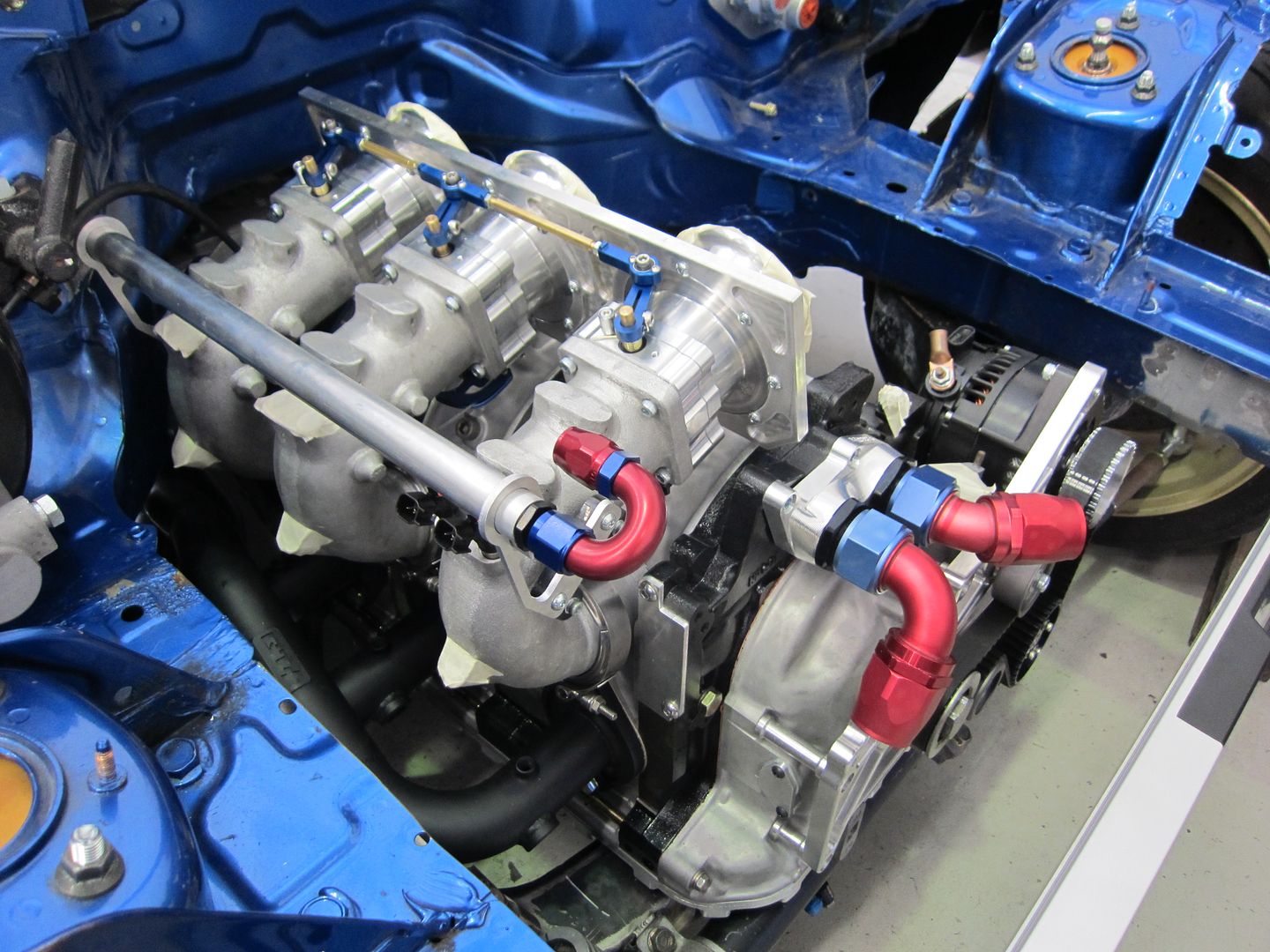
The inlet manifold and throttle linkage assembly has been completed. This includes the TPS unit.
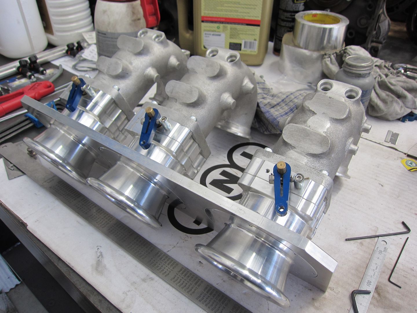
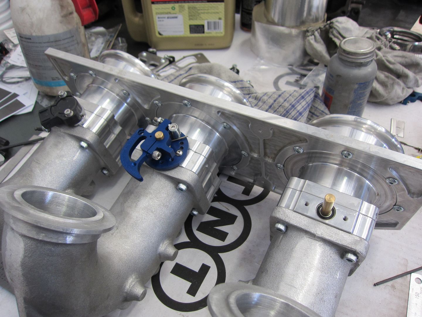
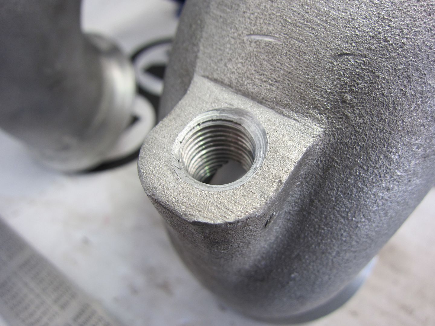
The inlet manifold runners have also been drilled and tapped for the vacuum take-off points.
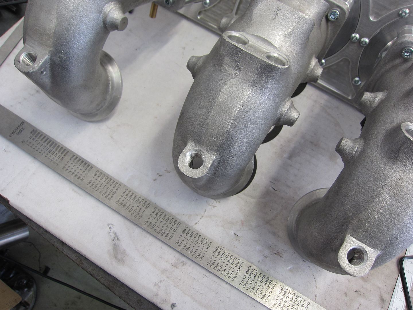
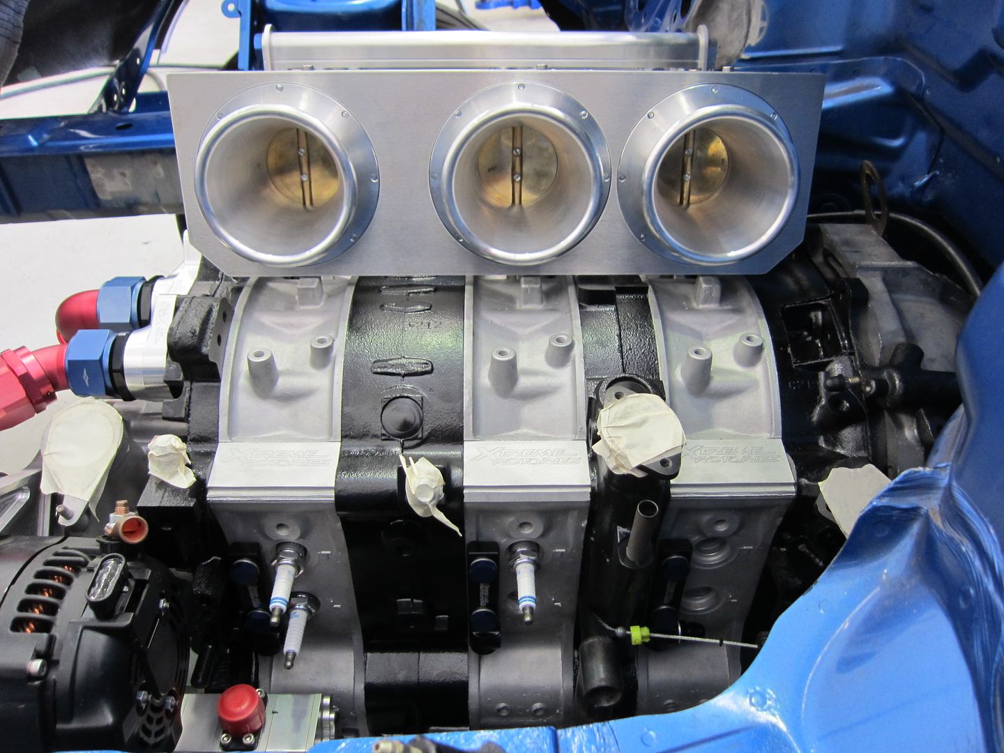
The inlet manifold finally back on the engine.
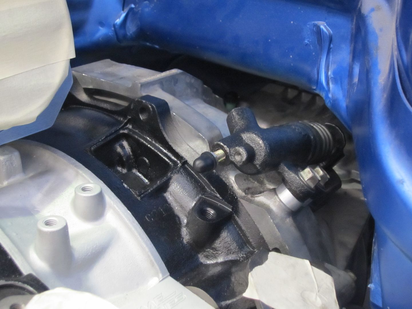
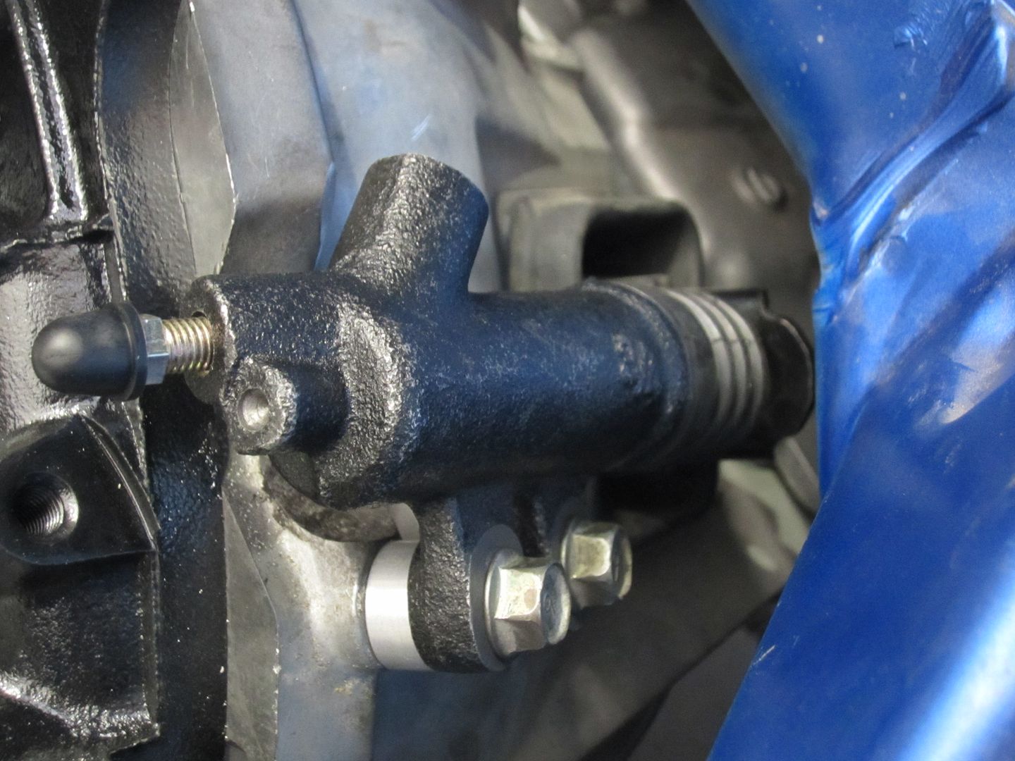
A different clutch slave cylinder was sourced to provide better clearance to the oil take-off block that resides on the rear plate.
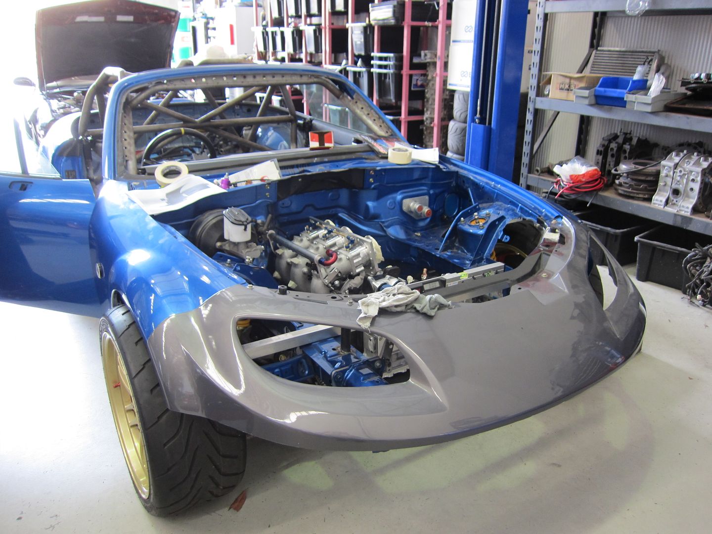
So here she is pushed back to the fab corner awaiting the supply of materials for the front splitter/diffuser and ducted cooling air system.
Cheers,
Danny
Starting with design...most effort has been put into the heat exchanger assembly which integrates with the front splitter/diffuser. I don't think I've put up up photos of the engine coolant radiator and engine oil cooler. So here they are.


So basically the concept is that the two heat exchangers are welded together to form an air tight box that is part of the ducted cooling air system. A Spal thermo-fan is also included to provide air flow whilst the vehicle is stationary or has low road speed.


Materials for the above and the rest of the ducted air system (below) should be ordered this week.


Manufacturing wise, the following has been completed.
Adaptor flange for the crankcase breather line on the intermediate plate (previously the oil filler neck).


...and installed.

The adaptor to mount the RX-8 starter motor. Just needs to be drilled and tapped with a bell housing bolt thread once measured.


Trial fitting on the dummy block.


The mounting bracket for the Motec C125 dash logger.


...and finally assembly.
The inlet manifold and throttle linkage assembly has been completed. This includes the TPS unit.


The inlet manifold runners have also been drilled and tapped for the vacuum take-off points.


The inlet manifold finally back on the engine.


A different clutch slave cylinder was sourced to provide better clearance to the oil take-off block that resides on the rear plate.


So here she is pushed back to the fab corner awaiting the supply of materials for the front splitter/diffuser and ducted cooling air system.

Cheers,
Danny
-
MattR

- Racing Driver
- Posts: 1305
- Joined: Wed Feb 25, 2009 11:26 pm
- Vehicle: NA6
- Location: Brisbane
Re: NC Track Car - In the Build
Danny I take it the air will be pushed through the two heat exchangers in a sealed duct and then sucked out through a sealed vent in the bonnet in an appropriate low pressure area, and basically the same for the engine intake? Will you be looking at running the front splitter into an undertray to cover the whole underneath of the engine bay to minimise the air getting into the engine bay?
As per usual the standard set is basically unobtainable for the rest of us.
-
Lokiel

- Forum legend
- Posts: 4126
- Joined: Thu May 28, 2009 2:39 pm
- Vehicle: NB SE
- Location: Brisbania
Re: NC Track Car - In the Build
orx626 wrote::
:
Danny
 Whoah, biggest oil cooler EVER
 Makes my little Setrab seem insignificant.
Don't worry about dying, worry about not living!
Garage Thread: http://www.mx5cartalk.com/forum/viewtopic.php?f=57&t=76716
Garage Thread: http://www.mx5cartalk.com/forum/viewtopic.php?f=57&t=76716
-
orx626
- Forum sponsor
- Posts: 1774
- Joined: Thu Sep 23, 2004 8:26 am
- Vehicle: NC - Rotary
- Location: Brisbane - Northside
- Contact:
Re: NC Track Car - In the Build
MattR wrote:Danny I take it the air will be pushed through the two heat exchangers in a sealed duct and then sucked out through a sealed vent in the bonnet in an appropriate low pressure area, and basically the same for the engine intake?
Hi Matt, yes that is exactly what I'm doing with the cooling airflow. I'm yet to design the engine air intake.
MattR wrote:Will you be looking at running the front splitter into an undertray to cover the whole underneath of the engine bay to minimise the air getting into the engine bay?
The open class rules limit front aero extending behind the front axle centreline.
Cheers,
Danny
-
orx626
- Forum sponsor
- Posts: 1774
- Joined: Thu Sep 23, 2004 8:26 am
- Vehicle: NC - Rotary
- Location: Brisbane - Northside
- Contact:
Re: NC Track Car - In the Build
Lokiel wrote:
Makes my little Setrab seem insignificant.
...because rotary!
-
orx626
- Forum sponsor
- Posts: 1774
- Joined: Thu Sep 23, 2004 8:26 am
- Vehicle: NC - Rotary
- Location: Brisbane - Northside
- Contact:
Re: NC Track Car - In the Build
monty11ez wrote:I had to make an account just so I could post in this thread. I was following it over on rx8club, but this seams to be updated more frequently. Anyways I am a huge fan! One of these days I'm going to put a rotary into an NC as well. I can't wait for future updates.
Thanks Monty. Yes, I keep this thread current. I stopped updating the rx8club forum thread once I changed the engine specification from the supercharged 13B-MSP to the 20B PP.
Some of the processed materials for the front splitter/diffuser and ducted cooling air system arrived late yesterday.
In anticipation I grabbed the two heat exchangers from my office.

The items that required rolling and pressing were completed first. They were the upper and lower panels of the inlet duct. This is the lower with rolled edge.

This is the pressed upper panel.

The completed upper and lower panels.

I employ mortise and tenon quite a bit when I design. It's effectively self-jigging and reduces fabrication error. You can see the tenons in the below photo.

This is one of the side plates with the mortises.

Connecting the upper and lower panels to the side plates.

Tack welding the assembly.

The pinch weld was then trimmed to length and trial fitted. Pinch weld is used to minimise leakage of cooling air from the duct.

I'm very, very happy with the outcome!


The next fabrication job is to build the heat exchanger assembly unit (joining the coolant radiator and oil cooler together).
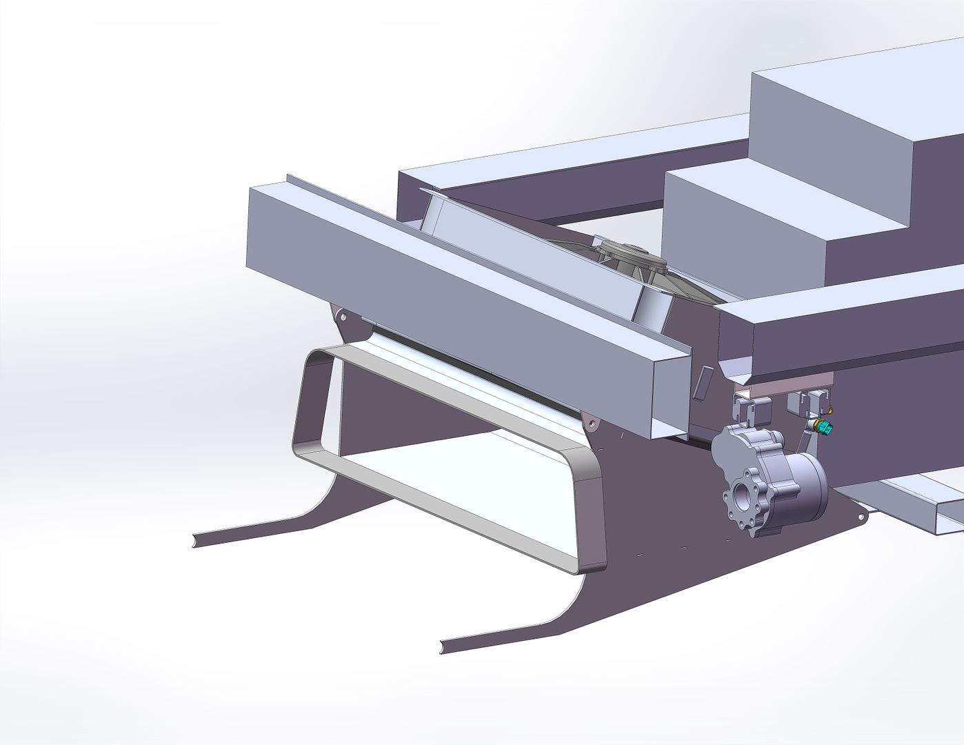
Design of the mounting bracket assembly for the electric water pump has continued.


Cheers,
Danny
-
plohl

- Racing Driver
- Posts: 1922
- Joined: Wed Oct 14, 2009 12:13 am
- Vehicle: NA8
- Location: Brisbane
Re: NC Track Car - In the Build
orx626 wrote:
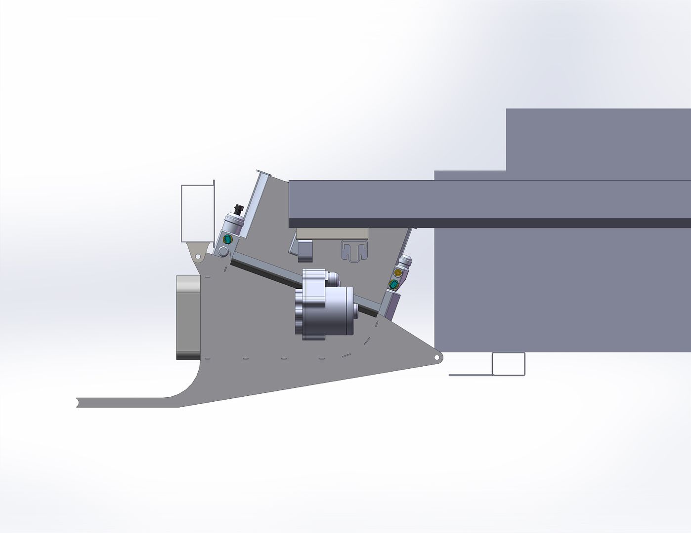
Is i just the angle, or are you going to have some trouble fitting the AN fitting on to the pump?
Cheers,
plohl
plohl
-
orx626
- Forum sponsor
- Posts: 1774
- Joined: Thu Sep 23, 2004 8:26 am
- Vehicle: NC - Rotary
- Location: Brisbane - Northside
- Contact:
Re: NC Track Car - In the Build
plohl wrote:Is i just the angle, or are you going to have some trouble fitting the AN fitting on to the pump?
It's just the angle Shane. I've already trial fitted the AN adaptors to the water pump inlet and dual outlets.
Cheers,
Danny
-
plohl
- Racing Driver
- Posts: 1922
- Joined: Wed Oct 14, 2009 12:13 am
- Vehicle: NA8
- Location: Brisbane
Re: NC Track Car - In the Build
Damn 2d pictures of 3d objects  -20?
-20?
Might have to start uploading e-drawings for us haha
Might have to start uploading e-drawings for us haha
Cheers,
plohl
plohl
-
orx626
- Forum sponsor
- Posts: 1774
- Joined: Thu Sep 23, 2004 8:26 am
- Vehicle: NC - Rotary
- Location: Brisbane - Northside
- Contact:
Re: NC Track Car - In the Build
plohl wrote:Damn 2d pictures of 3d objects
Yes the inlet is -20 and one of the two outlets is -20. The other outlet for the coolant delivered directly to the spark plug regions is -16.
-
16bit

- Speed Racer
- Posts: 2346
- Joined: Wed Nov 29, 2006 1:51 pm
- Vehicle: NB8A - Supercharged
- Location: Brisbane Southside
Re: NC Track Car - In the Build
shits getting real.
this would have to be the most engineered project i have seen outside of a professional race team.
even more then some of those too i am sure!
i suppose when you have time and the skill this is what happens!
this would have to be the most engineered project i have seen outside of a professional race team.
even more then some of those too i am sure!
i suppose when you have time and the skill this is what happens!
98 evo gold - rotrexed and loving it.
This post has been printed using recycled pixels
This post has been printed using recycled pixels
-
orx626
- Forum sponsor
- Posts: 1774
- Joined: Thu Sep 23, 2004 8:26 am
- Vehicle: NC - Rotary
- Location: Brisbane - Northside
- Contact:
Re: NC Track Car - In the Build
monty11ez wrote:Well, it practically is a professional race team.
Wow! The last three weeks have gone like there was no tomorrow!
Progress has been a bit staggered with some aspects of the build being a bit stop-start. As some of you may have seen I had the car on display at AusGarage's first ever Motorshow which was on the 1st February at the RNA Showgrounds. So the week leading up to the event my focus was on completing as much of the "visual" build as I could.
Craftsquare carbon mirrors were dusted off and put back on.

BTW this is the thermofan I'm using. It's a SPAL VA01-AP70/LL-66A 12A

Progress on the front splitter/diffuser was really good with everything going together as designed. I know there's a few items in this photo...the important one is the bent bit of aluminum tube. This is the leading edge of the front splitter.

...and welded in position between the upper and lower flanges. There's plenty of stiffness and strength to transfer the downforce back into the chassis.


Oh! I love these Clico rivets/temporary fasteners! This is the integrated splitter and heat exchanger duct.

In place on the car.

...with the radiator in place.


The finished oil take-off block.


...and the oil distribution lines.


...the inlet manifold vacuum balance lines (a vacuum reservoir is to be added).

...exhaust EGT sensors and Lamba sensor bungs installed.

...completed fuel rail assembly and lines.


A bit of ol' school on the Crank Angle Sensor.

...the completed starter motor bolt block.

Be gone fly-by-wire!!!


All of the lines for the dry sump and the fuel system were also completed. Suitable fixing of the lines and filters is to be completed.


I can't remember if I'd put up any photos of the front and rear uprights. So here they are.


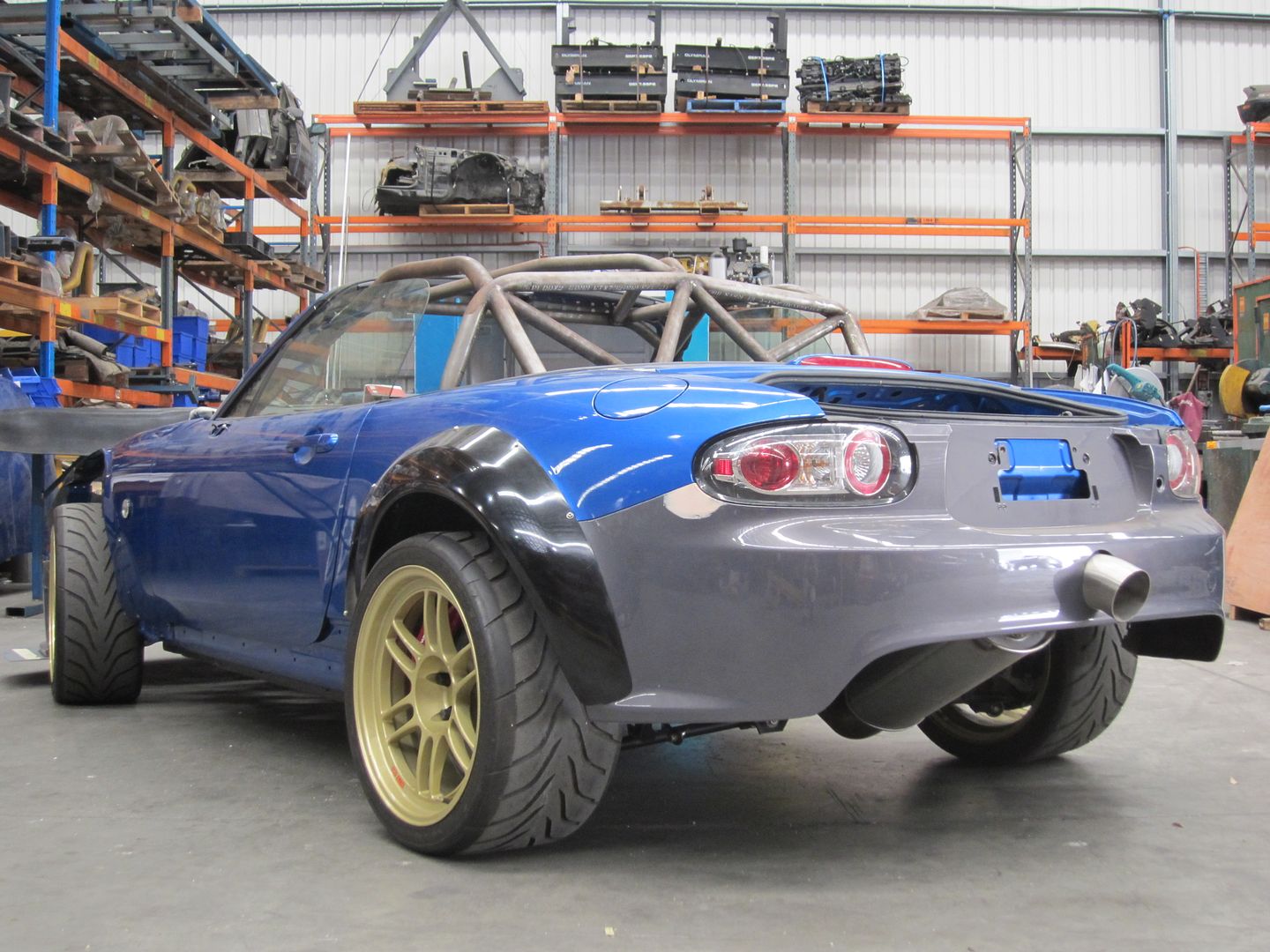
So as mentioned above, I put the vehicle on display in the motorsport section at the first ever AusGarage Motorshow. All I can say is WOW as to how quickly this photo went viral within two hours of posting it online. I haven't kept track of how many likes, shares and blog stories...but it has been quite overwhelming and humbling. The feedback and support for the build has been nothing short of unbelievable!

The week before last I dropped in at RE Amemiya's Tokyo workshop and they had even seen this photo online! The two mechanics that look after "Hurricane" were very impressed with the build. This really meant a lot to me as I hold RE Amemiya's car building expertise in the highest regard.
BTW...this is Hurricane.

Here are some other photos from the Motorshow. You'll see other bits and pieces have been completed. The seat is a Bride Gardis III that I'm waiting on a rail for.


So the critical path is now to finish the heat exchanger assembly, install the electric water pump and plumb the remaining lines. From here the wiring can be installed and hopefully start the engine for the first time (hopefully only a few weeks away).
Then there's the body work....lets just not go there right now.
Cheers,
Danny
-
Okibi

- Speed Racer
- Posts: 10912
- Joined: Thu Aug 21, 2003 11:00 am
- Vehicle: NB SE
- Location: Perth, Western Australia
- Contact:
Re: NC Track Car - In the Build
Great update, glad to see you get much deserved attention and respect.
If you had access to a car like this, would you take it back right away? Neither would I.
-
plohl
- Racing Driver
- Posts: 1922
- Joined: Wed Oct 14, 2009 12:13 am
- Vehicle: NA8
- Location: Brisbane
Re: NC Track Car - In the Build
Yo Danny,
Were there any major reasons to get rid of the Fly-by-wire, or just a simplification? You would have been able to set up some cool stuff with the m800.
Were there any major reasons to get rid of the Fly-by-wire, or just a simplification? You would have been able to set up some cool stuff with the m800.
Cheers,
plohl
plohl
Who is online
Users browsing this forum: No registered users and 16 guests


