Last weekend's efforts:
I've been focusing on implementing the next generation of my DIY sensor box and needed to wire-up two temperature sensors to measure temperature inside and outside my airbox since I want to find out how effective it is and whether I need to add additional insulation to it.
To do this I needed to route the wiring from the sensor box to the airbox.
There's a grommet on the hot-side firewall to route wiring into the passenger footwell:
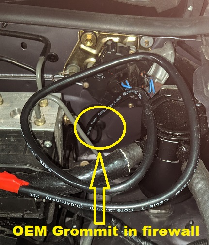
I'd used this before when I was using the Adaptronic ECU and it was a pain in the arse trying to thread individual wires since you also need to get past the footwell's insulation layer.
It was much easier using a sheathed cable with multiple wires.
Sequential (vs OEM wasted-spark) firing of the coils has always been a goal of mine which requires 2x additional wires to the ECU that control SparkC and SparkD so I figured I'd use a 6-core cable, 2x each for the two temperature sensors and 2x for the igniters.
There is no way that I'd be able to thread the 2x igniter wires separately later.
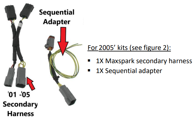
I received an e-mail from DIYAUTOTUNE regarding their new MaxSpark product which included everything needed to install an aftermarket CNPS using wasted-spark or sequential firing, including coils, mounting bracket and harnesses, as well as configuration details for the MS2/3 regarding the coils.
The coils are new AMP EFI IGN-1A coils, not 2nd-hand GM or Toyota coils and DIYAUTOTUNE have worked with them to define the correct settings which is a good thing (the GM and Toyota settings have largely been deduced by users).
https://www.diyautotune.com/product-releases-updates/max-spark-the-ultimate-miata-ignition-upgrade/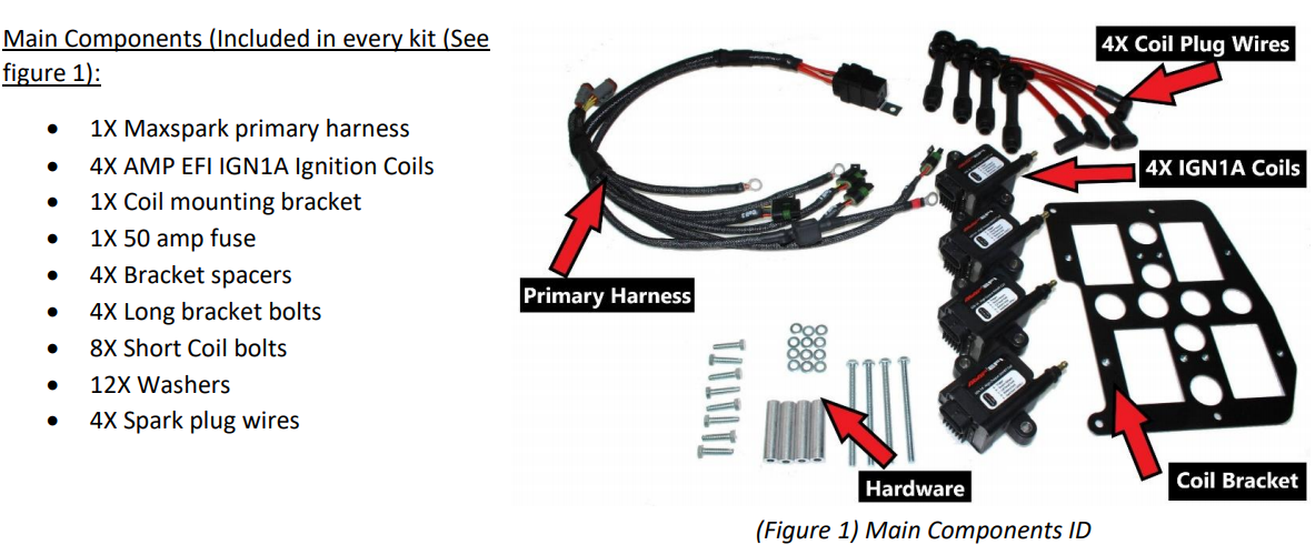
My biggest concern was "would it allow me to retain my 3-point Carbing front strut brace"?
I love it since I use it to mount a brake master-cylinder brace and it's handy to lean on when working in the engine bay - plus it looks great IMO!
Looking at the photos on the site made me think it would fit OK so I bought the kit since making harnesses for the coils is time consuming and you need to do it properly, you can't afford to have any shorts or wires detaching from their pins.
My first attempt at a wasted-spark harness was a bit dodgy and my 2nd attempt was over-engineered, I should have used a smaller wire gauge which made fitting them to the coil plugs harder than it should have been - it's strong as hell though, none of those wires will ever pull out.
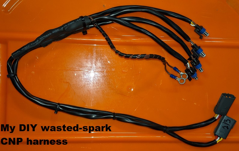
It's quite long which allowed me to tuck it away out of site where I wanted; the first harness was shorter which meant I could only stuff the wiring behind the motor.
I really didn't want to make a new harness and prefer to keep my existing harness for a wasted-spark setup since I know it works.
Thankfully all bolts supplied are metric - I didn't use any of them though!
The first thing I noted was that the long bolts used to attach the mounting plate to the rocker cover were a little too short for my liking, when bolted in fully I could feel from underneath that they were at least one thread short and those bolts should only be lightly torqued (~55 In/lbs).
I bought some longer bolts from Bunnings Motorsport that are 5mm longer and these protrude from underneath by about 2mm:
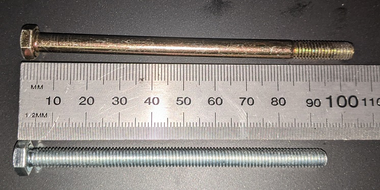
The short bolts for mounting the coils to the mounting plate are way too long so I used some short Allen bolts instead (which still needed some trimming because adding lightness is important).
With this kit, before bolting on the mounting plate, you MUST first thread all the ignition wires through the mount plate, connect them to the coils and plug in the rear two ignition wires - you CANNOT do it later. The instructions do make this clear though so I had to smack myself in the back of head for making this mistake initially.
My DIY solution made it hard to disconnect the plugs from the coils, I needed a long flat screwdriver to unclip them before sliding them off, but the MaxSpark kit is MUCH harder to change components, you need to unbolt the mounting plate.
The MaxSpark kit harness requires an additonal 12V source and includes an in-built fuse and relay.
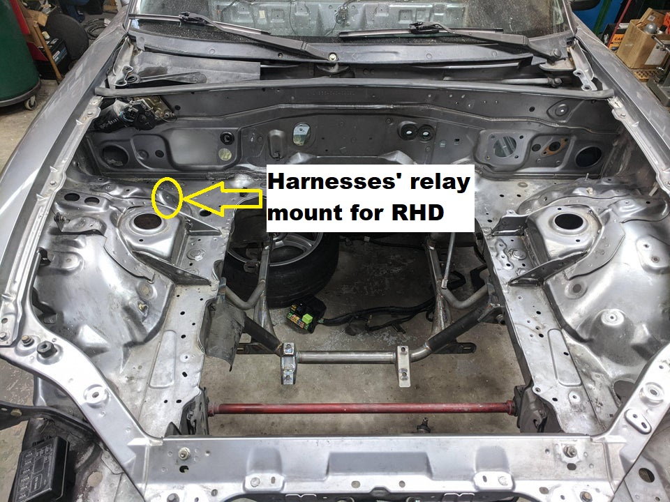
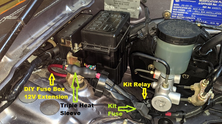
The documentation says to mount the relay on the coldside firewall but we RHDs have no room there.
Luckily there's an OEM 6mm threaded hole on a 45* slope on the coldside suspension mound (directly below the from of the brake master cylinder) so I used that - you don't want to mount relays horizontally on the shelf because water may pool up around them).
The additional 12V source was the biggest hurdle.
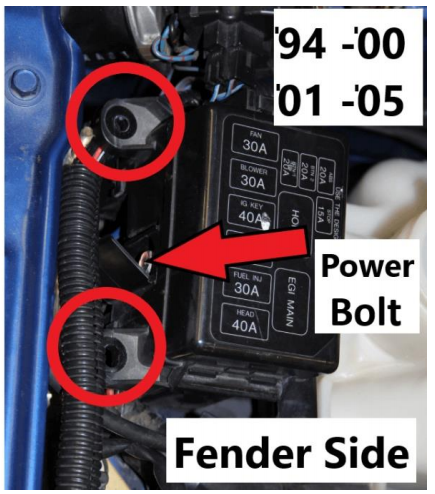
The instructions recommended the following for my model:
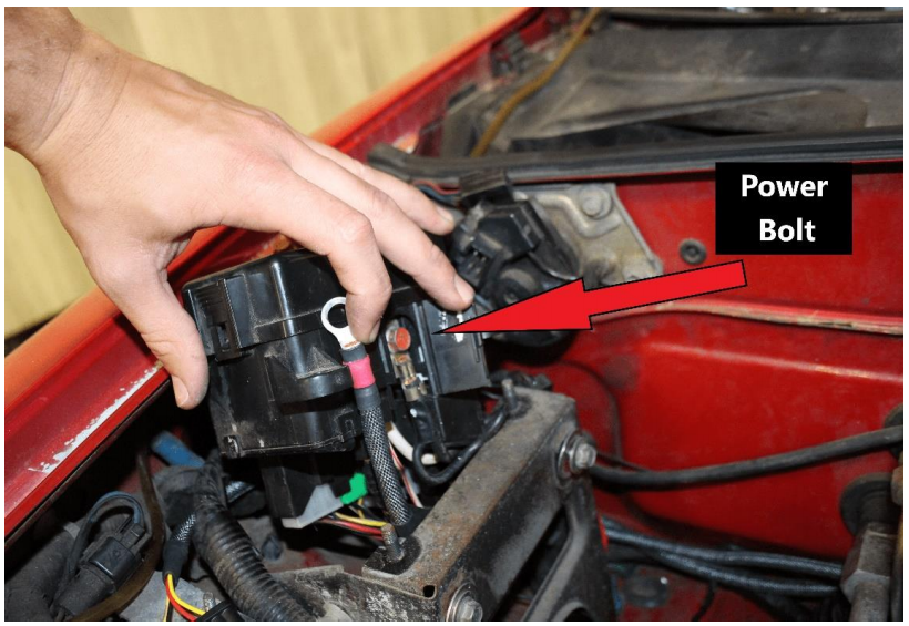
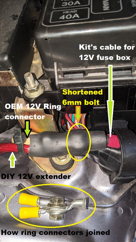
The OEM ring connector to this bolt (yes, even mine has red paint on it) has 2x wires attached, one being quite thick.
The instructions indicate that there is a "door" to access this bolt.
On my car, this isn't the case, the top of the fusebox unclips and can be pulled off in one piece - there is no door access to that bolt.
The OEM wiring to the bolt is from directly underneath and there is no room to include it and the new 12V massive cable of the new harness to it!
I had to make a cable extension from that bolt, outside of the fuse box and joined the existing OEM 12V wiring and new harness 12V wire to it using ring connectors, a shortened M6 nut and bolt and 3x layers of heat-shrink:
The instructions recommend ground points for the harness:
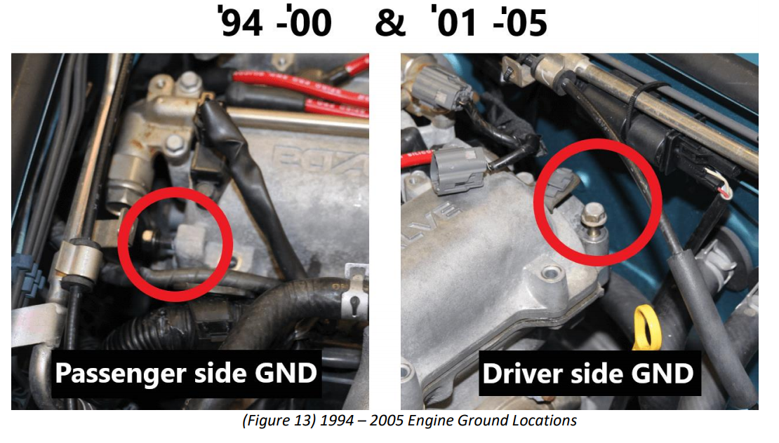
For my original DIY wasted spark implementation I used the '94-'00 ground point on my MSM and it was still more convenient to use it so I used that instead of the '01-'05 recommendation. I know it works and can switch it over easily enough if needed.
The extra wiring is all zip-tied behind the engine, not as slick as before though

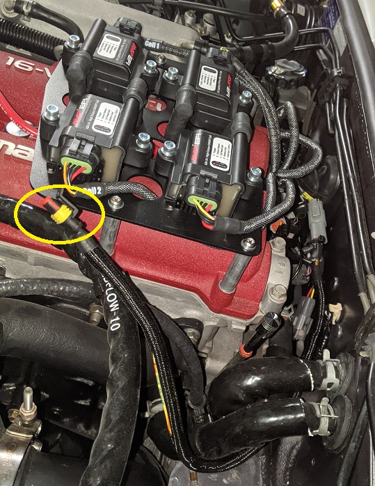
The circled yellow plug is the 2-pin SparkC and SparkD connector for the MS3.
Here's what it looks like so far:
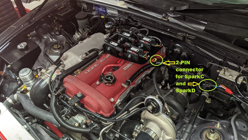
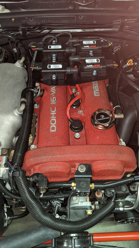
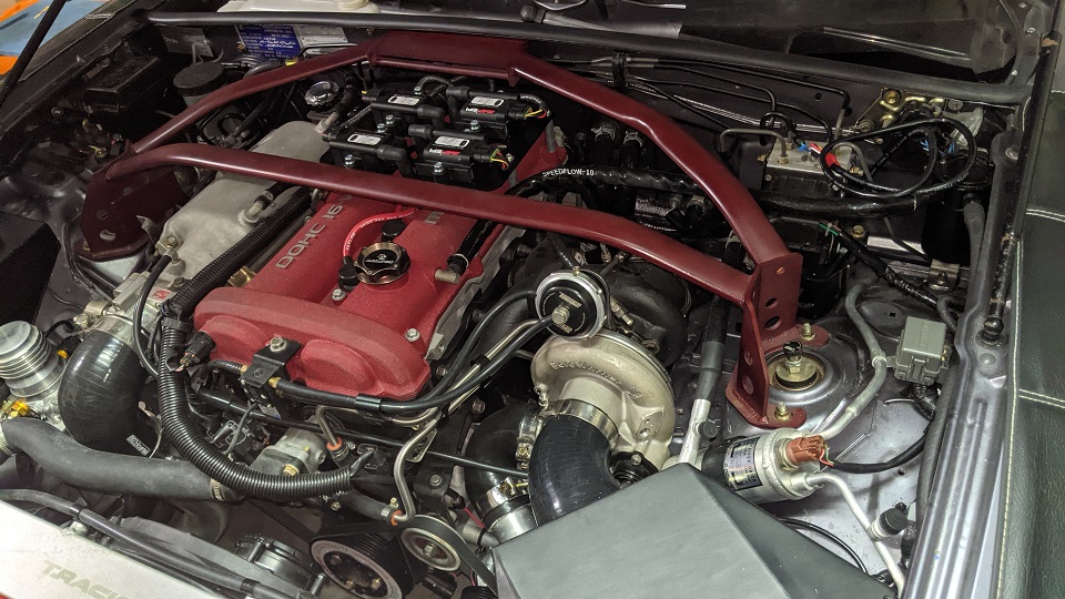
I still need to wire up the MS3 to see if it all works - if it doesn't, I can easily revert to the previous wasted-spark solution.
... and I'd forgotten about the 2x temperature sensors. One will be mounted inside the cold air box, the other just outside of it. They cannot be mounted to the same point/bracket since it may affect the readings.
