Lokiel's "Gina" (2004 Titanium SE)

Chat to do with your MX5/Miata/Eunos Garage Ride(s).

Moderators: timk, Stu, zombie, Andrew, The American, Lokiel, -alex, miata, StanTheMan, greenMachine, ManiacLachy, Daffy

User avatar
Lokiel
Forum legend
Posts: 4126
Joined: Thu May 28, 2009 2:39 pm
Vehicle: NB SE
Location: Brisbania

Re: Lokiel's "Gina" (once a 2004 Titanium SE) Recreated AGAIN

Postby Lokiel » Tue Jun 05, 2018 8:35 pm

Originally posted by Lokiel, Sun Sep 24, 2017 5:40 pm

Originally posted by Lokiel, Wed Mar 29, 2017 12:05 pm[

]*** BREAKING NEWS ***[/

Read from Post #468 thru #473: http://www.miataturbo.net/prefabbed-turbo-kits-3/trackspeed-na-nb-efr-turbo-kits-available-now-86287/page8/#post1401973

Image


Originally posted by ManiacLachy, Wed Mar 29, 2017 12:06 pm[

I just read that thread a minute ago. Oh man!


Originally posted by Nevyn72, Wed Mar 29, 2017 12:07 pm[

Magpie wrote:We will host a special Dodgy Day in Brisbane finish Gina! :)


Fixed that for you. :mrgreen:


Originally posted by Lokiel, Thu Mar 30, 2017 9:10 am[

So you guys are saying:
Image

If I finish the car, what'll I do with all my spare time?

On a similar note, thinking about buying this for Magpies' place on Dodgy Days:
Image
http://www.ebay.com/itm/GIT-R-DONE-Street-Sign-git-er-done-redneck-hick-gift-funny-gag-joke-gift-south-/170730844017


Originally posted by Okibi, Thu Mar 30, 2017 9:17 am[

Lokiel wrote:...If I finish the car, what'll I do with all my spare time?..


Track days :mrgreen:


Originally posted by Lokiel, Thu Mar 30, 2017 10:13 am[

Okibi wrote:
Lokiel wrote:...If I finish the car, what'll I do with all my spare time?..


Track days :mrgreen:

sh*t - forgot all about those, it's been so long!
Don't worry about dying, worry about not living!
Garage Thread: http://www.mx5cartalk.com/forum/viewtopic.php?f=57&t=76716

User avatar
Lokiel
Forum legend
Posts: 4126
Joined: Thu May 28, 2009 2:39 pm
Vehicle: NB SE
Location: Brisbania

Re: Lokiel's "Gina" (once a 2004 Titanium SE) Recreated AGAIN

Postby Lokiel » Tue Jun 05, 2018 8:35 pm

Originally posted by Lokiel, Sun Sep 24, 2017 5:41 pm

Originally posted by Lokiel, Sun Apr 16, 2017 12:32 am[

After reading that many high-powered turbocharged MX5s using large intercoolers suffer heating issues on the track that require better performing radiators, my paranoia kicked in and I decided to upgrade mine too since I have the Fab9 350hp intercooler, which is pretty big.

I've had a lot of these parts accumulating for some time now, waiting for some free time to install them.

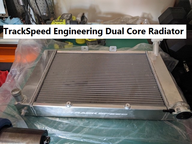
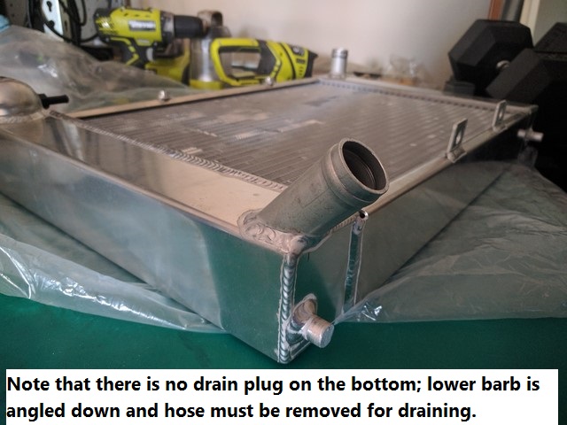
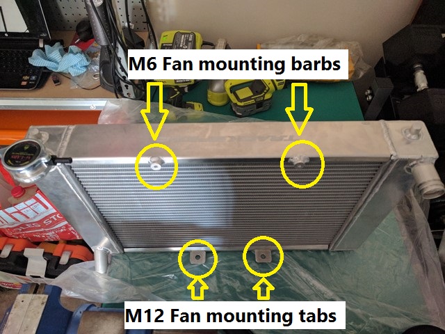
I chose the TSE Dual Core Radiator since it's been track-proven with the EFR6258 turbo and Precision intercooler that's the same size as mine.
Image

Image

Image


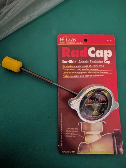
I also bought the TSE radiator cap with sacrificial anode since the stock radiator cap wont fit the TSE Dual Core Race Radiator.
Image

- that anode was bloody hard to get into the end tank!

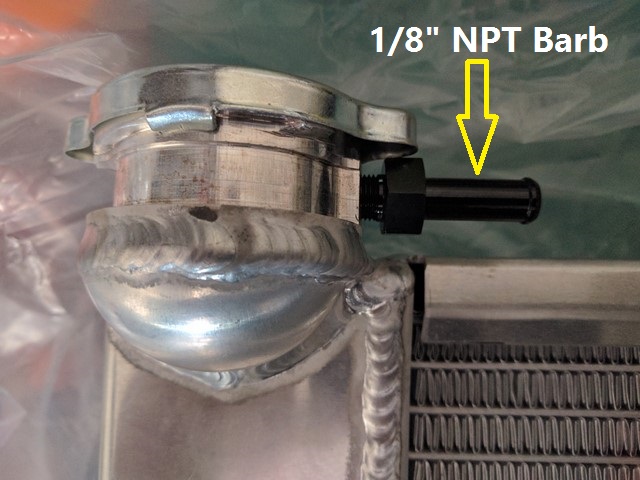
The radiator has a threaded 1/8" NPT hole for the overflow hose.
I rummaged through my spares and found a brass barb, then e-mailed Andrew Kidd (Savington) at TSE if it was OK to use since I was concerned about mixing metals given that I had a sacrificial anode and didn't know if it would affect it.
Andrew said it didn't matter but there SHOULD have been an aluminium barb included with the radiator, taped somewhere in the packaging (he actually said "aluminum").
I guess that in my eagerness when initially unpacking the radiator, it may have fallen out and rolled off somewhere because I never noticed it (there's a lot of packing material in the radiator box).
To be safe, I ordered a 1/8" NPT aluminium barb and used that.
Image


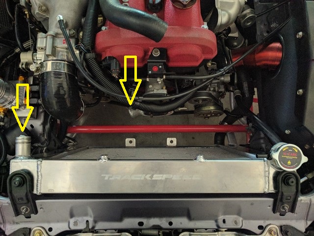
The radiator slotted into place incredibly easily:
Image

The two arrows show the top radiator hose barb and where it needs to connect to on my car.

Like most aftermarket crossflow radiators, it has been optimised for the coolant re-route so the top barb is moved to the edge of the radiator so that the hose can run straight back to the end of the engine bay.

Unfortunately for me, I want to use the OEM cooling routing so need a longer hose and it needs to route around the throttle body elbow.

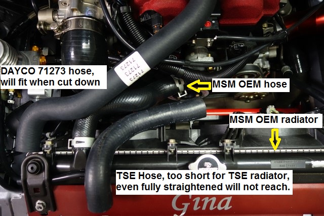
I ordered the TSE top radiator hose but when it arrived it was too short.
I informed Andrew of this, along with the following photo that includes a DAYCO 71273 upper radiator hose that someone else had fitted to their MSM with a similar radiator:
Image

Andrew apologised for the hose, it was sent directly from his supplier, and he refunded me the cost of the hose.
Unfortunately it looks like none of these is going to work since I need it to get around my large intercooler hose.
I may end up needing to create a Frankenstein hose from multiple hoses using a 1.25" hose joiner :(
Any suggestions appreciated (don't plan to do the coolant re-route though).

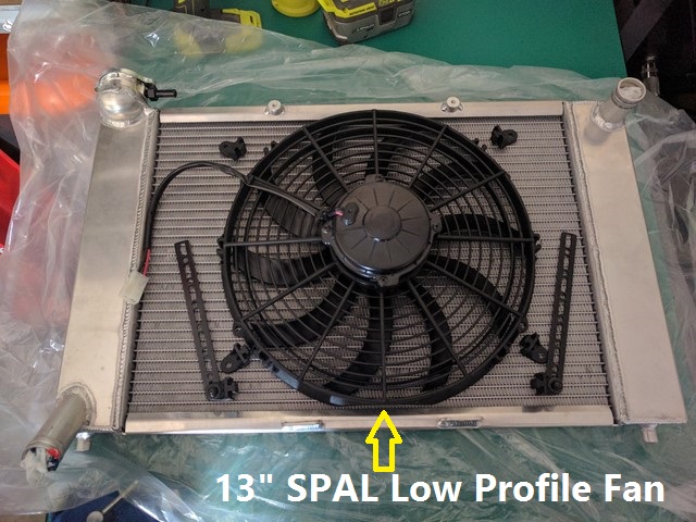
Since the radiator is so deep, the OEM MSM/SE fans wont fit so I ordered a 13" SPAL low profile curved blade fan from the US since I couldn't find it in Australia. This is the fan recommended by TSE for the radiator.
When the fan arrived, it had no mounting tabs so I ordered a few of the different SPAL mounting options since I wasn't sure how I'd mount it.
I ordered 4 of the small 90* brackets, 4 of the metal strip brackets and 4 of the medium 90* brackets with integrated spacers.
Image

- photo shows 2 of the metal strip brackets and 4 of the small 90* brackets.

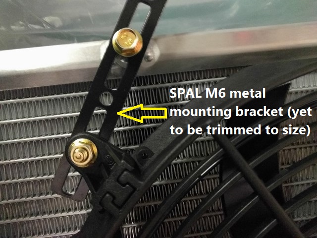
I decided to use 2 of the metal strip brackets for the top mount since they were the easiest to use and fitted well:
Image

Still need to cut them down to size.
The M6 holes aligned perfectly with the fan when it was centred on the radiator.

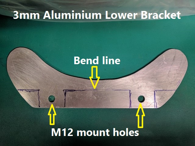
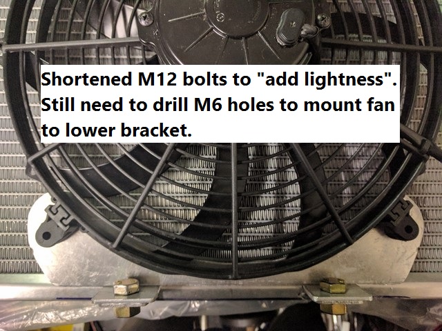
For the bottom radiator mount I need to make a custom bracket.
For strength, I used 3mm aluminium rather than 2.5mm or 2mm aluminium.
Image


Luckily my bender is just wide enough to allow this bracket to fit in it but I could not bend it, the whole solid metal bench tipped towards me as I applied the brake handle.

That didn't work so I cut the bracket at the "bend line", leaving the tabs in place and much less material that needed to be bent.

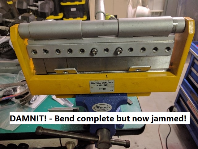
Back in the bender it bent easily but when bent 90*, there was no way to get it out of the bender!
Normally it's just a matter of pushing back on the handle and the cam lobes rotate, lift the bending tongues and I can swing them forward to remove the item.
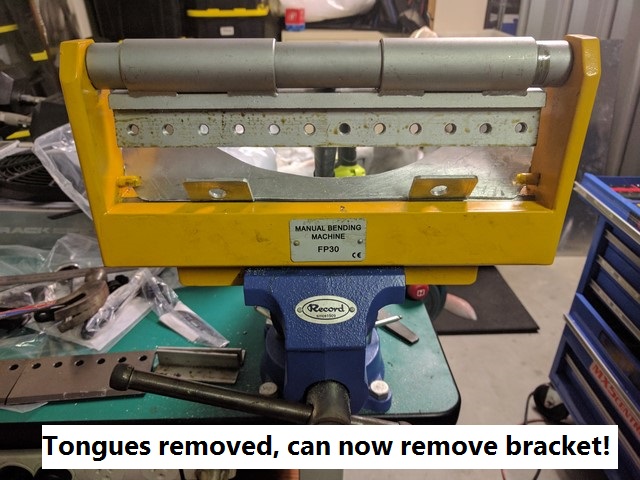
The bender is really only for 2.5mm maximum thickness and with my 3mm piece bent at 90*, the tongues could not swing out of the way and it was stuck!
I had to remove the tongue blades to get my bracket out:
Image

- most of the tongue retaining Allen screws removed in this photo

Image


Lower bracket fitted:
Image


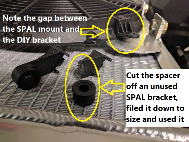
With the small 90* brackets, there's a gap between the SPAL bracket and the DIY bracket.
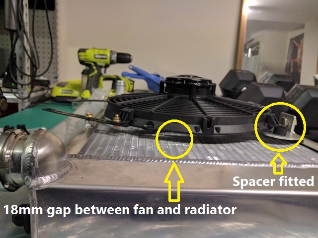
The SPAL medium-length 90* brackets had an integrated spacer so I cut 2 of them off, filed them down to the correct depth and used them as spacers:
Image

Image


There's an 18mm gap between the radiator and fan so I'll need to fill that to ensure that the fan pulls air through the radiator properly.

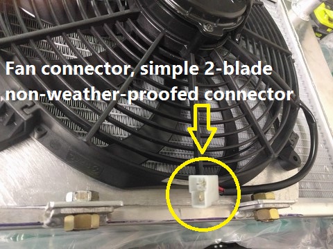
Given that SPAL fans are regarded for their quality, I was surprised that the fan connector was a simple, non-weatherproof 2-blade male connector:
Image


The MSM/SE has 2 fans and each has 2 windings so that the fans can run at 2 speeds.
The SPAL fan is a one-speed fan.
After a lot of reading and pouring over the MSM wiring diagrams, it looks like I can just use the A/C fan and connect both the MSM/SE's +ve wires to the SPAL's +ve wire and the two MSM/SE's GND wires to the SPAL's -ve wire since the relays ensure that the high and low speeds are mutually exclusive.
The MSM/SE already uses a 40A fuse needed to run the SPAL fan.
Don't worry about dying, worry about not living!
Garage Thread: http://www.mx5cartalk.com/forum/viewtopic.php?f=57&t=76716

User avatar
Lokiel
Forum legend
Posts: 4126
Joined: Thu May 28, 2009 2:39 pm
Vehicle: NB SE
Location: Brisbania

Re: Lokiel's "Gina" (once a 2004 Titanium SE) Recreated AGAIN

Postby Lokiel » Tue Jun 05, 2018 8:36 pm

Originally posted by Lokiel, Sun Sep 24, 2017 5:42 pm

Originally posted by Lokiel, Sun Apr 16, 2017 11:18 pm[

... continuing with the TSE radiator install...

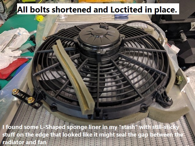
I shortened all the M6 bolts, shortened the top SPAL brackets (and painted them) and Loctited all bolts in place.

Hunting through my "stash" of "that might come in handy one day" stuff, I found some L-shaped foam that had some "still sticky stuff" on one inside edge.
That looked like it may be useful to seal the gap between the radiator and fan.
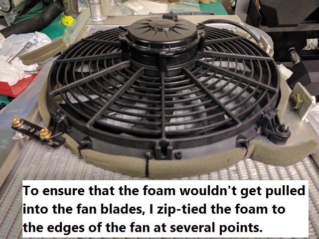
Since the SPAL fan "really sucks", I zip-tied the foam to some of the unused mount points on the edge of the fan to stop the foam from being sucked into the fan.
The 4 mount points I used each had 2 small holes either side of the click-in 90* mounts so I looped a zip-tie through them to help hold the click-in 90* mount in place (my paranoia striking again, worried that they may "vibrate out" at some time in the future):
Image

Image


After mounting the radiator+fan in the car, I needed to address the top radiator hose issue.
2 of my hoses were too short and the DAYCO 71273 hose that a user on the mazda-speed.com form said DID WORK didn't look like it would - I spent a lot of time playing around with it but it always kinked in several places.

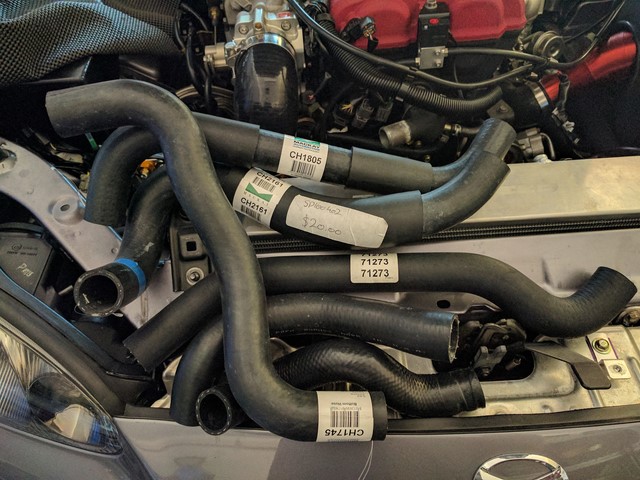
Off to SuperCheap Auto I went and bought 3 hoses that looked like they might fit - I was told I could return the ones I didn't use as long as they weren't modified:
Image

- WHOAH, look at all "dem" hoses, one's GOTTA FIT, surely?

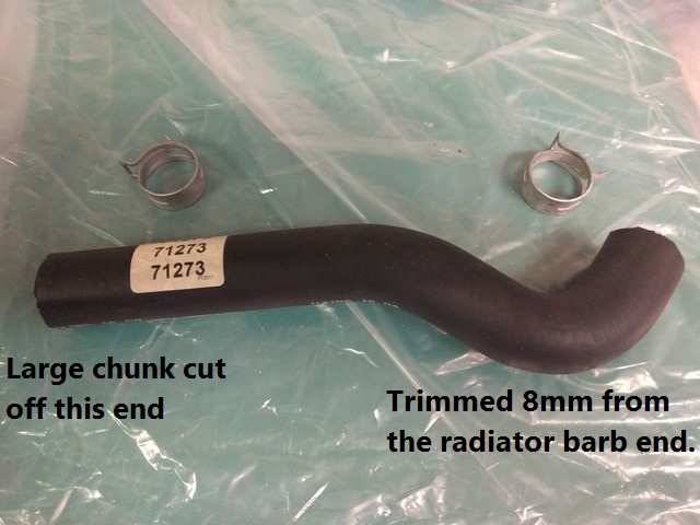
None of the 3 SCA hoses was even close so I decided to revisit the DAYCO 71273 hose again because it was the closest to fitting of any of them.

To minimise the radiator barb end's sharp bend kink, I trimmed about 8mm from it which made a big difference, it looked like it had a chance of fitting after all!
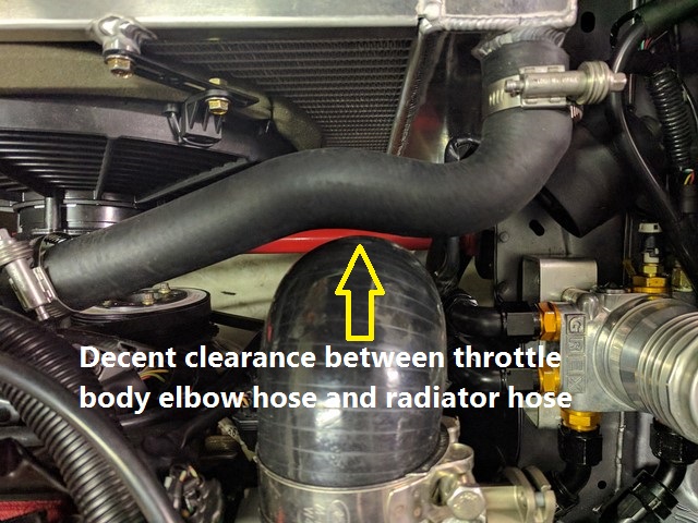
I cut the thermostat hose end to fit and after some hose end twisting VOILA! - it fit well with a decent amount of clearance between the hose and the 90* throttle body silicone hose (2.75-2.5" 90* hose reducer):
Image

- I was planning to use those OEM spring clamps but they were impossible to slide over the hose without firing off at various oblique angles (I learned a long time ago not to do this near the car because they're deadly).

Image


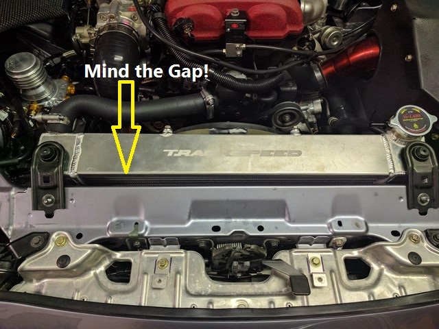
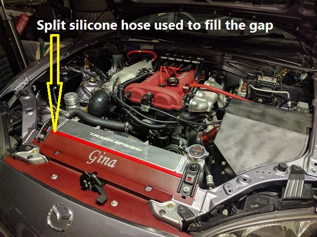
With my radiator cooling panel installed, there's about a 7mm gap between the panel and the radiator.
I still had some red silicone hose back from when I was going through my "red-engine bay" phase so I splt it and attached it to the cooling panel's rear edge to fill the gap:
Image

Image

- the TSE radiator is a HUGE MF!

Hmmm, maybe I should think about anodising the TSE radiator red?

I needed to trim about 12mm from the OEM lower radiator hose to fit the lower barb since the TSE radiator's barb angles downward.

Next task is the fan wiring (and return the unused hoses to SCA).


Originally posted by Magpie, Mon Apr 17, 2017 8:56 am[

Start up test yet? Again impressive attention to detail!


Originally posted by ninerwfo, Mon Apr 17, 2017 9:20 am[

Hey thanks Lokiel! I ordered my TSE radiator last week - so your "how to" comes at exactly the right time - awesome. Good on you for including all the frustrating details as well :) . Most folks I talked to told me I was mad spending that much on a radiator, but like you, I want to keep AC and PS, I have an intercooler as well, AND I want to not be scared away from Queensland Raceway in the middle of summer. This was the only solution I could find that would give me the best chance of doing all that.

Hey, from time of order to delivery, how long did it take to arrive?

Also, am I wrong, but is yours one of the only EFR turbo cars in the country so far? Will you be shooting for 400hp? Does this mean you will be putting in a different box, or will you "torque shape" you power curve like Dann does?


Originally posted by Lokiel, Mon Apr 17, 2017 10:36 am[

Magpie wrote:Start up test yet? Again impressive attention to detail!

Not yet, I need to wire up the fan first, that's today's job.
Hopefully it's just a simple matter of tying the condenser fan's two +ve wires to the SPAL's +ve wire and the two GND wires to the SPAL's GND wire, and minimial tMegaSquirt tweaking.
At least with an aftermarket ECU I can test the fan without needing the engine running.

ninerwfo wrote:Hey thanks Lokiel! I ordered my TSE radiator last week - so your "how to" comes at exactly the right time - awesome. Good on you for including all the frustrating details as well :) . Most folks I talked to told me I was mad spending that much on a radiator, but like you, I want to keep AC and PS, I have an intercooler as well, AND I want to not be scared away from Queensland Raceway in the middle of summer. This was the only solution I could find that would give me the best chance of doing all that.

I include details and all the "gotchas" so that it's easy for others to consider and prepare for their installs - there's nothing more frustrating than an install being held up a few days waiting on a small part or tool or if it's your only car and you need to buy something from a local store.

The TSE radiator is expensive but so are the other crossflow radiators (FM, 949racing).
It'll last forever and is track-proven with a large intercooler on a high-powered MX5 so that's something I won't have to worry about.

The common eBay intercooler is sufficient for most most MSM/SEs - MINX uses one with his modified OEM turbocharger and he's running ~160rwkw.
I got the larger Fab9 350hp intercooler since I'm now running the EFR6258 turbo which pumps out a lot more hot air.

I no longer have P/S.

ninerwfo wrote:Hey, from time of order to delivery, how long did it take to arrive?

It depends on whether or not they have them in stock since they're made in small batches.
Mine arrived five days after I ordered it.
TSE uses a shipper that provides tracking information so you can keep tabs on it - don't "cheap-out" on S&H options and use USPS, I've lost 2 packages with them and they washed their hands of them because they were going to an international customer (this despite the fact that one package was last tracked entering their Illinois warehouse).

ninerwfo wrote:Also, am I wrong, but is yours one of the only EFR turbo cars in the country so far? Will you be shooting for 400hp? Does this mean you will be putting in a different box, or will you "torque shape" you power curve like Dann does?

There's a few of them.
The 6-speed gearbox doesn't handle more than ~300rwhp and no-one has really come up with cheap alternative to the OEM 6-speed box. In the US, guys just have several gearboxes and rebuild them as they "grenade".
I actually want a car with usable power, not interested in having a "Dyno-Queen" (Magpie's now thinking "Why not, Gina's already a Garage Queen!") and want it to be practical on the track. Charlie_91 preferred ~270rwkw at the track, any more than that was dangerous - and he had significant aero modz on his car.
270rwhp is shitloads of power on an MX5, it's ~83% of the maximum rwhp that the EFR6258 can generate (TSE's website suggests the EFR6258's max is 325rwhp) so it should be able to run that all day with ease - I want to build a bullet-proof car that I can drive to the track and drive back home.
"torque shaping" will protect the rods from bending, gearbox will still be susceptible to "grenading" under certain shift conditions (MT.net has more details on this).


Originally posted by Nevyn72, Mon Apr 17, 2017 10:49 am[

Lokiel wrote:..........Charlie_91 preferred ~270rwkw at the track, any more than that was dangerous - and he had significant aero modz on his car.
270rwhp is shitloads of power on an MX5, it's ~83% of the maximum rwhp that the EFR6258 can generate (TSE's website suggests the EFR6258's max is 325rwhp) so it should be able to run that all day with ease - I want to build a bullet-proof car that I can drive to the track and drive back home.


Typo time! :mrgreen:


Originally posted by Lokiel, Mon Apr 17, 2017 11:26 am[

Good catch, all units MEANT to be in rwhp - at least I know someone's "critically" reading my posts!

- it does get confusing when units are mixed, you're always unsure of what the author actually meant to type.

I should use the internationally recognised unit of "killerwasps" but unfortunately "hp" seems to be the commonly used unit that most are more familiar with!


Originally posted by Nevyn72, Mon Apr 17, 2017 5:00 pm[

Lokiel wrote:I should use the internationally recognised unit of "killerwasps" but unfortunately "hp" seems to be the commonly used unit that most are more familiar with!


You should always use horsepower when describing an MX5..... after all 'Jinba Ittai' doesn't mean "wasp and rider as one"! :wink:


Originally posted by Magpie, Mon Apr 17, 2017 5:28 pm[

No, just "queen" :)


Originally posted by Nevyn72, Mon Apr 17, 2017 5:46 pm[

Magpie wrote:No, just "queen" :)

Well she is in Queensland after all. :mrgreen:
Don't worry about dying, worry about not living!
Garage Thread: http://www.mx5cartalk.com/forum/viewtopic.php?f=57&t=76716

User avatar
Lokiel
Forum legend
Posts: 4126
Joined: Thu May 28, 2009 2:39 pm
Vehicle: NB SE
Location: Brisbania

Re: Lokiel's "Gina" (once a 2004 Titanium SE) Recreated AGAIN

Postby Lokiel » Tue Jun 05, 2018 8:37 pm

Originally posted by Lokiel, Sun Sep 24, 2017 5:43 pm

Originally posted by ManiacLachy, Tue Apr 18, 2017 11:30 am[

You probably already saw this, but I'm gonna leave this here anyway. No more excuses for staying below 300whp!
https://kmiata.com/blogs/news/big-news-bmw-transmission-upgrade-for-your-miata


Originally posted by Lokiel, Tue Apr 18, 2017 11:46 am[

^
Read about it this morning in MT.net: http://www.miataturbo.net/suspension-brakes-drivetrain-49/k-bp-engine-bmw-e36-e46-transmission-upgrade-92865/

Still not keen on going over 270rwhp, it's not usable and I'd need to address everything else that starts falling apart at 300+rwhp levels.

Great to see that someone is producing a commercially viable (for track nuts) solution.

Given that the Aisin 6-speed gearbox sucks big time from a shifting perspective alone (the Miata Roadster long-angled SSK improves it massively but it's still not as good as it should be when you compare it to any Mazda 5-speed manual gearbox, which includes my SP23), it might be an option down the track to switch to the smoother Bimmer box.


Originally posted by ManiacLachy, Tue Apr 18, 2017 11:49 am[

And you could lose 2 of the last few original SE pieces left on your car :mrgreen:

Ninja Edit: loose/lose


Originally posted by Lokiel, Tue Apr 18, 2017 11:56 am[

ManiacLachy wrote:And you could lose 2 of the last few original SE pieces left on your car :mrgreen:

Ninja Edit: loose/lose

+10 internet points for the "ninja edit", that misspelling is my #1 "Grammar-Nazi" pet-peeve.


Originally posted by A.Chen89, Tue Apr 18, 2017 10:37 pm[

ninerwfo wrote:Hey thanks Lokiel! I ordered my TSE radiator last week - so your "how to" comes at exactly the right time - awesome. Good on you for including all the frustrating details as well :) . Most folks I talked to told me I was mad spending that much on a radiator, but like you, I want to keep AC and PS, I have an intercooler as well, AND I want to not be scared away from Queensland Raceway in the middle of summer. This was the only solution I could find that would give me the best chance of doing all that.

Hey, from time of order to delivery, how long did it take to arrive?

Also, am I wrong, but is yours one of the only EFR turbo cars in the country so far? Will you be shooting for 400hp? Does this mean you will be putting in a different box, or will you "torque shape" you power curve like Dann does?


just make sure the radiator is completely ducted aswell!! I have an efr6258 nb8b with a TSE radiator fitted to a car with AC and PS
if you don't have ducting + under tray it _will_ overheat at the track, same for oil!!


Originally posted by Lokiel, Wed Apr 19, 2017 11:37 am[

Yep, ducting is on the "To Do" list.

I need my new TSE manifold installed first because it will affect the hotside plumbing.

The oil cooler is mounted and ducted behind the coldside foglight so that's handled already.

Since I already make use of the foglight "vents" for my oil cooler and CAI, the front mouth ducting will need to provide ducting for the front brakes (I have the brake duct kit already) so it's going to be a lot of "fun" to fabricate.
Don't worry about dying, worry about not living!
Garage Thread: http://www.mx5cartalk.com/forum/viewtopic.php?f=57&t=76716

User avatar
Lokiel
Forum legend
Posts: 4126
Joined: Thu May 28, 2009 2:39 pm
Vehicle: NB SE
Location: Brisbania

Re: Lokiel's "Gina" (once a 2004 Titanium SE) Recreated AGAIN

Postby Lokiel » Tue Jun 05, 2018 8:37 pm

Originally posted by Lokiel, Sun Sep 24, 2017 5:43 pm

Originally posted by Lokiel, Fri Apr 21, 2017 10:57 am[

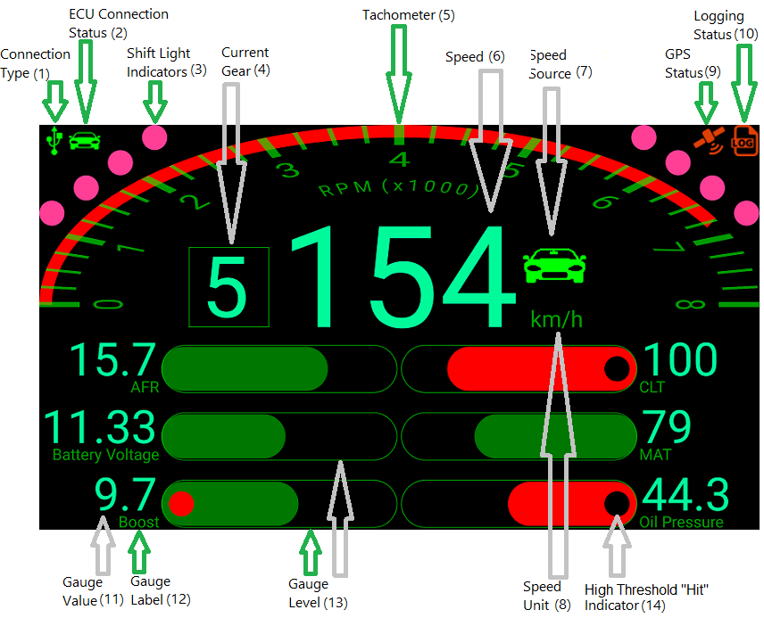
Just published my paid Android Megasquirt MSTrackIt App and free MSTrackIt_Demo App on the Google PlayStore.

Image

I've tested them on an MS3 and they SHOULD run on an MS2 but I can't confirm that yet.
The Apps don't support Bluetooth yet (waiting on a Bluetooth Serial dongle from DIY Autotune) but do support the USB and serial interfaces (FTDI USB-Serial cable/adapter is required for the serial interface; USB OTG cable/adapter is required if the Android device has a USB2.0 jack).

The only difference between the paid and free Apps is that when the ECU is connected, gauges are only updated at 5 second intervals and the data is logged at 100x the specified rate.
The Demo version is intended to allow users to evaluate the App before purchasing it.

The Android Apps can be found on the Google PlayStore (https://play.google.com/store/apps/details?id=com.lokiel.mstrackit and https://play.google.com/store/apps/details?id=com.lokiel.mstrackit_demo).

A QuickStart Guide and comprehensive User's Guide can be found at http://lokiel.weebly.com/android-mstrackit-app.html.


Originally posted by bruce, Fri Apr 21, 2017 12:24 pm[

You're an App Developer now. Good stuff!
If only I could figure out Arduino...


Originally posted by Lokiel, Fri Apr 21, 2017 1:39 pm[

^
I'm a software engineer (aka. "programmer") by trade and also wrote the Adaptronic AdapTrackIt App a few years ago.

These Apps were a great way to learn how to write Android Apps since they're quite complex so allowed me to exercise many of the Android features (they're not just "noddy" "Hello World" Apps).


Originally posted by TCR, Wed Apr 26, 2017 12:41 pm[

Great job. I will need to look into this when I get my car back with the MS3 installed.
Don't worry about dying, worry about not living!
Garage Thread: http://www.mx5cartalk.com/forum/viewtopic.php?f=57&t=76716

User avatar
Lokiel
Forum legend
Posts: 4126
Joined: Thu May 28, 2009 2:39 pm
Vehicle: NB SE
Location: Brisbania

Re: Lokiel's "Gina" (once a 2004 Titanium SE) Recreated AGAIN

Postby Lokiel » Tue Jun 05, 2018 8:38 pm

Originally posted by Lokiel, Sun Sep 24, 2017 5:44 pm

Originally posted by Lokiel, Sat Apr 29, 2017 11:48 pm[

I finished up the wiring of the SPAL fan today so thought I'd post my setup for other MSM/SE owners to use as a reference.

MSM/SEs have 2x 2-speed fans rather than the normal 2x 1-speed fans of other NBs.
They also have 3 relays to control the fans, whether they're off,high-speed or low-speed; normal NBs only have 2 relays.

I did a lot of reading of the MSM wiring diagrams and the old mazda-speed.com site and MT.net regarding how to wire up the fan and configure it in TunerStudio and the best advice I found was to "ignore what anyone else has done and configure what works for you!".

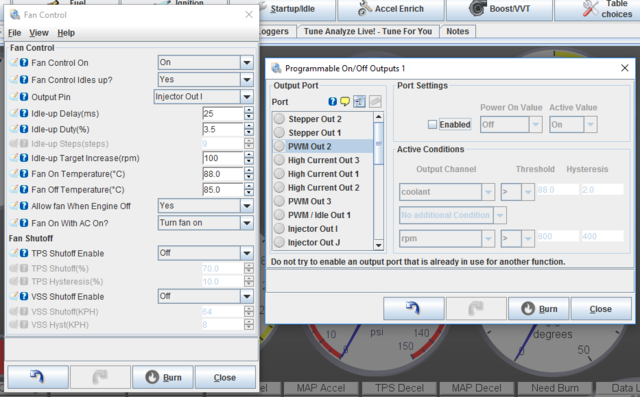
Since I now only have one fan I can simply control the fan from TunerStudio's BasicSettings->FanControl menu and disable the other two fan controllers in the AdvancedEngine->Programmable Outputs menu:
Image

Notes:
* TPS and VSS Shutoff were disabled in the Fan Control menu
* PWM Out 2 and High Current Out 1 were disabled in the Programmable Outputs menu (these were introduced to TunerStudio to allow staged-fan control startup; starting the two fans at separate times reduces the alternator impact of starting the fans at the same time)

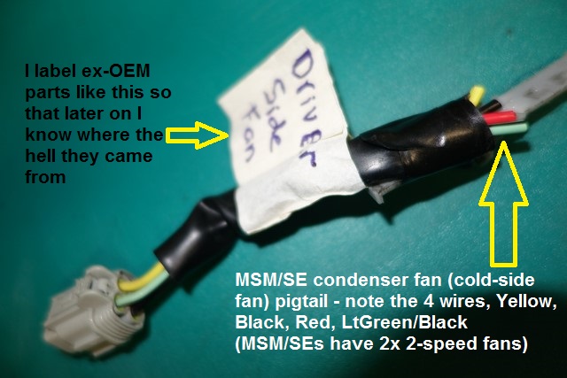
Now I had to figure out what combination of fan wires to use:
Image

Connecting the LightGreen/BlackStripe wire to the SPAL fan's Red wire and the OEM Black wire to the SPAL fan's black wire worked (I temporarily connected these and played around with the Fan On/Off temperatures around room temperature to verify this).
- the unused Red and Yellow wires were taped-off and tucked back into the OEM harness' rubber sheath.

I've got some waterproof 2-pin connectors that I was going to use but they're only rated to 20Amps so I needed to stick with the SPAL fan's blade connectors.

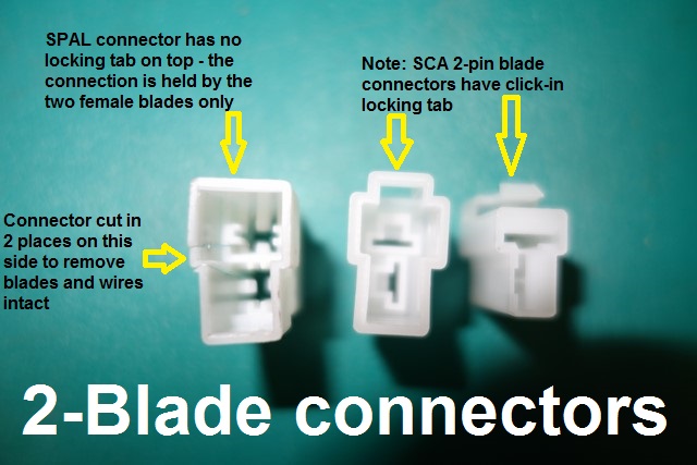
I mentioned in a previous post that I wasn't impressed with the SPAL fan's male 2-blade connector since it's not waterproof - I have another gripe with it:
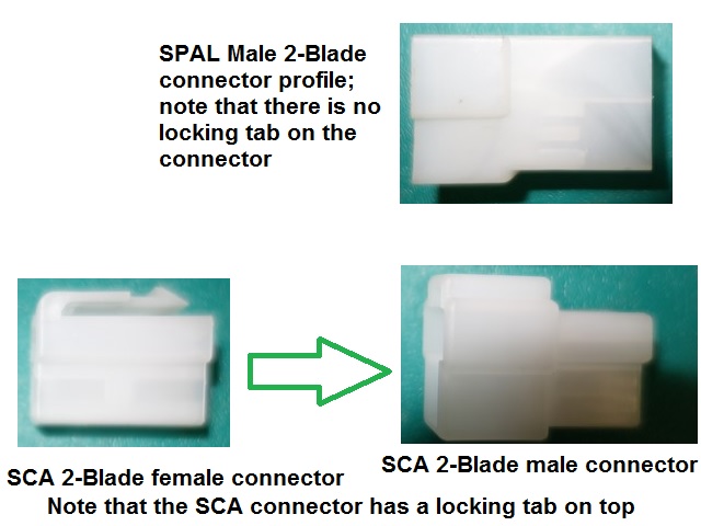
I've used SCA blade connectors in the past and their connectors have a click-lock connector on the top.
The SPAL male connector didn't have this so is only held by the two female blade connectors - not as secure as the SCA connector.
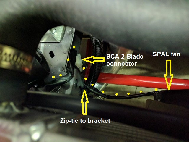
Since I needed a female 2-blade connector for the SPAL 2-blade male connector and I had some SCA 2-blade connectors, I cut the SPAL connector to get the male blades out and used the SCA male and female connectors - much better!
Image

Image


I used the condenser fan (coldside fan) harness since there's more room on that side (if I flipped the fan 180* I could've used the other fan but that side's more crowded with the A/C plumbing):
Image

- the yellow dots highlight the routing of the SPAL fan's wiring.

Rather than eliminating the unused hotside fan's wiring, I decided to tuck it away out of sight in the cold air box by folding it 3 times to finish the job off.
I chose a short re-usable plastic tie that was just big enough to tie the fan wiring to an existing harness wire in the cold air box.
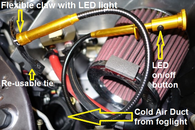
Then the [b]WORST[/b] possible thing that could happen in that situation occurred - I dropped the tie which went straight down the cold air duct and lodged against the foglight grille.
Much swearing ensued since I was so close to finishing the job and I really didn't want to have to pull the duct off to get the tie. At least the car was still on ramps!
I grabbed some wire, put a hook on it and tried to fish it out with no success, then remembered the "freebie" flexi-claw with LED tool I got with my drill press:
Image

- this tool is awesome, I could look into the foglight duct and see the tie with the LED and work the claw in position to grab it; only took two attempts!


Originally posted by ManiacLachy, Sun Apr 30, 2017 3:46 pm[

If I ever buy a TSE Crossflow, I'm coming over to your place for the install! Great work, as usual.
Don't worry about dying, worry about not living!
Garage Thread: http://www.mx5cartalk.com/forum/viewtopic.php?f=57&t=76716

User avatar
Lokiel
Forum legend
Posts: 4126
Joined: Thu May 28, 2009 2:39 pm
Vehicle: NB SE
Location: Brisbania

Re: Lokiel's "Gina" (once a 2004 Titanium SE) Recreated AGAIN

Postby Lokiel » Tue Jun 05, 2018 8:39 pm

Originally posted by Lokiel, Sun Sep 24, 2017 5:46 pm

OK, that's ALL the original posts copied into this new thread, now I can start posting some of the updates I've done since [b]PhuckUBucket [/b]decided to pull their extortion stunt!


Originally posted by KevGoat, Sun Sep 24, 2017 6:06 pm

WOW!! Well done! Massive effort. Great to see it all back together.


Originally posted by ManiacLachy, Sun Sep 24, 2017 6:06 pm

Image


Originally posted by Lokiel, Sun Sep 24, 2017 7:34 pm

This was a lot of effort and if anyone else wants to do the same because they use (or used to use) PhotoBucket, I can assist them.

Here's the steps:

1. PM me with the MX5CarTalk thread you want to re-create
2. I'll auto-generate a list of all the PhotoBucket images in that thread and send you a 2-column spreadsheet of the result (first column will be all the PhotoBucket image addresses in the thread, 2nd will be blank - more on this in the next 2 steps)

Do these 2 steps together:

3. Copy your PhotoBucket images to your new image-hosting site (I use postimages.org but imgur or flickr are other alternatives - unfortunately Google wont do 3rd-party hosting at this time)
4. Fill in the second column of the spreadsheet with corresponding new image address

5. e-mail me the updated spreadsheet
6. I'll run a Python script using this spreadsheet to generate a new text file that contains the new forum text and e-mail it back to you
7. Create your new thread
8. To populate the thread, manually create new posts and cut&paste sections of the text file into each new post.
* I cut&pasted multiple posts into single new posts because it was way too much effort to create a "1-for-1" posting
* I tried to group related sequential posts together (eg. responses to my modz)
* There is a limit to how much text can be pasted into a post so you can't simply put the entire file into a single post
* Curiously there's a "smilie limit" of 10 per post so sometimes you won't be able to combine as many posts into one as you'd like (in this thread there are quite a few short "smartarse smilie posts" in a row so I had to group these one-liners into several posts rather than one - all in good fun so keep it up)

Steps 3 ,4 and 8 do take time but it's worth doing to save your thread.

I had over 1,000 images in PhotoBucket :(


Originally posted by 93_Clubman, Mon Sep 25, 2017 10:53 am

Nicely re-Ginarated!


Originally posted by Lokiel, Mon Sep 25, 2017 12:34 pm

FYI regarding the links to the original thread posts:

I created a new thread from the original thread and for each post included a link to the original post so that the original post could be seen/verified.

After a few PMs between Okibi and myself regarding making the original thread "read-only", the two threads were actually merged which eliminates duplication. Unfortunately this basically threw away all the original posts so the links to the original post are no longer valid (ie. if you click on them, they will no longer show the original post) :(
Don't worry about dying, worry about not living!
Garage Thread: http://www.mx5cartalk.com/forum/viewtopic.php?f=57&t=76716

User avatar
Lokiel
Forum legend
Posts: 4126
Joined: Thu May 28, 2009 2:39 pm
Vehicle: NB SE
Location: Brisbania

Re: Lokiel's "Gina" (once a 2004 Titanium SE) Recreated AGAIN

Postby Lokiel » Tue Jun 05, 2018 8:40 pm

Originally posted by Lokiel, Mon Sep 25, 2017 9:19 pm

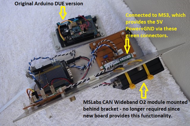
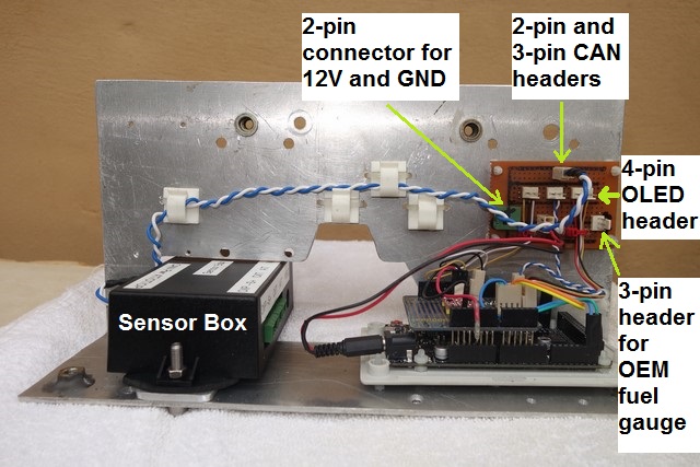
One of the projects I've been working on since PhuckU-Bucket started holding my images for ransom has been the Arduino configuration I use to display MS3Pro data on my twin multi-line OLEDs in the instrument cluster.

My original Arduino was a DUE that required a 5V->3.3V module for the analog signals since the DUE can only handle 3.3V analog inputs (I used one for the fuel gauge, leaving only one free 5V->3.3V input on the converter module.)
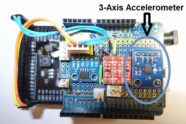
Image
Image
* The small blue daughter-board on the top left is a CAN transceiver
* The small red daughter-board in the top middle is the the 5V<->3.3V converter
* The small blue daughter-board on the top right is a 3-Axis gyro

The MS3Pro has inputs for AIT and I've configured its two other analog inputs for Oil Pressure and Oil Temperature.

My goal was always to add more analog inputs for additional temperature and pressure sensors (I'm interested in seeing fuel pressure and the temperature difference in the engine bay the Cold Air Box makes and if insulation will help).

I used an Arduino UNO (designed for 5V analog inputs), CAN Shield and DIY shield to replicate my original configuration:
Image
This configuration worked as well as my original setup but I had to "mangle" the code to avoid the UNO "register overflow" compilation error (this is a known compiler issue for the board when code starts getting larger).
Unfortunately no amount of code mangling allowed me to add additional sensors without getting the "register overflow" compilation error so I decided to switch to another Arduino version (different CPU).

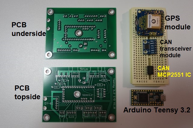
I chose the Arduino Teensy 3.2, a very small Arduino with a lot of I/O ports and memory and a CPU with plenty of grunt.
It didn't take long to realise that wiring was going to be a big issue, prototyping on a breadboard produced a rat's nest of wires that were a pain to figure out when one of them came loose.

I decided to "take it to the next level" and design my own PCB, something I'd never done before.

After playing around with a few PCB tools I settled on PCB Express, it's probably the easiest tool for beginners and perfect for my simple needs.

I started wanting only 1 analog sensor for fuel level, a single push-button for OLED control, 2 temperature sensors, 1 pressure sensor, CANbus I/O and OLED I/O so a 2-layer board seemed appropriate (and cheaper to manufacture).

I planned on using the same CANbus I/O daughter-board as I'd used previously until I realised that it only had 2 resistors on it and an IC for the CAN transceiver. The daughter-board takes a lot of space so I decided to eliminate it and mount the individual components on my board instead.

After adding everything I wanted initially there was still plenty of Teensy analog and digital I/O ports available so I figured I may as well use them since it wasn't going to cost me any more in manufacturing.

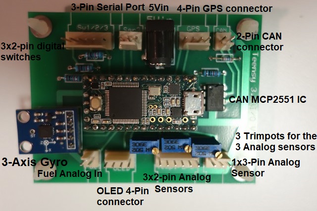
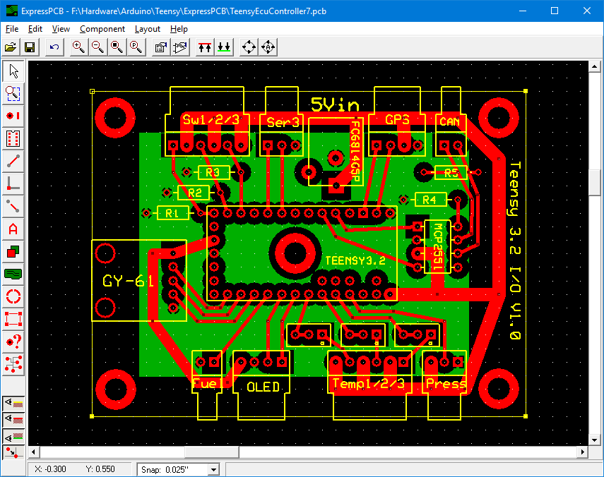
I added a 4-pin connector for GPS input (I've written and tested code for this), an additional analog temperature sensor, 2 additional digital pushbuttons (to allow selection of "[b]Ludicrous Speed[/b]"), a 3-Axis gyro (using the same daughter-board as I used earlier) and a serial connector that will be used for Innovate's Wideband O2 Serial input, allowing me to get rid of the MSLabs CANbus module (writing code for that is my next job).

Here's the ExpressPCB design:
Image
- way more complex than I initially planned for!

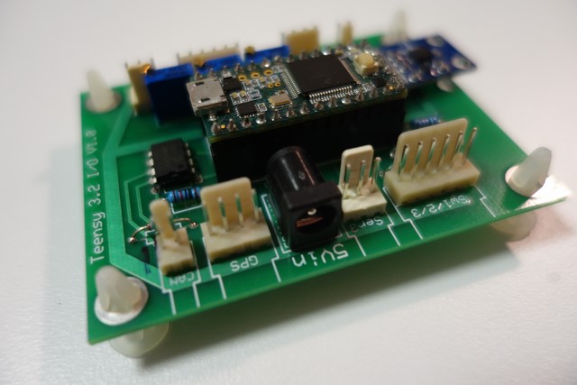
I sent the design file off to ExpressPCB in the US and a week later 4 boards, the minimum for a specific sized-board, turned up:
Image
- I must admit that when I saw these, I actually impressed myself!

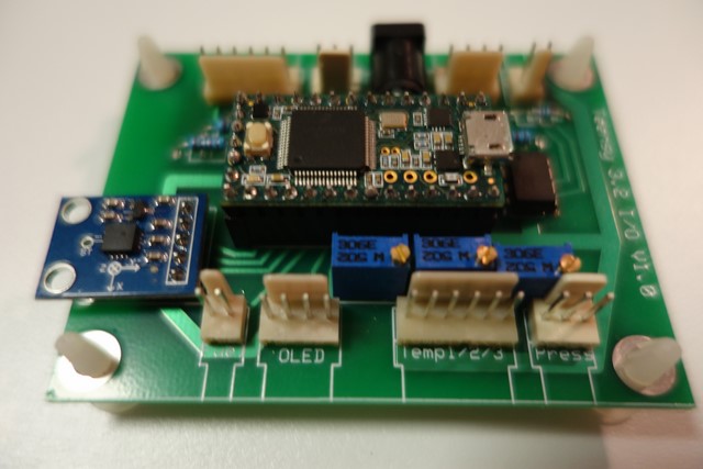
It's easy to screw up but electronically I managed to get it right so I then spent the evening populating the board:
Image
- getting really good at soldering now (ignore the crooked 3-axis Gyro daughter-board, I bent one of the pins to hold it in when soldering and didn't realise it made it crooked until it was too late)

I designed the board to use 90* pin connectors so that the wires can lie flat on a surface but since this board is my first prototype, I used vertical pin connectors because it's easier to benchtest (takes up less bench/table space).

I was concerned that I'd get the hole spacing on my board and the gyro daughter-board wrong - I was half right, the width was perfect but the depth wasn't so it wont be bolted to the main board. It's held solidly by the 6 soldered pins so it's no biggie (but still bugs me).

Image
Image
FYI: The 5Vin port will be used to power the Arduino in the car - if the USB port was used, it wouldn't take long for vibration to sheer it from the Arduino board.

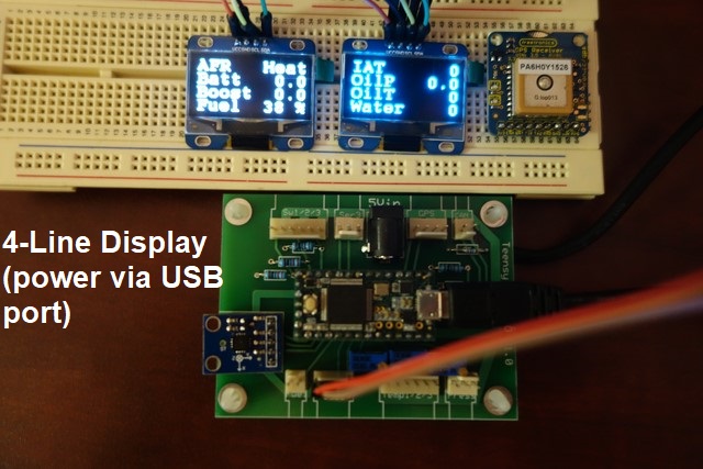
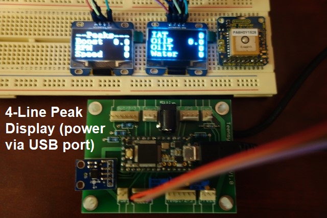
Some crappy bench shots showing the 3 modes of the Twin OLEDs:
Image
Image
Image

The ultimate test was hooking the board's 2-pin CANbus connector up to the MS3Pro's CANbus and seeing the data being updated!

This board replaces the two earlier right hand side boards and could replace all 3 boards I used earlier.
I plan to keep the left board since it already has the MS3Pro CAN, AIT, Oil Temperature and Oil Pressure connections.

My original glovebox gauge fascia was designed to "clear" the multi-level Arduino CAN shield "stack" and always looked odd to me so I'll probably re-do that now!
Image


Originally posted by speed, Tue Sep 26, 2017 9:21 am

Great job recreating your thread! I may take you up on your offer and pm you. Fortunately I retained most of my pics as I had switched to tapatalk a while ago but it would be good to get the earlier pics back.

The stuff you are doing with arduino simply amazes me.
So much custom goodness :)


Sent from my SM-A520F using Tapatalk


Originally posted by Lokiel, Tue Sep 26, 2017 11:25 am

There are SO many potential uses of the Arduino, I have plenty of projects I'd like to do with them but just don't have the time.

i learned a long time ago that you should only ever be doing 3 projects at any one time otherwise you never complete any of them:
1. The project that's almost finished and you're waiting for something
2. The project you're currently working on
3. The project you're planning next (research and part ordering in progress)

speed wrote:Great job recreating your thread! I may take you up on your offer and pm you. Fortunately I retained most of my pics as I had switched to tapatalk a while ago but it would be good to get the earlier pics back.
:

It doesn't take me long to do "my bits" since it's just a matter of running a couple of Python scripts so no worries there.

I'd prefer not to send users these Python scripts for a few reasons:
1. You need to install Python on your machine and I don't want to deal with questions regarding how to install and run Python
2. If there's an error in the scripts or some case I haven't handled properly I can quickly fix it
3. One of the scripts "scrapes" the mx5cartalk website for data so could be modified for malicious purposes (eg. accumulating data on forum members or copying the forum to another site)

You can download your own photos from PB if you login to your PB account.
It's quite painful due to the volume of pop-ups and advertisng the site has but you can download each album as a .zip file, then copy the images to another image-hosting site.
If you do have the original images available, it'll be far quicker to copy them to the new image hosting site because PB is incredibly slow and was constantly hanging all browsers I tried - it took me a week to download all my albums as zip files since I had a lot of albums.


Originally posted by greenMachine, Tue Sep 26, 2017 10:00 pm

speed wrote:Great job recreating your thread!


I'll second that.

I hang out on a few forums, and one thing that hisses me off big time is the number of photos that 'disappear'. The 'bucket debacle has just made things infinitely worse.

So I am sure Speed and I speak for many in thanking you for your great work! :NETPOINTZ:

:mrgreen:
Don't worry about dying, worry about not living!
Garage Thread: http://www.mx5cartalk.com/forum/viewtopic.php?f=57&t=76716

User avatar
Lokiel
Forum legend
Posts: 4126
Joined: Thu May 28, 2009 2:39 pm
Vehicle: NB SE
Location: Brisbania

Re: Lokiel's "Gina" (once a 2004 Titanium SE) Recreated AGAIN

Postby Lokiel » Tue Jun 05, 2018 8:41 pm

Originally posted by Lokiel, Sun Feb 04, 2018 7:50 pm

It's been a while since I updated my garage thread, mostly because I'm in the middle of my Arduino MegaSquirt project and it's been too damn hot & humid to work on the car in summer.

Originally I was planning to get my TSE kit installed by someone who knew what they were doing and because my NitroDann 3" exhaust needs to be modified and I've never welded anything in my life other than JB welds and plastic welding.

I budgeted around A$4-5,000 for this including the tune because I've got a few custom-modz I want (eg. mixing manifold mod to make radiator hose routing simpler) and the need to fabricate hotside intercooler plumbing) and it's always safer to over-budget.

I've had a few big expenses and made some purchases I just couldn't pass up so the TSE install just kept getting delayed.
My New Years resolution is "No more spending until the TSE kit is installed!".

ManiacLachy suggested I should do the install myself and either tow the car to an exhaust shop to complete the exhaust or fit a dodgy one and drive it there.
I hadn't even thought of that as an option and PROBABLY can fit the TSE kit myself - I've got all the components and I bet 99% of the tools needed (that 1% I'm missing will really bite me in the arse I'm betting).

It'll certainly halve the cost and I'll end up with the install I want so I'm going to attempt it AFTER I've completed my Arduino MegaSquirt project - I learned a long time ago that I can't work simultaneously on multiple projects (unless one is delayed because I'm waiting on parts/information), they take twice as long and sometimes never get completed.

My Arduino MegaSquirt project began as a means of allowing the MegSquirt to receive more input signals and be able to display multiple sensor data on 2 OLEDs which are mounted in the instrument cluster's Fuel Level gauge and Dummy Coolant gauge.

The MS3 has 2 spare generic input signals and I used them for Oil Temperature and Oil Pressure but I wanted more, Fuel Pressure, additional temperature sensors (so that I can monitor temperatures inside and outside my Cold Air Box to determine if it needs additional insulation) and I also wanted to add GPS and Accelerometer inputs so that all track data can by synched and logged in one place (by the MS).

Originally I used an Arduino DUE since I already had one and knew that it had plenty of grunt, memory, inputs and sort-of supported CAN (an additional CAN transceiver is needed).

The Arduino DUE turned out to be a really bad choice though because it only supports 3.3V input signals so every 5V input signal needed to be converted to a 3.3V signal. I used a daughter card that supported conversion of 2 signals to achieve this and wasn't happy with it - it made the project more expensive and complicated than it needed to be.

I switched to an Arduino UNO, not as powerful, less memory but can handle 5V input signals.
The UNO needs a CANbus shield since it doesn't support CAN on board and I used another expansion shield on top of that for extra components needed.
I quickly ran out of program memory for everything I needed and encountered a known issue with the UNO compiler (I ran out of registers; as others have done to work around this problem, I re-ordered parts of the code to fix this).
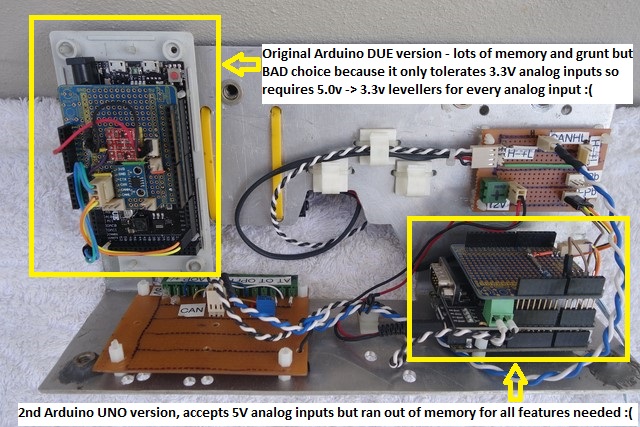
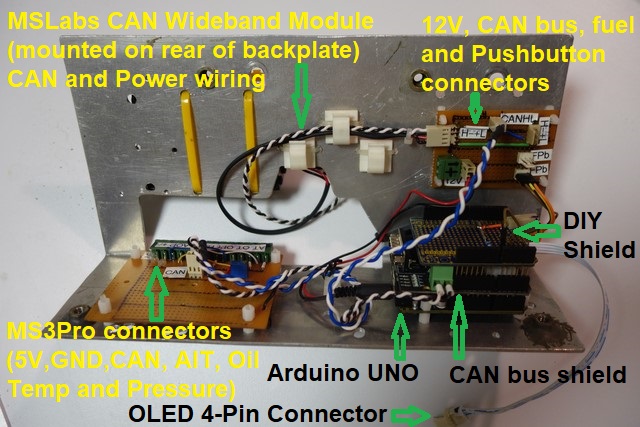
Image
Image
Image

The next Arduino step up was the Teensy 3.2 which required me to create my first ever PCB.
After playing around with a lot of tools, I chose ExpressPCB, it's free (because they manufacture your board) and is very easy to use for a beginner.

I also added support for the Innovate Wideband O2 sensor so that I can get rid of the MSLabs Wideband O2 controller - it takes up too much space and requires additional wiring.

I designed the board as small as I could, so that it's easier to mount anywhere, and with multiple connectors, mostly one per component. Using multiple connectors meant that I only needed a 2-layer PCB which I thought was great because it made the board cheaper.
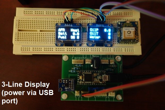
Image

I installed the board in Gina using the existing aluminium bracket shown in the earlier photos but wasn't happy with all the connectors, they made for a real rats nest.

As part of the testing, I found that MegaSquirt's TunerStudio wasn't reporting the Latitude correctly. See http://www.msextra.com/forums/viewtopic%20...%2031&t=67777 for details of this.
The short story is that they've NEVER tested GPS in the Southern hemisphere before so the way they encode/decode the Latitude is wrong.
It will be fixed in the next MS3 firmware release.

After looking on the web for single connectors, I ordered one that I thought looked rugged enough and re-designed/ordered the PCB to use it. The connector had 36 pins but I only needed 34 so I simply cut two of them off.

With a single connector, the traces to the pins got more complicated so I needed to create it as a 4-Layer board, to prevent trace overlaps, which increased the cost of the board.
After reading ExpressPCB's pricing policy, I saw that by using their standard-sized board (rather than the custom-sized board I created earlier) that the cost of the board was halved.
This worked out quite well because the connector I chose required the board to be about that size anyway.

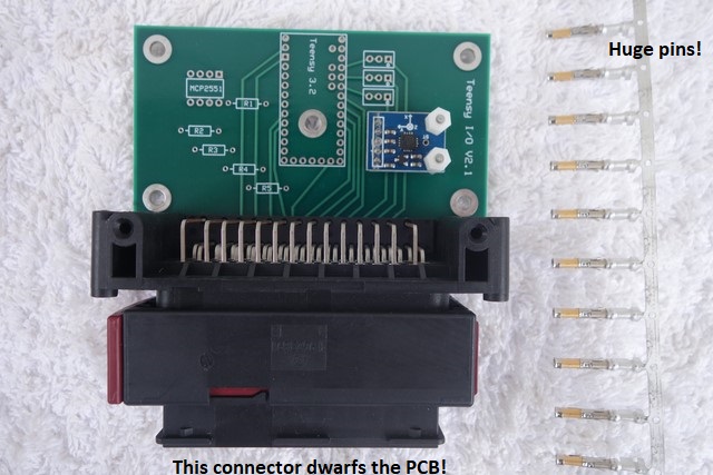
After receiving the PCB and connector, I realised several things:

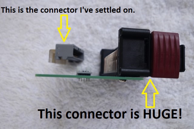
1. The connector is HUGE!
2. The bottom row of connector pins to the PCB are very tight - soldering needs to be very precise.
3. The connector plug pins are huge, probably way too big for the sensor wires I need.
4. Separating the connector's plug and socket will be difficult when it's mounted out of sight. The maroon tab needs to be pulled outward which moves the plug back and out of the socket. That's difficult to do and there needs to be space to do this. (FYI: I didn't choose this connector just because it has Queensland's maroon in it).
5. The connector is very expensive.
6. I couldn't find a case for this combination that I was happy with.
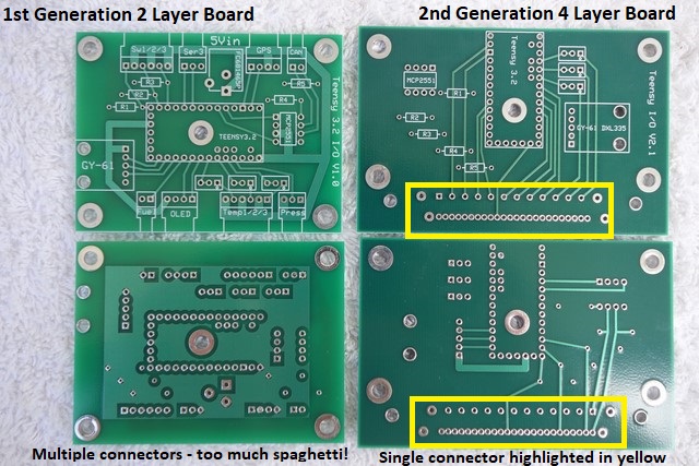
Image
Image
Image
Notes:
* It doesn't look like it in the above shot due to perspective, but the PCB is actually wider than the connector.
* This time I got the Accelerometer daughter board's mount holes correct, it now mounts to the PCB by theses points, not just by the daughter-board's 6 pins.

So I learned 2 things from that experience:
1. Start the design based on the case that will be used.
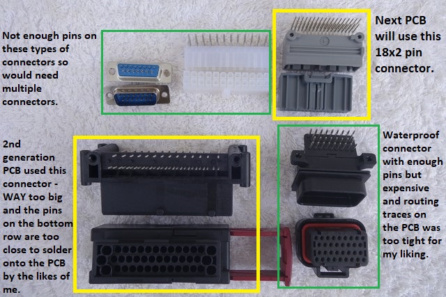
2. Choose a connector that will fit the case, be rugged enough, easy to plug/unplug, be easy enough to solder to the PCB and have the correct sized plug pins that can be crimped to the required wire.

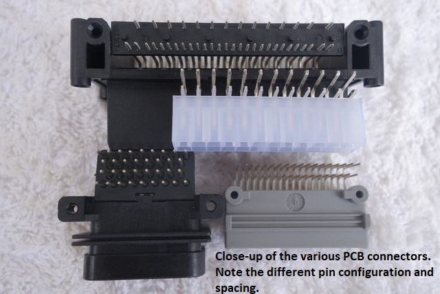
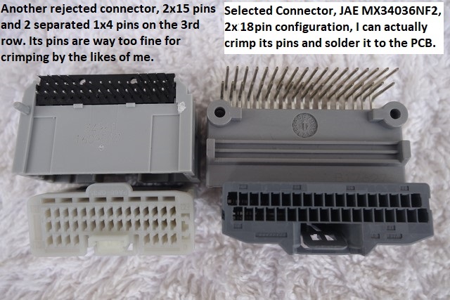
I ordered a sh**tload of different connectors and their pins so that I could determine which was most suitable (must be small but not so small that the PCB pins are un-solderable or plug pins are too small for the wire needed):
Image
Image
Image

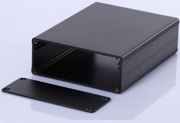
Next I ordered 4x 72Wx80Lx29H mm extruded aluminium cases that I knew I could fit my next PCB into:
Image
The above photo has the case upside-down - the two channels at the top should be on the bottom - the PCB slides into it so no mounting pins are needed in the PCB.
Unfortunately this is coming from China and is going to take forever - they don't have any express shipping options (they're cheap though, 1/5 the cost of anything available in Australia).

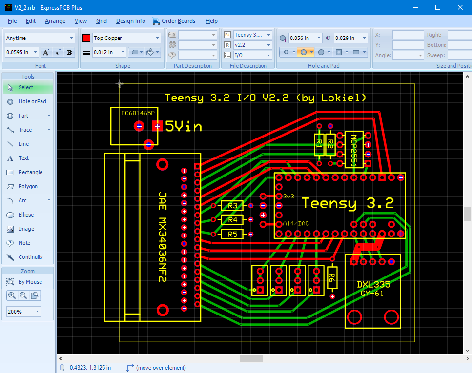
After all the different connectors arrived, I chose the one whose pins I knew that the "average Joe" could crimp and could solder to the PCB, re-designed the PCB to fit the case and ordered 4 PCBs yesterday (one for each case I ordered).
Image
Note: Since I now had the extra PCB width, I decided to provide 5V power and GND via a separate barrel connector - most manufactures do this and it allows thicket gauge wire to be used than on the main connector.
This freed up a couple of pins on the connector and since I had more space on the PCB, I added another temperature sensor and accompanying TrimPot.

This version of the board supports:
* 4x Temperature sensors
* 2x Pressure sensors
* 1x Fuel Level sensor
* 1x Innovate Wideband O2 serial input
* 1x Serial GPS input
* 1x CANbus
* 1x in-built Accelerometer
* 1x OLED output (supports up to 2 OLEDs)
* 3x Digital Inputs (one used to control OLED displays)

Now I just need to wait for everything to arrive, design 3-D printed gauge pods for the OLEDs and write the manual.

I've enlisted ManiacLachy as my independent beta-tester for this project.


Originally posted by Magpie, Sun Feb 04, 2018 7:59 pm

Looking forward to seeing Gina out Purga way before the end of 2018 :)
Don't worry about dying, worry about not living!
Garage Thread: http://www.mx5cartalk.com/forum/viewtopic.php?f=57&t=76716

User avatar
Lokiel
Forum legend
Posts: 4126
Joined: Thu May 28, 2009 2:39 pm
Vehicle: NB SE
Location: Brisbania

Re: Lokiel's "Gina" (once a 2004 Titanium SE) Recreated AGAIN

Postby Lokiel » Tue Jun 05, 2018 8:41 pm

Originally posted by Cus, Sun Feb 04, 2018 9:08 pm
How do you find the teensy compared to the arduino?


Originally posted by Lokiel, Sun Feb 04, 2018 9:57 pm
Cus wrote:How do you find the teensy compared to the arduino?

The Teensy 3.2 is essentially just another Arduino version, it has plenty of grunt and memory to handle whatever you'll need to do with it, all the I/O of a regular Arduino UNO plus multiple serial ports and pseudo CANbus support (you still need the CAN transceiver).

You can use the regular Arduino IDE and compiler once you've installed the Teensy Board in the Board Manager.

The Teensy doesn't have compiler issues like the UNO (running out of registers) since it's a different CPU.

You'll need to use Teensy-specific libraries though (eg. the CAN and GPS libraries are different to the regular Arduino libraries) since the CPU and architecture is different.

The Teensy 3.5 and 3.6 are longer with more pins and features, have an on-board SD memory card, on-board clock, more memory and faster CPUs.

If you've used another Arduino, the Teensy isn't much different.

If you're not into soldering though then give it a miss - they come with no pins pre-soldered so you'll need to spend the time soldering them in.


Originally posted by ManiacLachy, Mon Feb 05, 2018 7:56 am

This is a lot of work, but it's an awesome product. Really useful for anyone running a Megasquirt, which is most boosted MX-5s/Miatas and plenty of other makes in the US. It's a little DIY, but that's perfect for you MS demographic.

I can't wait to get it set up and testing. I'm going to need to order a few sensors soon I think.


Originally posted by Magpie, Mon Feb 05, 2018 10:26 am
ManiacLachy wrote:I'm going to need to order a few sensors soon I think.
Now you are talking!
Don't worry about dying, worry about not living!
Garage Thread: http://www.mx5cartalk.com/forum/viewtopic.php?f=57&t=76716

User avatar
Lokiel
Forum legend
Posts: 4126
Joined: Thu May 28, 2009 2:39 pm
Vehicle: NB SE
Location: Brisbania

Re: Lokiel's "Gina" (once a 2004 Titanium SE) Recreated AGAIN

Postby Lokiel » Tue Jun 05, 2018 8:42 pm

Originally posted by Lokiel, Tue Feb 13, 2018 12:49 pm

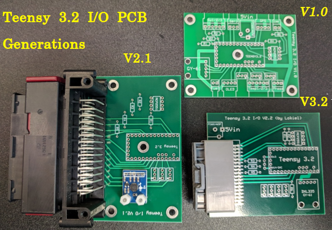
New PCBs (V3.2) arrived today - here's all the generations so far:

Image
* V1.0 is a 2-layer board, has lots of individual connectors for each component and turned into a rats nest
* V2.1 is a 4-layer board, has a MASSIVE single connector and finding a case for it wasn't easy
* V3.2 is a 4-layer board, has a smaller connector, a separate Power+GND connector and was designed to slide into an aluminium extruded metal case. The visible traces are the ones shown in red in the earlier ExpressPCB screenshot; the ones shown in green are on the underside of the board.

As always, I was praying that I'd got the connector pins correct on the PCB - if they mis-aligned, the board can only be used by soldering wires directly to the board.
I spent an entire evening with the connector's schematic and adding it to ExpressPCB, quadruple checking everything to ensure that it was correct.

I guess after work for the rest of this week I'll be soldering on all the components and connecting all the pins to test it on the weekend - tedious tasks best done in small bursts.

No idea when the aluminium extruded cases will arrive from China - they gave about a month window of delivery :(


Originally posted by ManiacLachy, Tue Feb 13, 2018 1:28 pm

I like the visual evolution of the boards. From small and complicated, to large and simplified (but certainly not simple), to small and simplified.

Very cool work. :beer:


Originally posted by Lokiel, Tue Feb 13, 2018 2:44 pm

The first board looks more complicated because it's a 2-layer board (cheaper to manufacture than a 3-layer board).
The bottom of the board is the ground plane and the top has all the other traces, including all the power traces.
I thought I'd make it as small as possible to make it easier to fit into a small box which would be easier to fit anywhere - this makes it look even more complicated.

For the next generation I thought I'd add a second pressure sensor since the first one only supported one (nice to have one for oil and one for fuel)).
This made it too hard to do on a 2-layer board since I couldn't avoid overlapping traces so I switched to a 4 layer board.
The middle 2 layers are 5V power and GND layers and the top and bottom layers are available for all other traces.
I used their standard sized board, which actually made the cost about half of the 2-layer board which was a custom size, since the connector required a board of that approximate size anyway.

Now the top layer only has 1/3 of the original board's traces on it, the rest have moved to the 5V layer and bottom layer so routing is much easier, the original board's traces have been split across 3 layers.

Development has been interesting/educational and I was told it usually takes at least 3 versions to get right (or close to it) since you can't think of everything. I should have waited for the 2nd board's connector to arrive before designing and manufacturing the board because once I had the connector in my hand I realised it was way too big - I'm just not patient enough at times.

This started out as a simple project, to output MS3 data on OLED gauges but left out the I/O capabilities of the Arduino so I kept adding features until now, when all the Analog inputs have been used, as well as 2 of the Teensy 3.2's Serial ports to support GPS and the Innovate Wideband O2 serial format.

Getting close to my final goal now, all this in one tiny box with a single harness to connect (and one 5v + GND barrel terminal)
Don't worry about dying, worry about not living!
Garage Thread: http://www.mx5cartalk.com/forum/viewtopic.php?f=57&t=76716

User avatar
Lokiel
Forum legend
Posts: 4126
Joined: Thu May 28, 2009 2:39 pm
Vehicle: NB SE
Location: Brisbania

Re: Lokiel's "Gina" (once a 2004 Titanium SE) Recreated AGAIN

Postby Lokiel » Tue Jun 05, 2018 8:42 pm

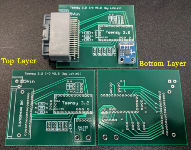
Originally posted by Lokiel, Tue Feb 13, 2018 3:58 pm

Top & Bottom layers:
Image


Originally posted by Lokiel, Sun Feb 25, 2018 8:24 pm

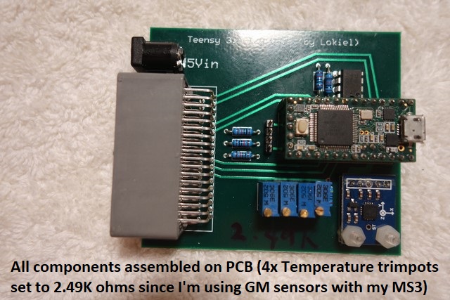
Teensy 3.2 I/O PCB components were soldered onto one of the boards during the week, the 4x temperature pull-up trimpots configured to 2.49K ohms (I'm using GM temperature sensors since the MS3 already has calibration tables configured for these and require a 2.49k ohm pull-up resistor) and all connections tested.
Image

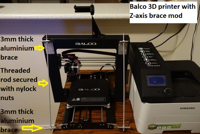
Also during the week, I FINALLY unpacked my Balco 3D printer (needed to make the OLED gauge housings), assembled it and did some reading on what improvement modz are needed.
Once assembled, it's fairly obvious that the gantry isn't very stable and wobbles a LOT which will affect printing.
There's a "Z-axis brace" mod for this, you can buy the parts or 3D print the mounts but I figured I'd make my own out of 3mm thick aluminium and threaded rods which would be much more solid than any 3D printed mounts and I can actually pick up the unit by the gantry now:
Image
All braces were mounting using existing holes but I did have to replace all their screws since they were now 3mm too short :(
Threaded rods are needed to allow the Z-axis to be calibrated correctly with the printbed.

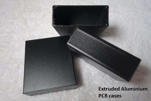
The extruded aluminium cases arrived Friday which was a surprise given that the expected delivery window from China was 2 months:
Image

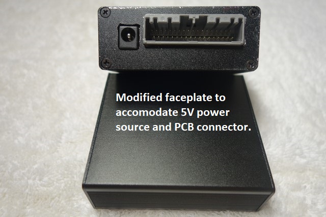
I put the 3D printing task on hold and modified the faceplates of one unit to accommodate the PCB's power and Arduino connectors:
Image
- a bit rough and I SHOULD have taped the faceplate to protect it during the cutting/filing - it's my test unit and will be used as a template for the other units which I'll take more care/time with.

I designed the board-size to fit in these specific cases but until I actually had the cases and the PCBs, I didn't know if I'd screwed up or not; thankfully they fitted perfectly.

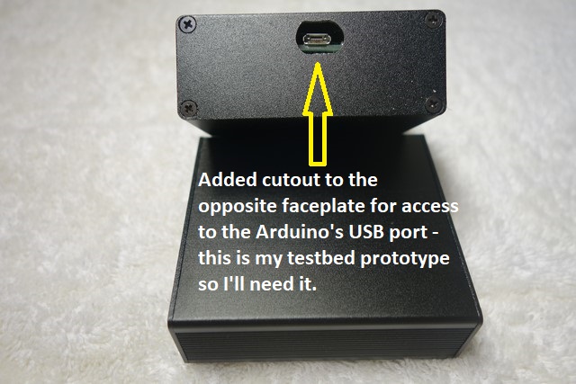
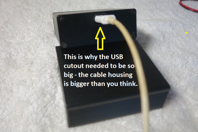
I also added an access slot for the Arduino's USB port since this will be my test unit and I'll want to tweak the code without the hassle of unscrewing the whole faceplate:
Image
Image
Production units wont have this cut-out.

I still need to find out how much current the unit will draw when fully populated.
The MS3 provides a stable 5V power output but the MS3 unit and any peripherals powered from its 5V source are limited to 500mA so I suspect I'll need a stable independent 5V source to power the unit.

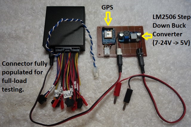
I fully-populated the PCB connector using 2-pin, 3-pin and 4-pin connectors which took a while since it required the crimping of 36 pins to wires (getting really good at this fiddly job now, only screwed up 2 pins despite having "man-hands").
Using these connectors makes bench testing easier since I can easily connect them to a breadboard and all modules/sensors/switches to the breadboard.
- on a vehicle, wires are pinned directly to the connector and users only need to connect the pins they need.

I also mounted a 24..7V->5V DC-DC step-down buck connector onto a separate board to be the separate stable 5V power supply if I need it, along with a 10Hz GPS module.
This GPS module has an antenna connector so I can mount this board anywhere and place the antenna where it needs to be for best reception.
I have another GPS module that doesn't have an antenna connector and seems to work OK but that unit must be mounted in an optimal receiving position.
Image

After this, I needed a break so will do the load test during the week now that everything is all set up.
Don't worry about dying, worry about not living!
Garage Thread: http://www.mx5cartalk.com/forum/viewtopic.php?f=57&t=76716

User avatar
Lokiel
Forum legend
Posts: 4126
Joined: Thu May 28, 2009 2:39 pm
Vehicle: NB SE
Location: Brisbania

Re: Lokiel's "Gina" (once a 2004 Titanium SE) Recreated AGAIN

Postby Lokiel » Tue Jun 05, 2018 8:43 pm

Originally posted by KevGoat, Sun Feb 25, 2018 10:13 pm

Ummm ... just ... wow!! Way beyond me, but riveting.

Sent from my SM-G930F using Tapatalk


Originally posted by Okibi, Sun Feb 25, 2018 10:32 pm

Yup same :mrgreen:


Originally posted by Magpie, Mon Feb 26, 2018 7:24 am

Load test in Gina on the road, in the sun ?


Originally posted by ManiacLachy, Mon Feb 26, 2018 8:11 am

Looking good. You'll need a cool name for you product's company. "Loki-Tech"? - nah, we can do better than that!


Originally posted by IanR, Mon Feb 26, 2018 7:23 pm

I'm slowly clapping with my mouth open, speechless. A new era of car modification is here.
Don't worry about dying, worry about not living!
Garage Thread: http://www.mx5cartalk.com/forum/viewtopic.php?f=57&t=76716

User avatar
Lokiel
Forum legend
Posts: 4126
Joined: Thu May 28, 2009 2:39 pm
Vehicle: NB SE
Location: Brisbania

Re: Lokiel's "Gina" (once a 2004 Titanium SE) Recreated AGAIN

Postby Lokiel » Tue Jun 05, 2018 8:43 pm

Originally posted by Lokiel, Thu Mar 01, 2018 10:22 pm

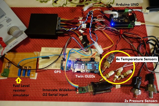
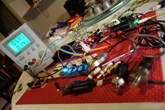
Load testing with all I/O connected: 1xGPS, 1xCAN, 1xInnovateWidebandO2, 1xOLED(supports 2 OLEDs), 4xTemperature sensors, 2xPressure sensors, 3xDigital switches (1 for control of OLEDs, 1x Fuel Level input.
An Arduino UNO was used to Tx/Rx CAN messages for the test:Image
Image
- boy am I glad I connected the test unit's pins to 2, 3 and 4 pin connectors depending on their function and labelled them, it makes identifying them MUCH easier rather than counting for them on the connector (2 rows of 18 pins).

Maximum current draw occasionally spiked at 0.15mA but I couldn't snap a photo of this, it was too quick.
Current draw hovered between 0.13mA and 0.14mA.
Connecting the external antenna will probably bump this a tad too so it looks like it would be safer NOT to use the MS3 as a 5V power source (0.15mA is 30% of the 500mA that the MS3 was designed for).


Originally posted by Magpie, Fri Mar 02, 2018 10:55 am

What is the logging rate?


Originally posted by Lokiel, Fri Mar 02, 2018 7:32 pm

Magpie wrote:What is the logging rate?

3ms intervals is the lowest MS rate for SD card logging.
CANbus baud rate is 500000bps.
GPS rate for this GPS board is in 10Hz.
Don't worry about dying, worry about not living!
Garage Thread: http://www.mx5cartalk.com/forum/viewtopic.php?f=57&t=76716

User avatar
Lokiel
Forum legend
Posts: 4126
Joined: Thu May 28, 2009 2:39 pm
Vehicle: NB SE
Location: Brisbania

Re: Lokiel's "Gina" (once a 2004 Titanium SE) Recreated AGAIN

Postby Lokiel » Tue Jun 05, 2018 8:44 pm

Originally posted by Lokiel, Thu Mar 22, 2018 10:06 pm

I thought I'd finalised my Arduino gauge/sensor box and posted it on MT.net where gooflophaze pointed out something I'd completely missed:

The Arduino Teensy 3.2's analog inputs are 5V tolerant, they're NOT true 5V inputs.

What this means is that any input voltage over 3.3v is simply treated as 3.3V.

In practice I'd never noticed this because the pressure and temperature gauges read as I expected and my fuel tank has always been about half full.

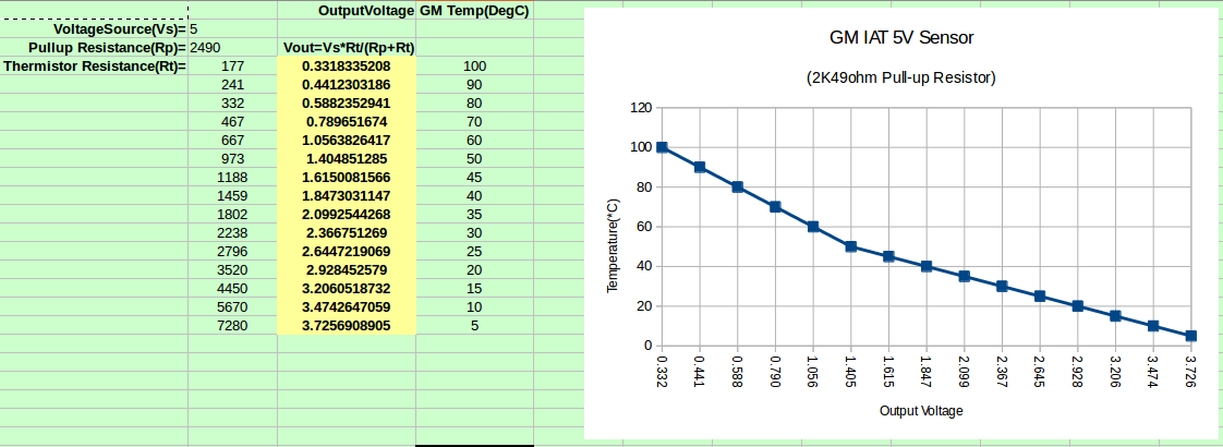
Plotting the GM's IAT voltage vs temperature graph using a 2,490ohm pull-up resistor shows that this is only an issue below 15*C:
Image
It hasn't been under 15*C here in Brisbane for a long time now so it's no wonder I missed it.

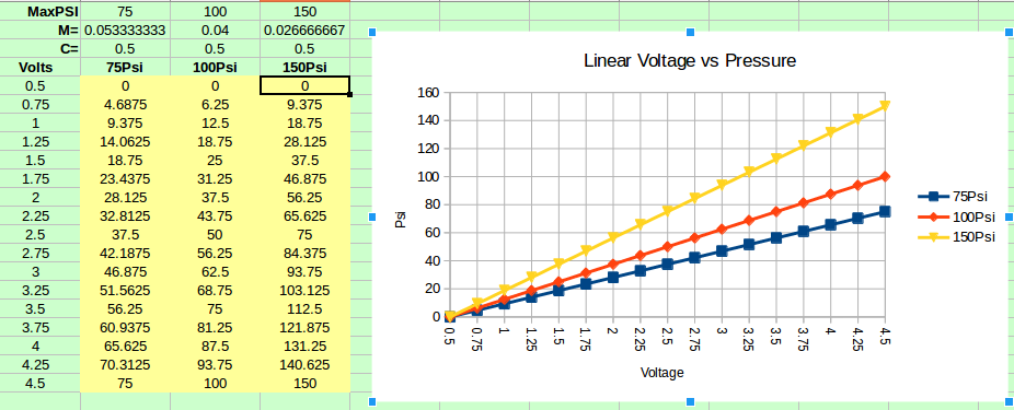
I have a 150psi Honeywell oil pressure sensor in the car so plotting Psi vs voltage (it's a linear range from 0.5-4.5V), I'd need to generate a pressure of over 103psi before this became an issue:
Image
Once again, no wonder I didn't see this issue.
If I had a 75psi sensor, it would be a problem over 51psi.
If I had a 100psi sensor, it would be a problem over 69psi.

I could have used a voltage divider to scale the analog inputs from 0-5V to 0-3.3V but this would drop the resolution of all sensors by 1/3, something I didn't want to do.

I decided to add an MCP3008 chip to the board.
This chip has true 5V analog inputs and outputs the data via an SPI interface, which is available on the Teensy 3.2 and wasn't being used.
The chip has 8 analog inputs but I only need 7 (4xtemperature, 2xpressure and 1xfuel) and don't have enough pins on the connector anyway for the unused analog input.
The chip's guide recommend the use of 1uF capacitors on each of the analog inputs to reduce noise so that's more crap I need to add :(

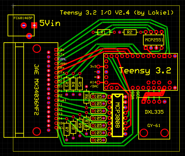
I redesigned the board to accommodate the MCP3008 chip and capacitors and, now that I've managed to find 2,490Ohm resistors as pull-ups for the temperature sensors, replaced the trimpots with simple resistors:
Image
Things started getting crowded and to route 3 of the MCP3008' pins to the Teensy's SPI pins, I needed to route them under the Teensy which means that two of the Teensy's analog pins cannot ne mated to the board - no biggie, I'm not using them anyway.

The boards arrived this week so I've spent the last 2 nights soldering one of them and testing it.
So far, so good:
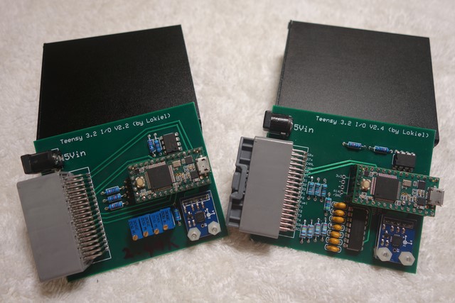
Image
Previous board on the left, new board on the right.

Now I need to master my 3D printer for the instrument cluster gauge.
I printed two small test models that turned out well but larger models aren't sticking to the bed and I have to terminate them very early.
Teething problems :(
Don't worry about dying, worry about not living!
Garage Thread: http://www.mx5cartalk.com/forum/viewtopic.php?f=57&t=76716


Return to “MX5 Garage Chat”

Who is online

Users browsing this forum: No registered users and 72 guests