DIY shift lights
Moderators: timk, Stu, -alex, miata, zombie, Andrew
-
Caffeine

- Racing Driver
- Posts: 1806
- Joined: Wed Apr 23, 2003 11:00 am
- Vehicle: NB8B
- Location: Sydney
Re: DIY shift lights
I made my own here. It works very well but I need to make up a new PCB with some extra circuitry. Planning on doing that in the next few weeks / months 
Supreme Blue NB8B, 1:16.98 at Wakefield when stock, but it's not stock any more...
-
Magpie
- Speed Racer
- Posts: 7468
- Joined: Fri Feb 11, 2011 12:49 pm
- Vehicle: NA6
- Location: Purga, QLD
Re: DIY shift lights
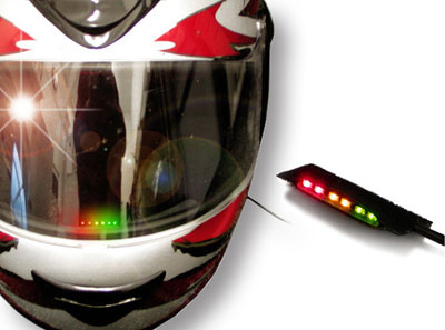
I was thinking about something like this, wired into the helmet for track days.
I have spare DPO's on the IO Expander that can be used for controlling a shift light, maybe a project for the new year.
I have spare DPO's on the IO Expander that can be used for controlling a shift light, maybe a project for the new year.
-
madjak
- Racing Driver
- Posts: 1117
- Joined: Tue Dec 31, 2013 12:11 pm
- Vehicle: NA6
Re: DIY shift lights
I'm using one of these https://www.autosportlabs.com/product/3-stage-sequential-shift-light/ wired up to the Haltech DPO's... I've just attached it in front of my dash and it's very visible.
The three stage works great. They are only set 300rpm apart but it helps me hit max revs just before the limiter kicks in. Mine are set at 7400, 7700 and 8000. I wait till I see the red lights turn on before shifting at around 8200.
Of course not so easy with a stock ECU... You need some sort of circuitry to take a pulsed input from the tach and convert it to revs and then some control to switch on the lights.
NA8: N/A 200whp | Haltech | Skunk2 Intake | S90 TB | RCP | 5 speed c/r dogbox | 4.78 diff | AST Shocks
Barbs L: 64.12 | S: 58.62 | Collie: 49.72
Barbs L: 64.12 | S: 58.62 | Collie: 49.72
-
hks_kansei

- Speed Racer
- Posts: 6154
- Joined: Tue Feb 03, 2009 10:43 am
- Vehicle: NB8A
- Location: Victoria
Re: DIY shift lights
madjak wrote:Of course not so easy with a stock ECU... You need some sort of circuitry to take a pulsed input from the tach and convert it to revs and then some control to switch on the lights.
Most of the aftermarket shift lights i've seen simply use voltage to know when to flash, you hold "set" at whatever RPM you want to have them activate, and it simply sets whatever the voltage is at that point as the trigger.
Not sure on the accuracy of them, I would assume taking the pulsed signal from the CAS or something would be a lot more accurate.
1999 Mazda MX5 - 1989 Honda CT110 (for sale) - 1994 Mazda 626 wagon (GF's)
-
Caffeine
- Racing Driver
- Posts: 1806
- Joined: Wed Apr 23, 2003 11:00 am
- Vehicle: NB8B
- Location: Sydney
Re: DIY shift lights
The NB tach signal is a PWM signal with constant duty cycle, so it will always read around 5v, regardless of rpm.
I used an AVR microcontroller to sample the tach signal and turn the LEDs on at the appropriate times. It's pretty basic hardware and trivial code.
I used an AVR microcontroller to sample the tach signal and turn the LEDs on at the appropriate times. It's pretty basic hardware and trivial code.
Supreme Blue NB8B, 1:16.98 at Wakefield when stock, but it's not stock any more...
-
Magpie
- Speed Racer
- Posts: 7468
- Joined: Fri Feb 11, 2011 12:49 pm
- Vehicle: NA6
- Location: Purga, QLD
Re: DIY shift lights
madjak thanks for the link, I think this will work 
You are using 3 DPO's then?
You are using 3 DPO's then?
-
madjak
- Racing Driver
- Posts: 1117
- Joined: Tue Dec 31, 2013 12:11 pm
- Vehicle: NA6
Re: DIY shift lights
Magpie wrote:madjak thanks for the link, I think this will work
You are using 3 DPO's then?
Yup... three DPOs. Very easy on a Haltech.
NA8: N/A 200whp | Haltech | Skunk2 Intake | S90 TB | RCP | 5 speed c/r dogbox | 4.78 diff | AST Shocks
Barbs L: 64.12 | S: 58.62 | Collie: 49.72
Barbs L: 64.12 | S: 58.62 | Collie: 49.72
-
madjak
- Racing Driver
- Posts: 1117
- Joined: Tue Dec 31, 2013 12:11 pm
- Vehicle: NA6
Re: DIY shift lights
Well if you're wanting to run shift lights then you are pushing the car close to the limit... which typically means you are also chasing power and so have an aftermarket ECU.
I run a shift light because I'm reving my engine to the max, and need to shift close to that limit without hitting it as that's where my power is. I ran without one for a while but I'm finding it's helping me keep my eyes on the track and not glancing at the tacho.
I run a shift light because I'm reving my engine to the max, and need to shift close to that limit without hitting it as that's where my power is. I ran without one for a while but I'm finding it's helping me keep my eyes on the track and not glancing at the tacho.
NA8: N/A 200whp | Haltech | Skunk2 Intake | S90 TB | RCP | 5 speed c/r dogbox | 4.78 diff | AST Shocks
Barbs L: 64.12 | S: 58.62 | Collie: 49.72
Barbs L: 64.12 | S: 58.62 | Collie: 49.72
-
Caffeine
- Racing Driver
- Posts: 1806
- Joined: Wed Apr 23, 2003 11:00 am
- Vehicle: NB8B
- Location: Sydney
Re: DIY shift lights
Stock ECU here. Shift light is just for fun.
Supreme Blue NB8B, 1:16.98 at Wakefield when stock, but it's not stock any more...
-
Magpie
- Speed Racer
- Posts: 7468
- Joined: Fri Feb 11, 2011 12:49 pm
- Vehicle: NA6
- Location: Purga, QLD
Re: DIY shift lights
madjak 
Mine is setup such that the lights start at 5,200 (start of good power) and flash to change at 8,000 (soft cut at 8,200). Therefore if on the track you always want to have at least 1 shift light on at all times however on the road you generally drive so as to not have a shift light come on.
Mine is setup such that the lights start at 5,200 (start of good power) and flash to change at 8,000 (soft cut at 8,200). Therefore if on the track you always want to have at least 1 shift light on at all times however on the road you generally drive so as to not have a shift light come on.
-
madjak
- Racing Driver
- Posts: 1117
- Joined: Tue Dec 31, 2013 12:11 pm
- Vehicle: NA6
Re: DIY shift lights
fair enough... something that would be very handy would be a controller like arduino that has a couple of analogue and digital inputs and then some simple logic to control some shift lights.
So something like:
Analog(1) = Coolant temp sensor
Analog(2) = Oil temp sensor
Digital(1) = Tach
If Analog(1) > 2.3volts turn on yellow lights
If Analog(2) > 2.6volts blink red lights
If digital(1) > 5000 rpm turn on green
If digital(1) > 6000 rpm turn on yellow
If digital(1) > 7000 rpm turn on red
(This is Furphy code btw... not actual code)
Magpie, I use the shift lights to get a countdown on shift... like 3-2-1-change. Because of they way my car is geared I'm only reving between 6000 and 8300 anyway with only a few seconds between gear changes. The lights go on real quick, like within a 0.5 second gap just like the launch lights at the drags and they just give me a lead in to the gear change.
NA8: N/A 200whp | Haltech | Skunk2 Intake | S90 TB | RCP | 5 speed c/r dogbox | 4.78 diff | AST Shocks
Barbs L: 64.12 | S: 58.62 | Collie: 49.72
Barbs L: 64.12 | S: 58.62 | Collie: 49.72
-
Caffeine
- Racing Driver
- Posts: 1806
- Joined: Wed Apr 23, 2003 11:00 am
- Vehicle: NB8B
- Location: Sydney
Re: DIY shift lights
The arduino is just an AVR microcontroller with some pre-built libraries. I use an ATTiny261
The code is pretty trivial (not very efficient, particularly with the 32 bit integers on an 8 bit micro, but quick and easy);
The code is pretty trivial (not very efficient, particularly with the 32 bit integers on an 8 bit micro, but quick and easy);
Code: Select all
/*
*
* Created: 12/02/2015 15:00:28
*  Author: liamo
*/
#define F_CPU 1000000    // AVR clock frequency in Hz, used by util/delay.h
#include <avr/io.h>
#include <util/delay.h>
#include <inttypes.h>
#include <avr/io.h>
#include <avr/interrupt.h>

#define SHIFT_POINT_1 5800
#define SHIFT_POINT_2 6000
#define SHIFT_POINT_3 6200
#define SHIFT_POINT_4 6400
#define SHIFT_POINT_5 6600
#define SHIFT_POINT_6 6800
#define SHIFT_POINT_7 7000
#define SHIFT_POINT_8 7200

#define LED1 PA0
#define LED2 PA1
#define LED3 PA2
#define LED4 PA3
#define LED5 PA4
#define LED6 PA5
#define LED7 PA6
#define LED8 PA7
#define LEDPORT PORTA
#define LEDDIR DDRA

#define HYSTERESIS 50

volatile int up = 0x01;
volatile uint32_t duration = 12000000;
volatile uint32_t RPM = 0x01;

void ioinit (void) /* Note [5] */
{
   LEDPORT = 0xFF; // All LEDs off
   LEDDIR = 0xFF; // All LEDs as outputs

   GIMSK |= _BV(INT0); // Enable INT0 interrupt
   MCUCR |=  _BV (ISC01);   // Setup for rising edge
   MCUCR |=  _BV (ISC00);

   // Setup Timer 1 with 1:1 prescaler = 1MHz (1 us per tick) since ckdiv8 fuse is enabled
   TCCR0B &= ~_BV(CS02);
   TCCR0B &= ~_BV(CS01);
   TCCR0B |= _BV(CS00);

   TCCR0A &= ~_BV(ICEN0); // Input capture mode off
   TCCR0A |= _BV(TCW0); // 16 bit mode

   TIMSK |= _BV(TOIE0); // Overflow interrupt enable

   // enable interrupts
   sei ();
}


void DoLeds()
{
   if(RPM >= SHIFT_POINT_1)
   {
      LEDPORT &= ~_BV(LED1);
   }
   if(RPM < SHIFT_POINT_1-HYSTERESIS)
   {
      LEDPORT |= _BV(LED1);
   }

   if(RPM >= SHIFT_POINT_2)
   {
      LEDPORT &= ~_BV(LED2);
   }
   if(RPM < SHIFT_POINT_2-HYSTERESIS)
   {
      LEDPORT |=_BV(LED2);
   }

   if(RPM >= SHIFT_POINT_3)
   {
      LEDPORT &= ~_BV(LED3);
   }
   if(RPM < SHIFT_POINT_3-HYSTERESIS)
   {
      LEDPORT |=_BV(LED3);
   }

   if(RPM >= SHIFT_POINT_4)
   {
      LEDPORT &= ~_BV(LED4);
   }
   if(RPM < SHIFT_POINT_4-HYSTERESIS)
   {
      LEDPORT |=_BV(LED4);
   }

   if(RPM >= SHIFT_POINT_5)
   {
      LEDPORT&= ~_BV(LED5);
   }
   if(RPM < SHIFT_POINT_5-HYSTERESIS)
   {
      LEDPORT |=_BV(LED5);
   }

   if(RPM >= SHIFT_POINT_6)
   {
      LEDPORT &= ~_BV(LED6);
   }
   if(RPM < SHIFT_POINT_6-HYSTERESIS)
   {
      LEDPORT |=_BV(LED6);
   }

   if(RPM >= SHIFT_POINT_7)
   {
      LEDPORT &= ~_BV(LED7);
   }
   if(RPM < SHIFT_POINT_7-HYSTERESIS)
   {
      LEDPORT |=_BV(LED7);
   }

   if(RPM >= SHIFT_POINT_8)
   {
      LEDPORT &= ~_BV(LED8);
   }
   if(RPM < SHIFT_POINT_8-HYSTERESIS)
   {
      LEDPORT|=_BV(LED8);
   }

}

int main(void)
{
   _delay_ms(500);

   ioinit ();

   int32_t RPMs[10];
   int index = 0;

   while(1)
   {
      RPMs[index++%10] = 12000000 / duration;;

      for (int i = 0; i< 10; i++)
      {
         RPM+= RPMs[i];
      }
      RPM/=10;

      DoLeds();
   }
}

SIGNAL (SIG_OVERFLOW0) //Timer has overflowed - takes 8ms
{
   duration = 12000000;
}

SIGNAL (SIG_INTERRUPT0) // edge detected
{
   if(up ==1) // Edge was rising
   {
      MCUCR |=  _BV (ISC01);   // Setup for falling edge
      MCUCR &=  ~_BV (ISC00);
      up = 0;
      TCNT0H = 0;
      TCNT0L = 0;
   }
   else
   {
      MCUCR |=  _BV (ISC01);   // Setup for rising edge
      MCUCR |=  _BV (ISC00);
      up = 1;

      duration = TCNT0L;
      duration |= ((uint32_t)TCNT0H << 8);
   }

}
Supreme Blue NB8B, 1:16.98 at Wakefield when stock, but it's not stock any more...
-
Caffeine
- Racing Driver
- Posts: 1806
- Joined: Wed Apr 23, 2003 11:00 am
- Vehicle: NB8B
- Location: Sydney
Re: DIY shift lights
Dundy2456 wrote:Ah ok, cool. Yeahthe code seems simple enough, there are a few people online who have got their examples up too and they all look pretty similar, functionality wise. I just grabbed an Arduino off the net today. I'm assuming there's a program to get the code onto the board?
There's an arduino IDE you can download which will compile and download the code for you
Supreme Blue NB8B, 1:16.98 at Wakefield when stock, but it's not stock any more...
-
Caffeine
- Racing Driver
- Posts: 1806
- Joined: Wed Apr 23, 2003 11:00 am
- Vehicle: NB8B
- Location: Sydney
Re: DIY shift lights
So I ended up getting some new PCBs made up with an appropriate circuit on them.

With woolies rewards card for scale by CaffeineAU, on Flickr
I've built one up, but don't have any photos of it yet. It's certainly much brighter than my first prototype
I also cleaned up the code a lot, got rid of the 32bit maths, and reduced code size from 1.7k to around 700 bytes. Not really necessary when I'm using a microcontroller with 8kbyte of memory, but it feels nicer
I'll have to install it, and then get a housing 3d printed for it.
Supreme Blue NB8B, 1:16.98 at Wakefield when stock, but it's not stock any more...
-
Caffeine
- Racing Driver
- Posts: 1806
- Joined: Wed Apr 23, 2003 11:00 am
- Vehicle: NB8B
- Location: Sydney
Re: DIY shift lights
Here it is, populated;

Populated Shiftlight by CaffeineAU, on Flickr
Just waiting on the arrival of some yellow LEDs. The orange ones I used are pretty much indistinguishable from the red ones. Also the part D1 is a diode that I underspecced (150mA continuous) and cooked, so a 1A replacement is also on its way.
I'd be interested in looking at the diagnostic port output for an NA, I think the code should be pretty similar, but I'd like to see if the hardware would still support it.
Supreme Blue NB8B, 1:16.98 at Wakefield when stock, but it's not stock any more...
Return to “MX5 Audio, Electronics & Lighting”
Who is online
Users browsing this forum: No registered users and 3 guests


