I Have been using strings on my own cars for a few years now (Chastity my NB8b, my parents Fiesta I use when I need more seats, my old Celica ST185 and my 62 Falcon. My friends 370Z and his girlfriend’s Fiesta). At the most recent Dodgy Day I did a full set up on JoshuaM’s NB8b this way and a few people wanted to know how. So I figured since I didn’t really get a chance to fully explain what I was doing and it would be better if it were written down.
First thing I would like to clarify; I won’t be going into set up specifications at all. When it comes to setting up a car you have to take into account wheel track difference, spring rates, damper rates, anti-roll bar stiffness, rake angle, roll center heights, the speed you want it to be dríven at, the weight distribution, the drivers weight (and passenger if applicable), available tyre grip, the diff ratio and center type (IE; T1 or T2 or open or what-ever you have will change the behaviour) then on top of all of this there is your personal preference as to how the car reacts to inputs and just what style of car you like to drive. Over the last year, I've taken all of the above into account and slowly massaged my car into MY perfect handling MX5. Anyone else could get in it with a different driving style and not like it. So the purpose of this is just how I measure and adjust the camber caster or toe.
Secondly, this is not necessarily a superior alternative to getting a race shop to laser align the car. But most shops from my experience won’t take the time to make sure it’s perfect as it is (very) time consuming.
Caster
First thing I like to adjust is front caster. On the first and second gen MX5s, this is changed on the rearward adjustment bolt on the front lower control arm. Adjust this as you would any of the other alignment adjusting bolts, undo the locknut and move the bolt to the desired point then redo the nut. (See the shop manual for torque setting)
It is important to have the control arm at its loaded position when doing up the lock nut. With the car on stands you can use a jack to lift the control arm as required then tighten it off. Be very careful that the bolt doesn't turn as this will change the caster setting. (Also important to note, that changing the caster will also change the wheel base, both the effective and actual.)
How to Measure Caster
The caster setting is a positive angle when the vertical line the wheel turns about leans toward the back of the car, putting the line of rotation as you turn the steering wheel in front of the tyres contact patch with the road. This is for stability and steering feel and so on, but more importantly sets how the camber of the wheel changes when you turn the steering wheel. More caster = more camber change as you turn the wheel. The reference point for measuring this number is when the wheels are turned 20° each way.
So you have to work out where exactly 20° at the wheel is from center. (See measuring toe) mark the steering wheel in a way that makes sense to you, so you can put it back to that position as much as you need.
Start by turning the wheels so they are 20° to the right and measure the camber. Then turn them 20° to the left and measure the camber again. The difference between the two camber angles is your caster setting. (See measuring camber).
Camber
Measuring
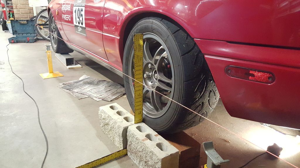
There are a couple of ways of measuring camber. My car has stock wheels so they sit about an inch inside the arches. So I can use a string with weights at each end, that when draped over the front or back of the car along the axle line, don’t quite touch the floor. This allows the hanging strings to act as a plumb line, providing a vertical reference line to measure from. Then measure the distance from the string to the top and bottom edges of the rim.
A negative camber setting will have a larger measurement at the top than the bottom. Using these two measurements and some trigonometry the camber value can be found. This is calculated as follows;
On my 16" rims, the difference between the top and bottom of the rim where I measure is 440mm. This is your hypotenuse of the right angle triangle between the string and wheel.
Sin(ϴ) = (Opposite/Hypotenuse)
ϴ = camber angle.
Opposite = (top distance measurement) - (bottom distance measurement)
So say I want 1.6° of camber on my 16" rim. What is the measurement difference I need?
440sin(1.6) = 12.3mm
The difference between the top and bottom measurements should be 12.3mm. You can go the other was as well using the inverse of sin to work out how much camber you have. Also if you're interpreting shop print out 1.6° converts to 1°36' (Because they often print out in DMS units. ((1degree plus (0.6x60)minutes))
I found with cars with wider wheel offsets the string method doesn't work as the bottom of the wheel pokes out past the body work. So you can do exactly the same but with a laser level plumb as the vertical reference line instead of the string.
Another way is to use a digital level and straight edge against the wheel and it will just tell you the angle.
Adjusting
On the front wheels it is the forward bolt on the lower control arm, pushing the bottom of the wheel outwards with this bolt increases negative camber, pulling it in reduces camber. Same as with tightening off all these bolts, with car on stands use a jack to hold the control arm up and tighten the lock nut. Again be very careful that the bolt itself doesn't turn as that will mess up your adjustment.
For the rear camber. Only the lower control arms are adjustable. Turning both bolts an equal amount changes the camber. Adjusting one separate of each other changes the toe and the camber at the same time. This isn't a big issue if you run a straight toe, as you can adjust both the same and then trim the toe a tiny bit. If for your preferences you like non straight toes, for the back it is probably easier to set the rear toe first then adjust the camber. (Bear in mind you will have to redo the toe afterwards as it will change a tiny bit again.)
Adjust and tighten these bolts with the same method as described for front camber and caster. Same method for measuring camber at the back as mentioned before for the front.
Toe
Measuring
Now onto measuring toe, this is very fiddly. A lot of care and patience is required.
Before you start you need to know the wheel tracks (more importantly the difference between front and rear tracks)
On my NB8b the rear track is 25mm wider than the front track. Divide this by 2 is 12.5mm narrower at the front on each side.
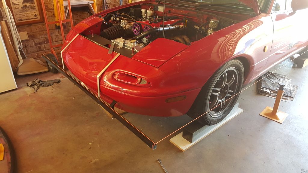
The Aim here is to get a string line perfectly parallel to the side of the car. I like to use some fluorescent brickies string taught between two jack stands. The string should be at the height of the wheel centers.
I then get two more pieces of string and tie each one around the diameter of each wheel. Once tied tight around the wheel, this makes it much easier to measure where the center of the wheel is relative to the parallel string.
Now to set the string parallel to the car.
Drive the car into the garage with the steering wheel in the perfectly straight ahead position. Regardless if the alignment isn't straight yet. Drive in gently and stop as smoothly as possible. This ensures that the tyres and bushings are loaded as they would be whilst driving straight ahead ensuring the most accurate reading.
Once the car is parked with steering wheel straight, tie the strings around the wheels so they are along the diameter. (Crossing over the center cap as this will be the reference point for the axle width.) Now align the string that's between the two jack stands so it is (in my case) 100mm away from the center point of the string on the rear wheel, and 112.5mm from the center point of the string on the front wheel. Yes the half a millimeter matters. So take your time getting this perfect.
The following images demonstrate how I have the strings set up for measuring toe.


At this stage I want to clarify something. Measuring from the center point of the wheels to find parallel to the car is just as accurate as the laser systems. If not more so. The laser wheel attachment sits a fair distance out from the wheel so as the toe changes the track width at that wheel will change very slightly, causing the parallel line to become a different measurement. When measuring with the string on the wheel on a standard offset this change is very small. (Small angle theorem would negate it) and because you are much closer to the wheel than a laser system it becomes more accurate.
Once you are happy that the string is perfectly parallel to the car, you can now measure the toe amounts.
Measure the distance from the parallel string to the front of the wheel (make sure your measuring implement is level) record this value. Then measure the distance from the parallel string to the back of the rim, record this value. The difference between the two is the toe, in millimeters for that wheel. Repeat for every wheel. From here you can adjust them to what you want them to be.
If you want to know what the toe is in degrees. You can use exactly the same maths as demonstrated for calculating the camber.
Adjusting Toe
Adjusting the Toe for the front is a relatively simple procedure. On the tie rod there is a 17mm lock nut, undo that and wind it out of the way. Now to adjust the toe, using a 12mm spanner turn the tie rod relative to the tie rod end. Pulling the tie rod in toward the car increases toe in, and pushing it out increases toe out. (Bear in mind one side has a reverse thread.) Once adjusted the required amount, do the locknut back up. Be careful when doing this nut back up, as when it grabs onto the tie rod end, it tends to turn the tie rod end relative to the thread. This can be overcome by turning both the lock nut and tie rod equally until the tie rod ends stops turning relative to the tie rod. Then tighten off the lock nut.
The back is done by adjusting one of the lower control arm adjusting bolts at a time (or relative to each other).
For reference one full turn of the tie rod on the front is a change of 3.5mm (0.46° or 0°27’) of toe (measured on a stock 16" rim) and approximately 5° of rotation on one of the rear toe/camber bolts changes the rear toe by 1mm(0.13° or 0°7’49”) (again, measured on a stock offset 16" rim).
Things to note
So some other things to do to make sure it’s as accurate as possible. The area where you do this has to be as level as physically possible. Especially for setting the camber.
Also because I'm a perfectionist, whilst taking all measurements, I have 3 bags of cement render in the driver’s seat simulating my weight to ensure the corner weighting is as accurate as possible. (Again, especially important when setting camber.)
After every single adjustment, reverse the car a couple of car lengths, and then drive perfectly straight back in. Again ensuring the steering wheel is centered. Then remeasure to see if the settings you desired were attained. This is where most of the problems come up with getting tyres shops and the like to laser align the car. The changes cause small amounts of binding in the system, that unless it is released will cause a correct reading on the computer read out to go awry as soon as you drive away from the shop.
It takes a while to get the hang of and when you do a lot of different cars you have to learn which adjustments change what for different suspension systems.